

Page 1

IMPORTANT
www.universal-space.com
Operation Manual
Page 2

Lane Master Pro GMP Manual
WE ARE HERE TO ASSIST
For parts and service
Have Questions? Contact us!
UNIS SERVICE CENTER
Tel: 972-241-4263
Fax: 214-919-4918
Email: [email protected]
07/12/2018
1
Page 3

Lane Master Pro GMP Manual
CONTENT
IMPORTANT SAFETY INSTRUCTIONS ........................................................................ 3
1. SPECIFICATIONS ..................................................................................................... 5
2. CONTENTS OF THE ACCESSORY KIT .................................................................... 7
3. PART NAME .............................................................................................................. 8
4. SET UP & INSTALLATION ........................................................................................ 9
5. HOW TO PLAY ........................................................................................................ 12
6. GAME OPTION ....................................................................................................... 13
7. TROUBLE SHOOTINGS .......................................................................................... 19
8. MAINTENANCE & INSPECTION ........................................................................... 22
9. OVERALL CONSTRUCTION ................................................................................... 24
10. WIRING DIAGRAM .............................................................................................. 34
2
07/12/2018
Page 4

Lane Master Pro GMP Manual
Thank you for purchasing Lane Master Pro. We hope you enjoy the product.
This manual contains valuable information about how to operate and maintain your game
machine properly and safely. It is intended for the owner and/or personnel in charge of
product operation. Carefully read and understand the instructions.
If you need any help during installation and setup please utilize this manual and
troubleshooting guide. If the product fails to function properly, non-technical personnel
should under no circumstance attempt to service the machine. Contact your distributor or
manufacturer for help.
Before use, please read IMPORTANT SAFETY INSTRUCTIONS.
IMPORTANT SAFETY INSTRUCTIONS
To ensure the safe usage of this product, carefully read and
understand these instructions before operating your game.
Save these instructions for future reference.
Use this product only as described in this manual. Other uses not recommended may
cause fire, electric shock or personal injury. Unplug the game from the outlet when not in
use, when moving from one location to another, and before cleaning/servicing.
Explanations which require special attention are indicated by signs of warning. Depending
on the potential hazardous degree, the terms: NOTE, NOTICE, and WARNING are used.
NOTE: A NOTE indicates useful hints or information about product usage.
NOTICE: A NOTICE indicates potential damage to product and how to avoid the problem.
WARNING: A WARNING indicates a potential for product damage or serious personal Injury.
It is important to understand the meaning of the following HAZARD SIGNS before
continuing:
High Voltage and Shock Hazard:
High voltage can cause electric shock.
Turn off/unplug power before servicing.
High Temperature Hazard:
This part may cause scalding.
Do not touch. Surface may be hot.
No Touching Hazard:
This part may be hot or can cause electric shock.
Do not touch.
07/12/2018
3
Page 5

Lane Master Pro GMP Manual
Use the following safety guidelines to help ensure your own personal safety and to help
protect your equipment and surrounding environment from potential damage.
This product is an indoor game machine. Do not install outdoors.
Avoid installing in the following places to prevent fire, electric shock, injury
and/or machine malfunctioning:
Places subject to rain/moisture, or places subject to high humidity.
Places subject to direct sunlight, or places subject to extremely hot or cold
temperatures to ensure that it is used within the specified operating range.
Places where inflammable gas may be present or in the vicinity of highly
inflammable/volatile chemicals or items that can easily catch fire.
On unstable or sloped surfaces. The machine may topple or cause unforeseen
accidents.
Vicinity of fire exits, fire extinguishers etc that may block/prevent safety measures.
IMPORTANT NOTE:
ALL REPAIRS MUST BE DONE TO ORIGINAL MANUFACTURER SPECIFICATIONS.
FAILURE TO DO SO VOID ALL WARRANTIES AND OPERATOR ASSUMES ALL
RISKS.
Note: The contents of this manual may be updated without notice.
4
07/12/2018
Page 6

1. SPECIFICATIONS
Rated power supply: AC110V 50/60Hz; AC220V 50/60Hz;
Min. Power consumption: 250W
Max. Power consumption: 300W
Dimension: W26.4×D96.6×H101.2 in
W 670×D2452.5 ×H2568.8 mm
Weight:Approximately 474 lb
Approximately 215 kg
Part No: L114
Model No: C-525
Lane Master Pro GMP Manual
NOTICE: After turning off the game, please wait at least 1 minute
before restarting again.
Note: Game specifications are subject to change without notice.
07/12/2018
5
Page 7

Lane Master Pro GMP Manual
This machine will be divided into two parts during transportation.
Back Cabinet: W26.4×D24.2×H82.3 in
W670×D615×H2089 mm
Ally part: W26.4×D72.4×H25.9 in
W670×D1837.5×H658 mm
Note: Game specifications are subject to change without notice.
6
07/12/2018
Page 8

Lane Master Pro GMP Manual
2. CONTENTS OF THE ACCESSORY KIT
Open the package and make sure all the items are included:
1. Following accessories
For 110V
No. Part No. Code Name Picture Qty
1 L114-170-000 20611605027A
Bowling ball
2
2 L114-747-000 40607000012
3 L114-801-000 25300171002
4 L114-802-000 25300172002
5 L114-430-000 23301010020
Wrench 2
key
key
Power cord
1
1
2
6 L114-803-000 41440000173F
7 L114-412-000 21901000013
8 L114-433-00 21107120003
Manual
Fuse
Wireless
keyboard&mouse
1
2
1
For 220V
No. Part No. Code Name Picture Qty
1 L114-411-000 21901000012
Fuse
2
NOTE: Part models are subject to change without notice.
07/12/2018
7
Page 9

Lane Master Pro GMP Manual
3. PART NAME
Key Components
Marquee Assy.
27” Monitor
42” Monitor
Lane
Printer
Ball exit
8
07/12/2018
Page 10

4. SET UP & INSTALLATION
Lane Master Pro GMP Manual
We do not recommend using power tools as they may cause damage.
This product is an indoor game machine. Do not install outdoors.
Refer to IMPORTANT SAFETY INSTRUCTIONS (Pg. 3) for places to avoid
Place the unit on a dry level surface
Ventilation openings in the back of the unit must not be obstructed by objects or by
wall.
4.1 Transporting the Game
NOTICE
If you need to move the game, adjust the levelers back to an “up” position.
Leveler Caster
Move
NOTICE
Be careful not to damage the machine during transport.
Always unplug the game before moving.
Keep the machine in upright position during transport.
For longer distance transport, package the game properly to prevent damages.
4.2 Level Adjustment
Install this machine on a flat surface. Adjust levers to lift casters off the ground to level the
.
game
To secure the game, adjust the Leveler down until it touches the floor, lifting the casters off
the ground by 0.2 in. Repeat the same for all levelers.
If the game is installed on an unsuitable floor, it could cause game malfunction.
Leveler
Caster
About
0.2 in
Move
Make sure the machine is level.
NOTICE
Fix
9
07/12/2018
Page 11

Lane Master Pro GMP Manual
4.3 Play Zone
This machine requires space for playing and for maintenance as shown below.
Leave space around the game upon installation:
Service area: 20 in
Service area
10
07/12/2018
Play area
NOTICE
Your unit must be leveled to operate properly.
Page 12

Lane Master Pro GMP Manual
4.4 Machine Installation
4.4.1 Marquee Installation
Before processing with assembly assure you have the following tool.
Step 1 Upright the marquee and use Allen hexagon wrench to install two screws as picture
shown.
No.
Name
1
Allen hexagon wrench
Please install the screws as red arrow shown
Picture
07/12/2018
11
Page 13

Lane Master Pro GMP Manual
4.4.2
Step 1 Use the Allen hexagon wrench (Provided) to lock the back box with the lanes as
indicated.
Step 2 Lower leg levelers into place for initial leveling of the back box and the lanes if the
floor is uneven.
Step 3 Add ball to each lane and apply power.
Step 4 Once game is powered on and operational place it in position. Utilizing the leg
levelers to assure the back box and lanes are level with each other.
Connect Lane Assembly & Display Assembly
Lock Unlock
12
07/12/2018
Page 14
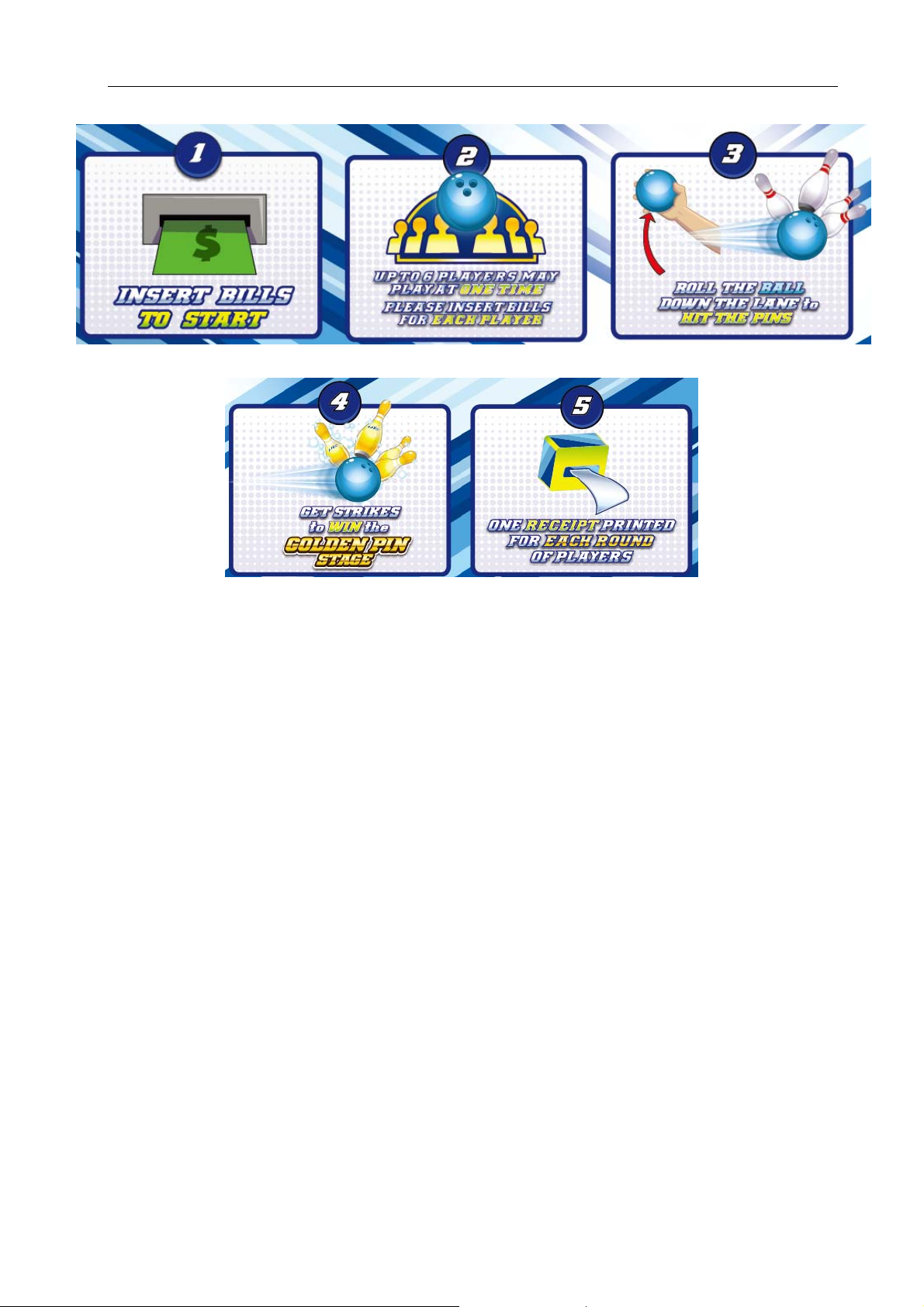
5. HOW TO PLAY
Lane Master Pro GMP Manual
07/12/2018
13
Page 15
Lane Master Pro GMP Manual
6. GAME OPTION
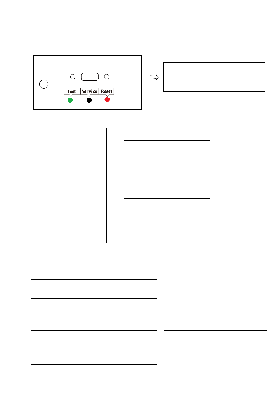
6.1 Adjustment button instruction
6.2 Setting menu
6.2.1 Main menu
Basic Setting
Customized Setting
Coupon content setting
Input Test
Output Test
Game Reset
Date/Time Setting
Language/语言
About This Game
Bookkeeping
6.2.2 Basic Setting
Open the coin door and there is a
meter panel. Press Settings button to
enter into the setting menu.
Free Play OFF/ON (OFF)
Demo Music OFF/ON (ON)
Memory Save OFF/ON (ON)
Volume 1-10 (7)
Coins Per Game 1-10 (1)
Pay Mode Insert bills
Go Back&Save
Back
DailyRecord
Back to game
6.2.3 Customized Setting
Coupon input option Prize input/Score input
Regulation Mode OFF/ON(ON)
Alternating Ball Color OFF/ON(ON)
Number of Frames Frame 1-10(3)
Multiplayer Join Time 5-60(20)
Number Of Strike(s)
To Activate Golden Pin
Stage
Golden Pin Stage OFF/ON(ON)
Golden Pins Set 10-100(100)
Each Golden Pin
Score
Bumper Version OFF/ON(ON)
14
07/12/2018
1-3(1)
1-10(ON)
Strike Zone
Game Level
No Ball Found OFF/ON (ON)
Type In Player
Name After
Top Ranking OFF/ON(ON)
Type In Name
Time
Number of
Top Players
Minimum
Score to show
on Ranking
Go Back & Save
Back
Easy/Normal/Difficult
(Normal)
Credit In/ Game Over
(Game Over)
5-60(20)
5-20(20)
100-200-500-600-8001000-1200-1500-2000
(100)
Page 16
Lane Master Pro GMP Manual
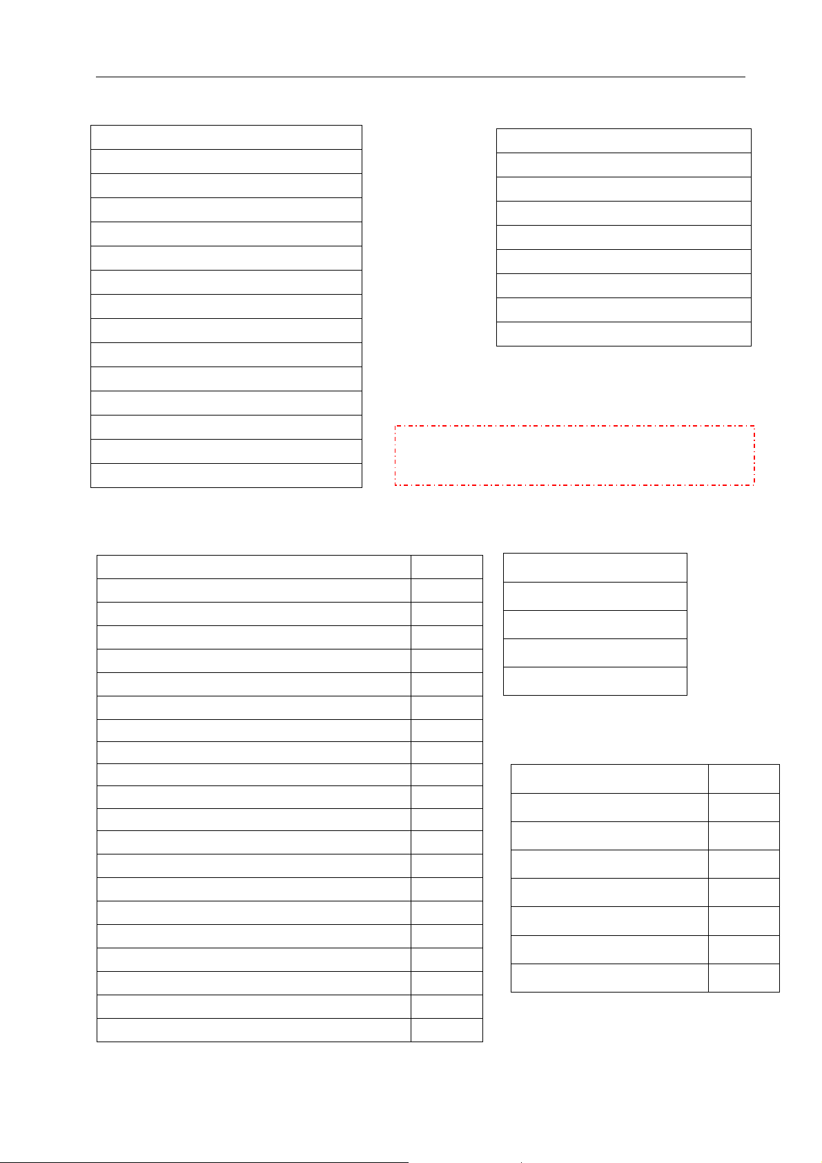
6.2.4 Coupon content setting
Prize Input: Score Input:
Shop name
(Enter the shop name)
Prize content
1 ST (enter prize name)
2 ND (enter prize name)
3 RD (enter prize name)
4 TH (enter prize name)
5 TH (enter prize name)
6 TH (enter prize name)
(Enable to enter 1000 characters)
Shop Name
(Enter the shop name)
Comments
Save
Clear All
Test
Exit
Comments
(Enable to enter 256 characters)
Save
Clear All
Note: Before processing this setting, please set
Test
the Coupon Input Option first.
Exit
6.2.5Input Test 6.2.6 Output Test
Enter Button OFF/ON
Left Button OFF/ON
Right Button OFF/ON
Enter Button Light
Left Button Light
Right Button Light
Coin OFF/ON
Send Ball Sensor Initial Position OFF/ON
Ball Detect OFF/ON
Ball Signal
OFF/ON
Ball Release Test
Back
Ball Location 0-100
Ball Speed 0-100
Ball Direction 0-180
Detection Time for Ball to Pass Sensor1 0
6.2.7 Game Reset
Factory Restore YES/NO
Reset Basic Setting YES/NO
Detection Time for Ball to Pass Sensor2 0
Detection Time for Ball to Pass Sensor3 0
Detection Time for Ball to Pass Sensor4 0
Detection Time for Ball to Pass Sensor5 0
Infrared1 OFF/ON
Reset Customized Setting YES/NO
Clear All Records YES/NO
Clear Owed Ticket YES/NO
Clear Unused Coin YES/NO
Infrared2 OFF/ON
Infrared3 OFF/ON
Infrared4 OFF/ON
Infrared5 OFF/ON
Reset Top Ranking Score YES/NO
Back
Send Ball Error OFF/ON
07/12/2018
15
Page 17
Lane Master Pro GMP Manual
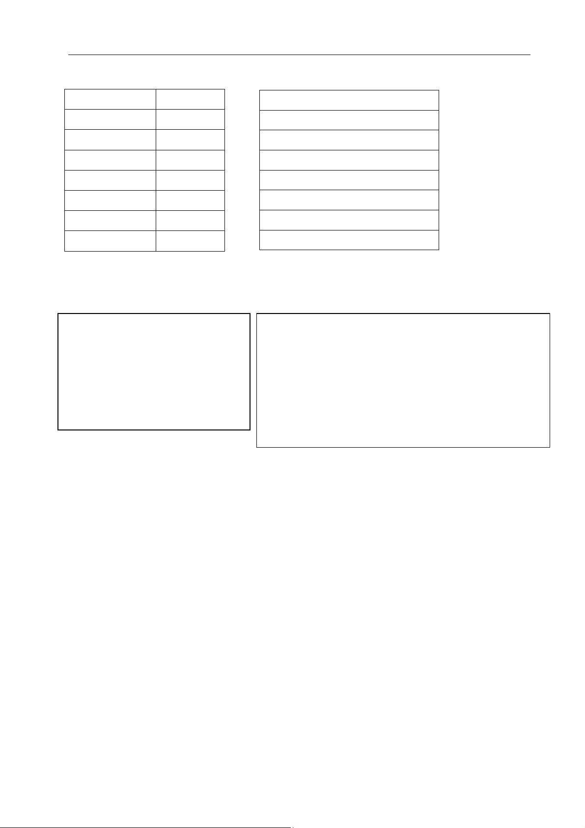
6.2.8 Date/Time Setting 6.2.9 About This Game
Year 2010-2100
Month 1-12
Day 1-31
Hour(24) 0-23
Minute 0-59
Second 0-59
Go Back & Save
Back
6.2.10 Bookkeeping
Player1 Bills
1 0
These Settings Are Non-Resettable
Back
Press the Test Button to Go Back
CPU
Motherboard
Disk Drive
Memory
Display Adapter
Monitor
Screen
6.2.11 Daily Record
Date Weekday RunTime Bills
2014-06-06 Fri 00:00 0
Clear
Back
16
07/12/2018
Page 18
Lane Master Pro GMP Manual
1
6.3 Display Advertisement Operation
In Version 1.05 or higher version for Lane Master, operator can put advertisement to the
machine and display on the top monitor.
Please note that the advertisement video format has to be AVI.
Please prepare a mouse, a keyboard and a memory stick.
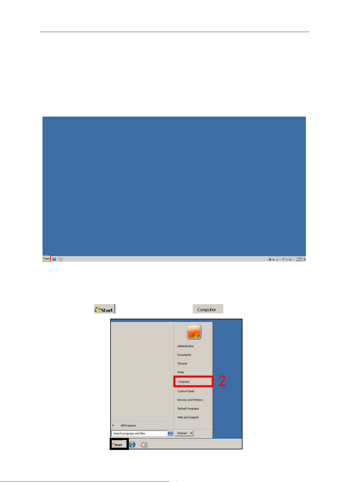
Step 1
Power down the machine. Plug in a mouse and a keyboard. Power up the machine. Insert a
memory stick after the pc shows system interface.
Note: Please do not put any ghost system file to the memory stick and do not insert the
memory stick before powering up the machine. This may cause damage to the system.
Step 2
1&2.Click “Start”
1
and choose ”Computer”
07/12/2018
17
Page 19
Lane Master Pro GMP Manual
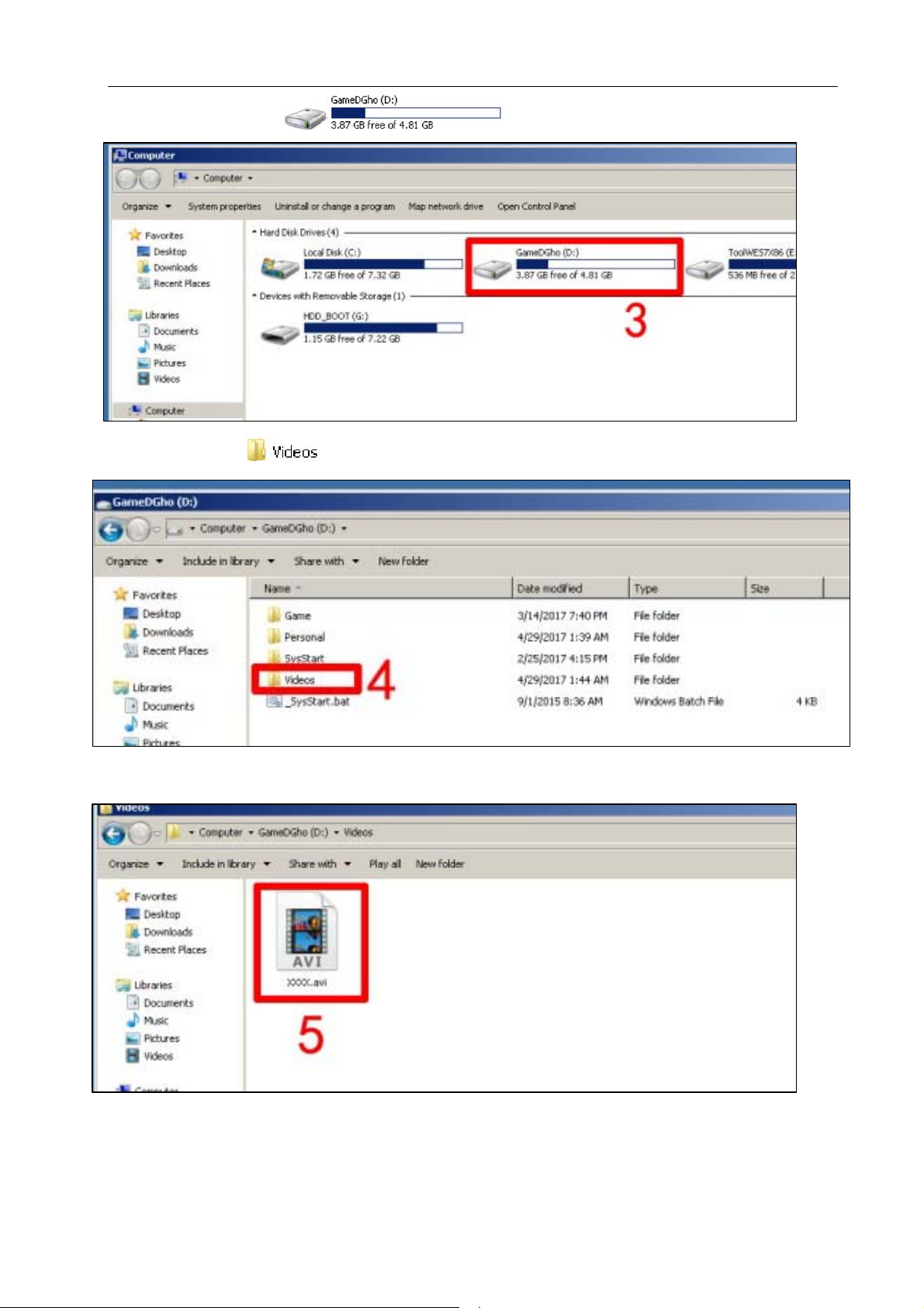
3.Click” GameDGho”
4.Click ”Videos”
5.Copy the AVI file from memory stick into “Videos” folder.
Step 3
Unplug the memory stick. Power off and restart the machine. The advertisement video will
be shown on the top screen. If the video format is not AVI. It will show an error as below.
18
07/12/2018
Page 20
Lane Master Pro GMP Manual
7. TROUBLESHOOTING
7.1 Common Problem
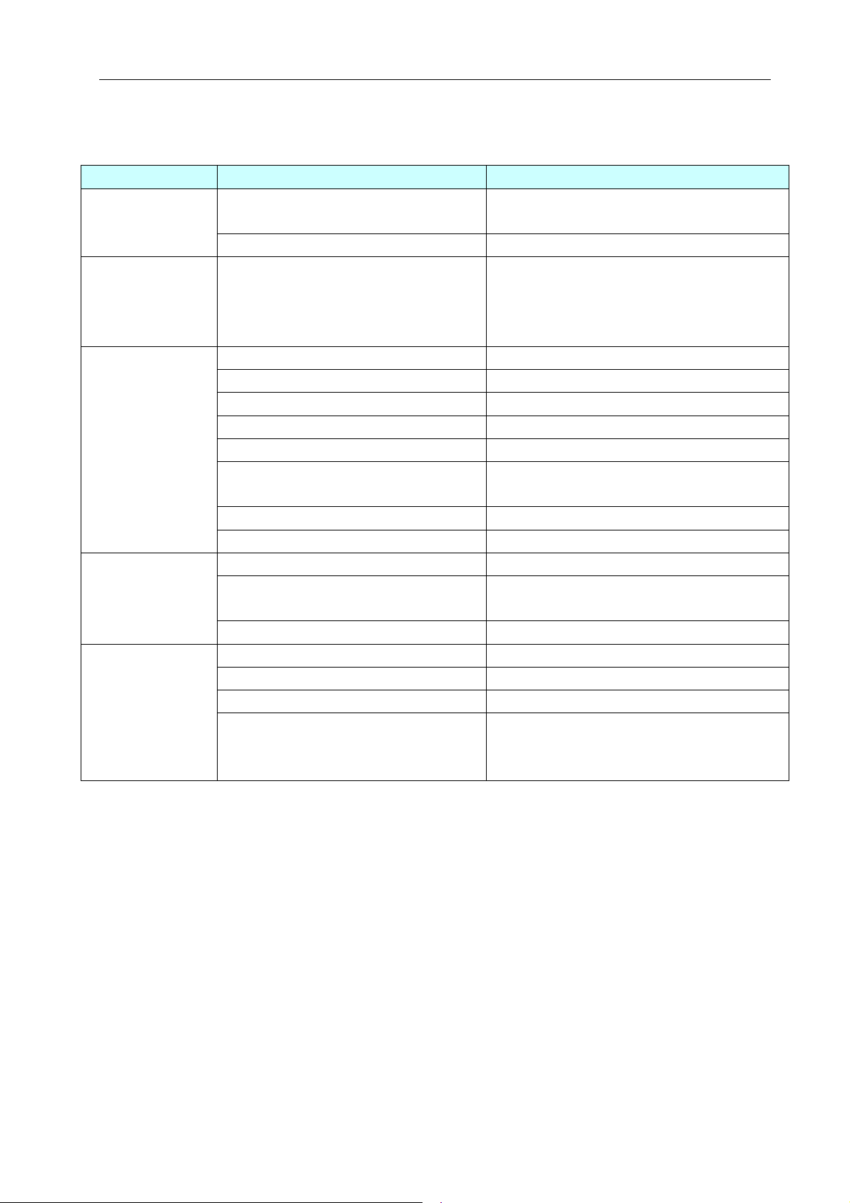
Please confirm that all connectors fit tightly.
Symptom Possible Cause Recommended action
Game will not
start
Power off
No sound
Display black
screen
Display blue
screen
Frame assembly connector is
loose.
Frame assembly fault Contact with UNIS Service.
Turn on power SW again. If appeared
Circuit protector make power SW
in off state.
Low volume Raise the volume.
Connector loose. Check connector.
Speaker fault. Check speaker.
POT installation error. Install POT correctly.
POT fault. Change POT.
Audio cable problem.
PC crash. Restart or system recovery.
Driver problem Restart the audio driver.
Check connectors. Plug in connector tightly
Display fault.
RAM is loose. Remove and reinsert RAM.
PC power cord is loose Check PC power cord whether is loose.
VGA signal cable is loose. Check VGA cable
PC video card is loose. Reseat video card.
“0X000000A” code appears.
Conflict between computer drive
and software.
again and again, machine has
anomaly. Please contact with UNIS
Reconnect the audio cable or change
Utilize another source such as a PC to
verity if the display is operational.
Check connector.
Service.
it.
Contact service
Note: After replacing component from pc (except for RAM), and replacing monitor, the
game should be recovered again with the memory stick attached to the machine.
07/12/2018
19
Page 21
Lane Master Pro GMP Manual
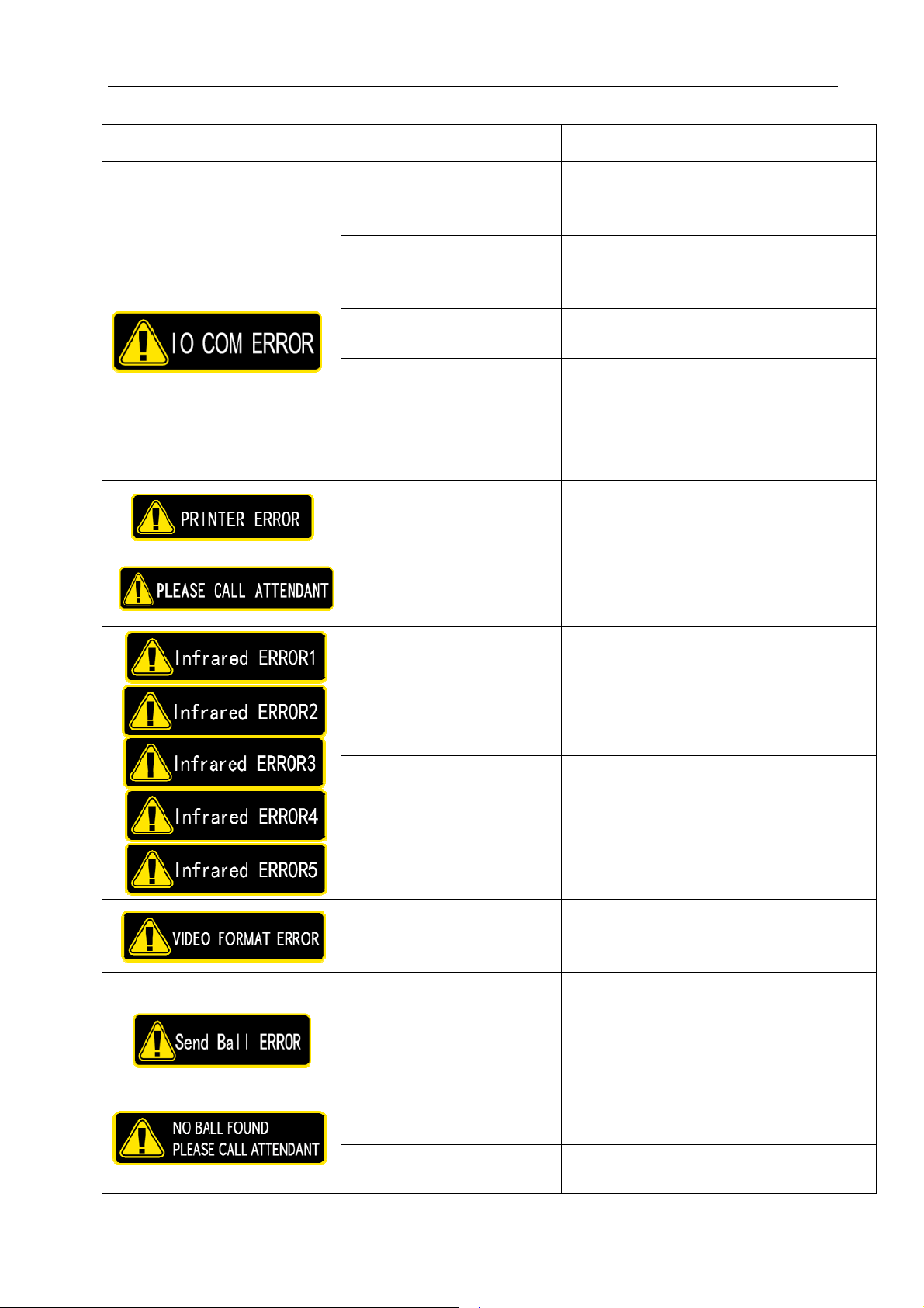
If you see following error signs showing on the display, please try the recommended action.
Display Possible Cause Recommended action
The connection part of
the IO board and PC are
loose.
USB cable quality
problem
USB cable became loose
during transportation.
Check and reconnect the loose ports
of the PC or IO board.
Change the USB cable after checking
the connection between IO board and
PC.
Check and reconnect the loose
cables of the PC or IO board.
Reboot the game after checking USB
connection and USB cable problem,
IO board is faulty.
if the problem remains unresolved,
please call the service department
for assistance.
Printer error.
Out of paper.
Check and reconnect the loose
cables of printer.
Add paper.
Out of ticket. Refill tickets and press reset button.
Loose connection to the
sensor’s cables.
Check and reconnect the loose
cables of sensor.
Sensor problem.
Wrong format for the
video.
Change the sensor after checking the
connection.
Please note that the advertisement
video format has to be AVI.
Loose connection of the
send ball assembly.
Send ball assembly is
broken.
No ball found inside the
lane.
Sensor problem.
Check and reconnect the loose
cables of send ball assembly.
Check the connection, if the problem
remains unresolved, please call the
service department for assistance.
Roll a ball to the lane.
Change the sensor after checking the
connection.
20
07/12/2018
Page 22
Lane Master Pro GMP Manual
7.2 System Recovery Operation
(NOTE: Do not disconnect power during this process.)
1. Turn off the game. Remove recovery USB from the machine. (Note: This process may
take up to 60 minutes) Insert the memory stick into the USB port at the back of the
computer.
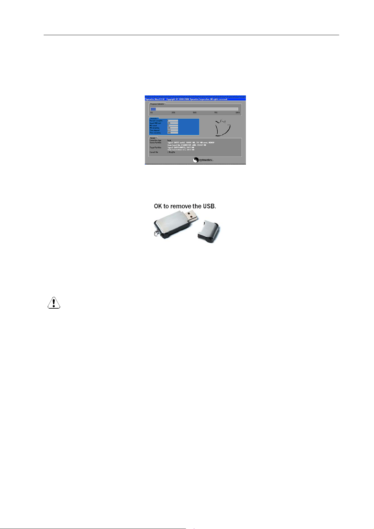
2. Restart PC to enter the system recovery screen as shown.
3. The game will automatically start recovery.
4. Once system recovery is partially finished (as shown below), and the ICON appears,
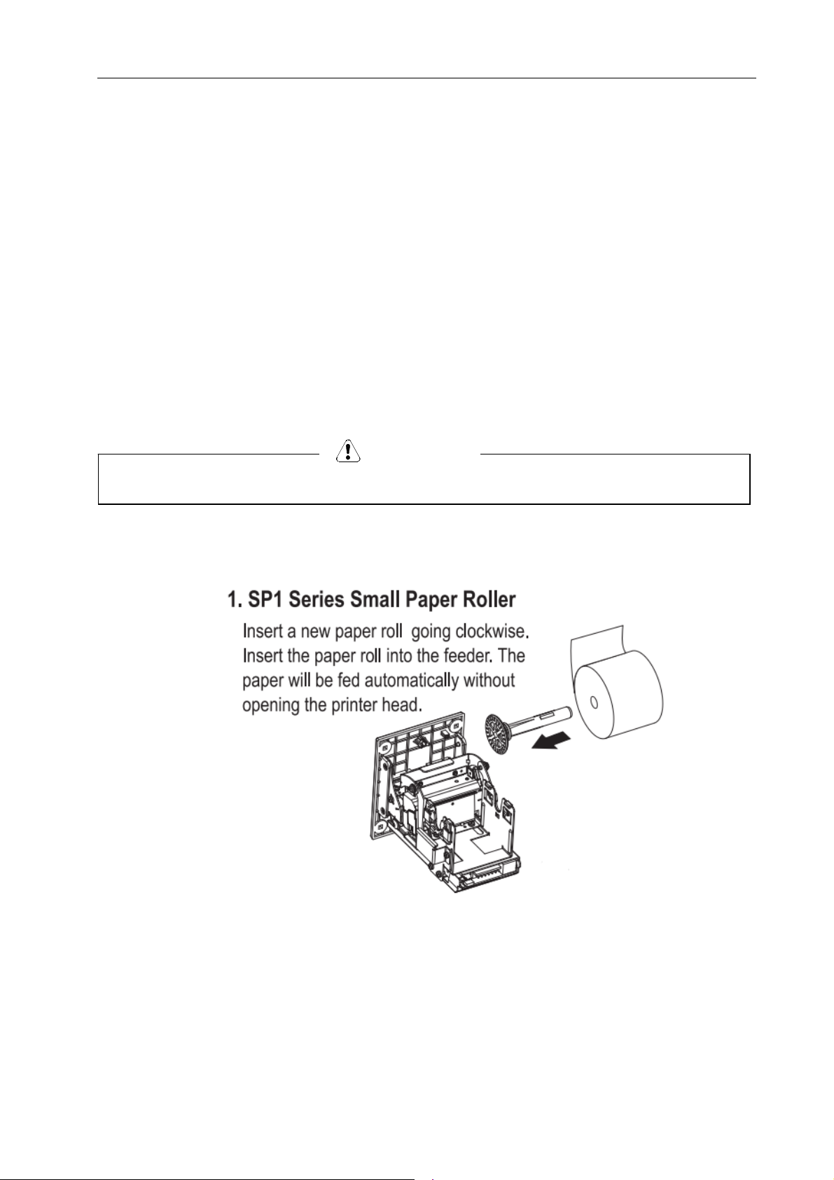
remove the USB flash drive from the computer. The game will continue the install process.
5. Assure that the recovery USB has been properly secured for future use.
WARNING: the USB flash drive should only be used to fix software errors. Using it for
other purposes may cause unexpected results and damages.
07/12/2018
21
Page 23
Lane Master Pro GMP Manual
8. MAINTENANCE & INSPECTION
8.1 Safety Check
Check the points listed before operating the machine. These checks are necessary for safe
machine operation:
1. Test game before operation each day.
2. Conduct monthly routine checks of game components to ensure good working
condition
3. Check the machine regularly for dust and clean when necessary.
Note: Parts and components require preventative maintenance to maintain proper
operation.
8.2 Handling Precautions
When installing or inspecting the machine, be very careful of the following points and
pay attention to ensure that the player can enjoy the game safely.
Non-compliance with the following points or inappropriate handling running counter to the
cautionary matters herein stated can cause personal injury or damage to the machine.
We do not recommend using power tools as they may cause damage.
NOTICE
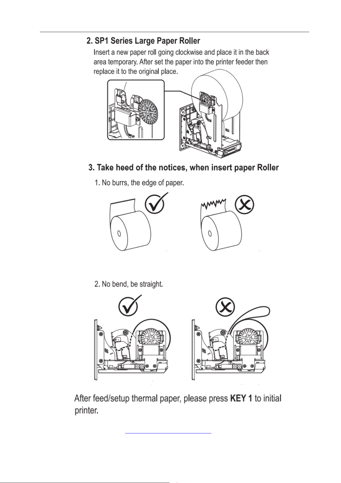
8.3 How to replace the paper roll of the printer?
Open the front door and follow the steps.
22
07/12/2018
Page 24
Lane Master Pro GMP Manual
Note: Please visit http://www.ictgroup.com.tw/
for more information.
07/12/2018
23
Page 25
Lane Master Pro GMP Manual
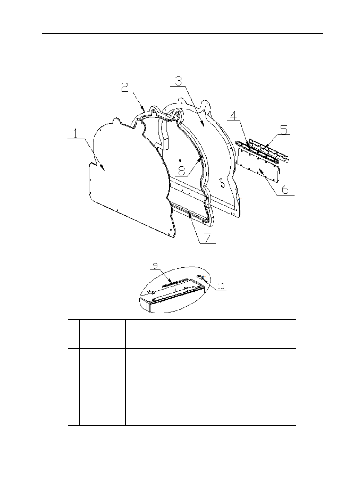
9. OVERALL CONSTRUCTION
9.1 Marquee assy.
24
07/12/2018
No. Part No. Code No. Name Qty
1 L114-713-000 20511605E003
2 L114-166-000 20611605E008
3 L114-164-000 20211605E028
4 L114-169-000 20211605E030
5 L114-144-000 20211605E031
6 L114-168-000 20211605E029
7 L114-165-000 20611605E007
8 L114-167-000 20611605E009
9 L114-169-000 20211605E030
10 L114-138-000 20211605E016
Marquee decal 1
Marquee plastic 2 1
Marquee shell 1
Hinge fix bracket 1
Hinge 2
Hinge connect plate 1
Marquee plastic 1 1
Marquee plastic 3 1
Hinge fix bracket 1
Marquee fix bracket 2
Page 26
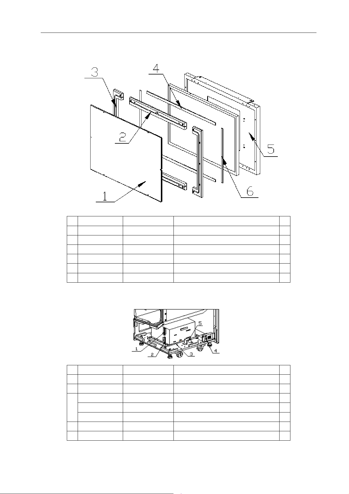
9.2 Top monitor assy.
Lane Master Pro GMP Manual
No. Part No. Code No. Name Qty
1 L114-701-000 20511605E001
2 L114-123-000 20611605E002
3 L114-122-000 20611605E001
4 L114-124-000 20611605E012
5 L114-121-000 20211605E012
6 L114-125-000 20611605E013
9.3 PC assy.
No. Part No. Code No. Name Qty
1 L114-182-000 26000064000
2 L114-180-000 26000055000
L114-178-000 26000012000
3
L114-501-000 20311605008
L114-181-000 26000061000
4 L114-179-000 26000042000A
5 L114-102-000 20211707041
Monitor cover plastic(small) 1
Vertical plastic 2
Light plastic 2
Horizontal plate 2
Monitor down cover 1
Vertical plate 2
USB fix plate 1
Dongle holder 1
Shake proof screw A 4
PC connect plate 1
PC supply bracket 1
Power box assy. 1
Pressing plate 1
07/12/2018
25
Page 27
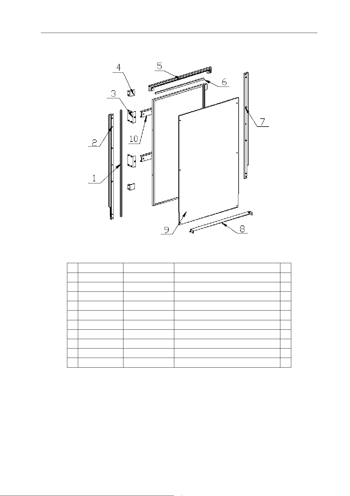
Lane Master Pro GMP Manual
9.4 Monitor assy.
No. Part No. Code No. Name Qty
1 L114-127-000 20611605E014
2 L114-131-000 20611605E005
3 L114-114-000 20211605E006
4 L114-135-000 20211605E014
5 L114-129-000 20611605E003
6 L114-128-000 20611605E015
7 L114-130-000 20611605E004
8 L114-119-000 20211605E010
9 L114-702-000 20511605E002
10 L114-113-000 20211605E005
Vertical bar 2
Side light plastic 1
Monitor fixed bracket 4
Monitor fixed plate 4
Side light plastic 1
Horizontal bar 2
Side light plastic 1
Monitor down cover 1
Monitor cover plastic 1
Monitor mounting bar 2
26
07/12/2018
Page 28
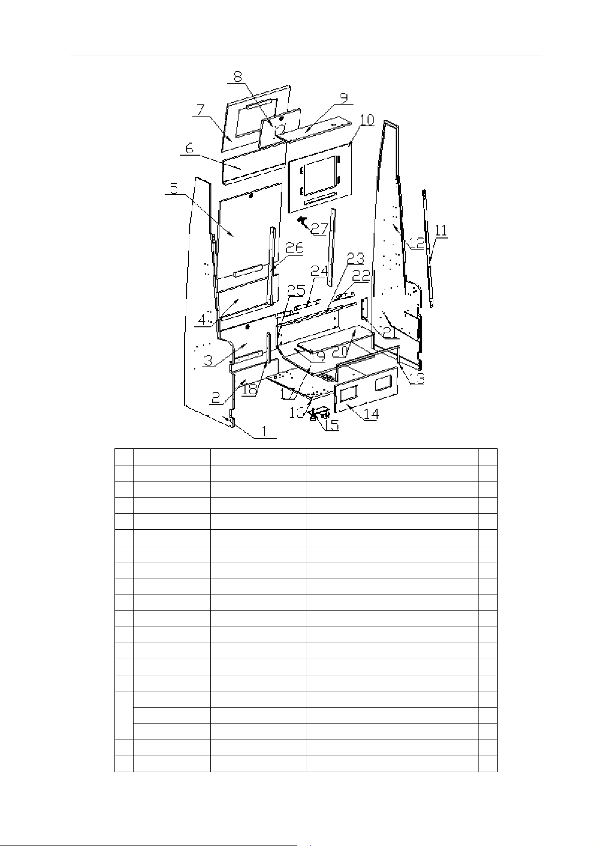
Lane Master Pro GMP Manual
No. Part No. Code No. Name Qty
1 L114-510-000 20311605E009
2 L114-528-000 20311605E027
3 L114-530-001 20311605E029A
Power supply connect plate 1
L side plate 1
Down service door 1
4 L114-535-000 20311605E034 Back bottom door connect plate 1
5 L114-529-000 20311605E028
6 L114-532-000 20311605E031
7 L114-536-000 20311605E035
8 L114-533-000 20311605E032
9 L114-534-000 20311605E033
10 L114-531-000 20311605E030
11 L114-503-000 20311605E002
12 L114-509-000 20311605E008
13 L114-109-000 20211605E001
14 L114-513-000 20311605E012
Top service door 1
Back top plate 1
Fan door 1
Fan plate 1
Top plate 1
Back middle plate 1
Monitor wood plate 2
Side plate 1
Back reinforced plate 1
Front bed plate 1
L114-101-000 20241708002 Caster plastic 4
15
L114-738-000 25501000003
L114-177-000 26000008000
16 L114-502-000 20311605E001
17 L114-514-000 20311605E013
Rear Lane bed plate 1
Castor 4
Cabinet leveller 4
Bed plate 1
27
07/12/2018
Page 29
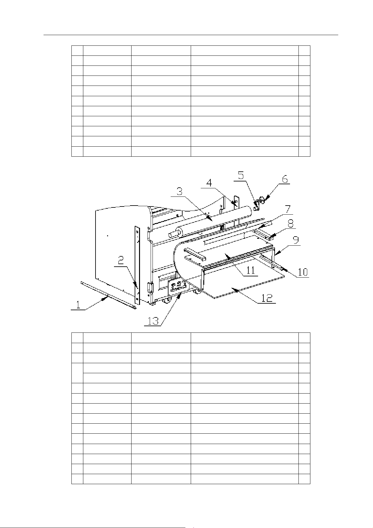
Lane Master Pro GMP Manual
18
No. Part No. Code No. Name Qty
L114-515-000 20311605E014
19 L114-506-000 20311605E005
20 L114-526-000 20311605E025
21 L114-112-000 20211605E004
22 L114-111-000 20211605E003
23 L114-504-000 20311605E003
24 L114-110-000 20211605E002
25 L114-505-000 20311605E004
26 L114-516-000 20311605E015
27 L114-736-000 25300171001 Lock 3
Door fixed plate 2
Lane plate 1
Rear lane plate 1
Back reinforced plate 2 2
Back reinforced plate 2
Rear Lane back plate 1
Wood connect plate 1
Lane plate 1
Up door fixed plate 2
28
07/12/2018
No. Part No. Code No. Name Qty
1 L114-116-000 20211605E008
Side angle bead 4
2 L114-136-000 20211605E015 Connecting plate 2 (vertical) 1
L114-117-000 20211605E033
Protect bar 1
3
L114-171-000 29911605003A
4 L114-115-000 20211605E007
5 L114-120-000 20211605E011
6 L114-118-000 20211605E009
7 L114-132-000 20611605E016
8 L114-134-000 20611605E006
9 L114-126-000 20211605E013
Connecting plate(vertical) 1
Protect bar connecting rod 2
Damping fixed bracket 2
Lane side light plastic 2 2
Black vinyl 1
Damping foam 1 1
Lane reinforced board 1
10 L114-173-000 20211605017 Foam pressing plate 2
11 L114-172-000 20211605016 Damping foam fixed bar 1
12 L114-133-000 20611605E010
13 L114-137-001 20211605E036A
Rear Lane back board 1
Post fix plate 1
Page 30
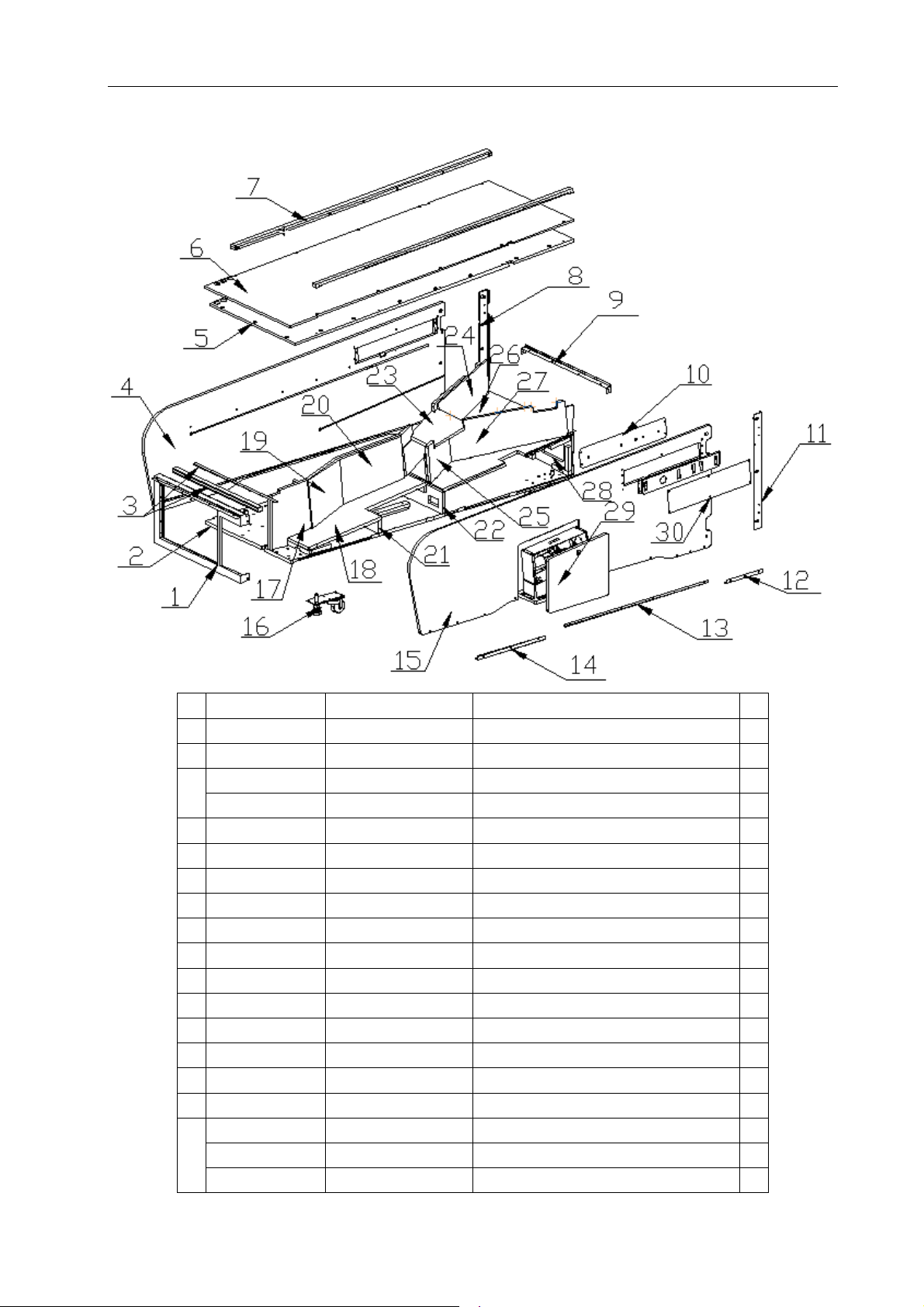
9.5 Lane assy.
Lane Master Pro GMP Manual
No. Part No. Code No. Name Qty
1 L114-139-000 20211605E017
2 L114-507-000 20311605E006
L114-155-000 20611605E018
3
L114-156-000 20211605E032
4 L114-512-001 20311605E011A
5 L114-508-000 20311605E007
6 L114-527-000 20311605E026
7 L114-163-001 20611605E011A
8 L114-159-000 20211605E024
9 L114-109-000 20211605E001
10 L114-154-000 20211605E034
11 L114-158-000 20211605E023
12 L114-161-000 20211605E026
13 L114-160-000 20211605E025
14 L114-162-000 20211605E027
15 L114-511-000 20311605E010
L114-101-000 20241708002 Caster plastic 4
16
L114-738-000 25501000003
L114-177-000 26000008000
Door frame 1
Front bed plate 1
Protect bar 1
Protect bar insert part 1
Side plate 1
Connected plate 2
Lane plate 1
Lane side light plastic 2
Side reinforced plate 1
Back reinforced plate 1
Sensor cover 2
Side reinforced plate 1
Side angle bead 2
Side angle bead 2
Side angle bead 2
Side plate 1
Castor 4
Cabinet leveller 4
29
07/12/2018
Page 31
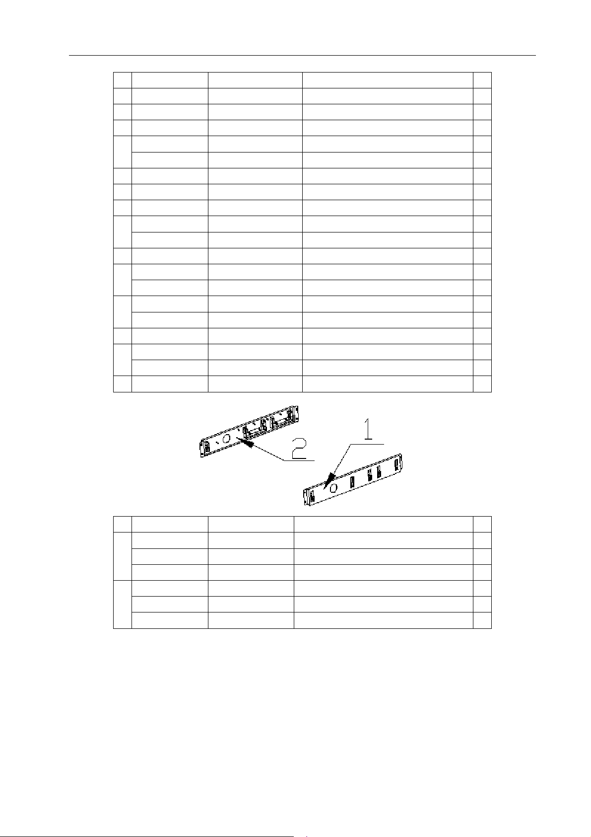
Lane Master Pro GMP Manual
17
No. Part No. Code No. Name Qty
L114-537-000 20311605E036
18 L114-538-000 20311605E037
19 L114-539-000 20311605E038
L114-523-000 20311605E022
20
L114-143-000 20611605E023
21 L114-524-000 20311605E023
22 L114-525-000 20311605E024
23 L114-522-000 20311605E021
L114-521-000 20311605E020
24
L114-140-000 20611605E020
25 L114-520-000 20311605E019
L114-518-000 20311605E017
26
L114-142-000 20611605E022
L114-519-000 20311605E018
27
L114-141-000 20611605E021
28 L114-517-000 20311605E016
L114-540-000 20311605E039
29
L114-736-000 25300171001 Lock 1
30 L114-157-000 20211605E020
Bottom-Lane side plate 1
Bottom-Lane front plate 1
Bottom-Lane middle plate 1
Middle side plate 1
Damping foam 3 1
Small plate 1
Large plate 1
Lane cover plate 1
Front side plate 1
Damping foam 1
R side plate(short) 1
Lane back plate 1
Lane foam 1
R side plate(long) 1
Damping foam 2 1
Rear cover board 1
Ball out cover 1
Sensor cover 2
30
07/12/2018
No. Part No. Code No. Name Qty
L114-175-000 20211605021
1
L114-315-000 20101020159 Cross recessed hexagon screw set 5
Sensor fixed plate 2 1
L114-330-000 20102020034 Non-metallic hexagon lock nut 5
L114-174-000 20211605019
2
L114-315-000 20101020159 Cross recessed hexagon screw set 5
Sensor fixed plate 1
L114-330-000 20102020034 Non-metallic hexagon lock nut 5
Page 32
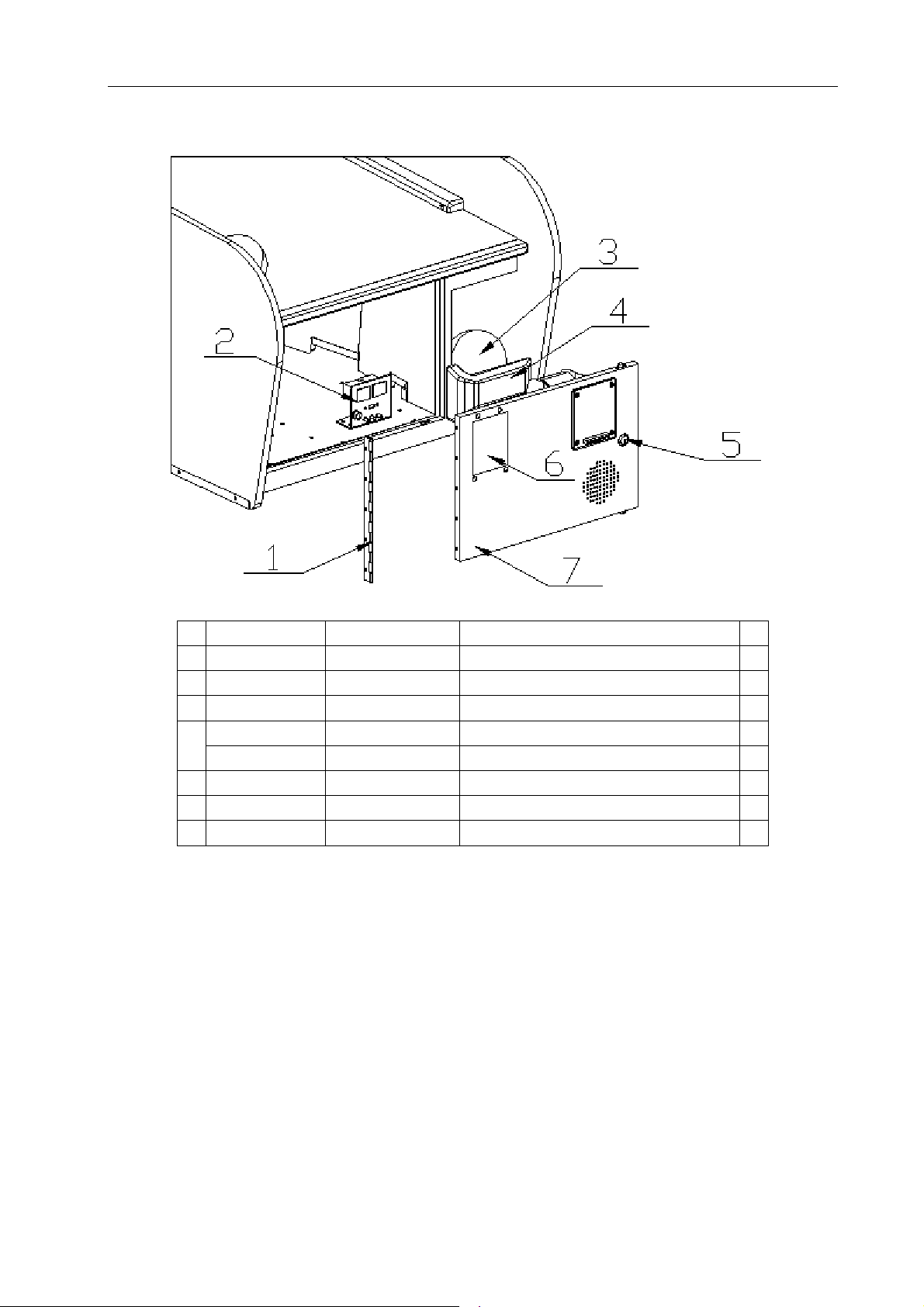
Lane Master Pro GMP Manual
No. Part No. Code No. Name Qty
1 L114-144-000 20211605E031
2 L114-107-000 20211605H001
3 L114-170-000 20611605027A
L114-145-000 20611605E017
Ticket Meter bracket 1
Hinge 1
Bowling ball 2
Ball hopper 1
4
L114-146-000 20611605E019
5 L114-104-000 20211605H003
6 L114-106-000 20211605H005
7 L114-103-000 20211605H002
Light plastic 1
Lock plate 1
DBV cover plate 1
Door plate 1
07/12/2018
31
Page 33
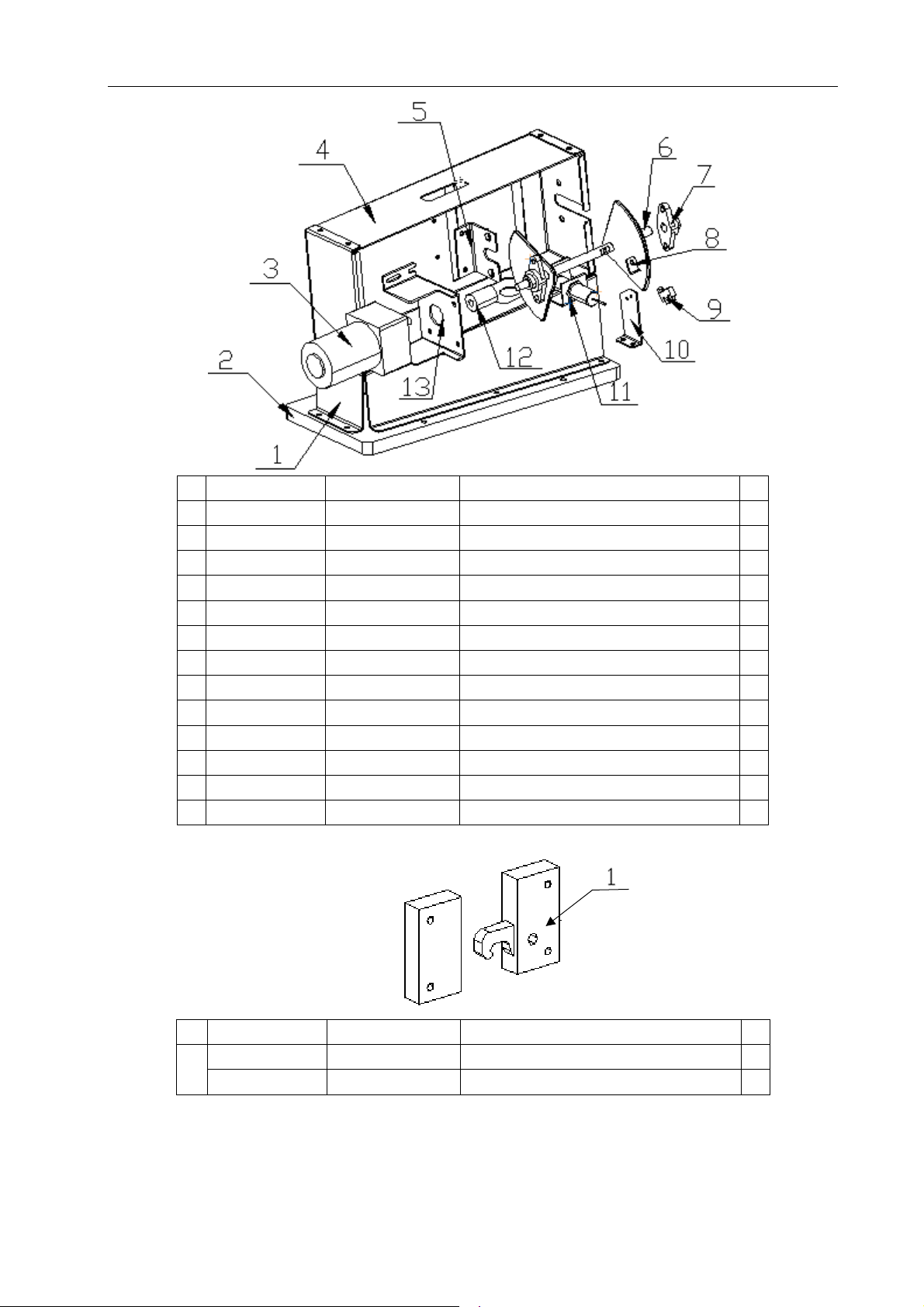
Lane Master Pro GMP Manual
No. Part No. Code No. Name Qty
1 L114-541-000 20311605E040
2 L114-151-000 20211605E042
3 L114-734-000 23404000093
4 L114-147-000 20211605E038
5 L114-149-000 20211605E040
6 L114-150-000 20211605E041
7 L114-731-000 20106130014
8 L114-153-000 20211605E044
9 L114-733-000 22604000073
10 L114-152-000 20211605E043
11 L114-176-000 20211605049
12 L114-732-000 20117000401
13 L114-148-000 20211605E039
Cabinet support plate 1
Base 1
DC geared motor 1
Frame 1
Shaft fixed plate 1
Spindle 1
Diamond br 2
Sensor pressing plate 1
Micro SW 1
SW fix plate 1
Sensor fixed plate A 1
Coupling 1
Motor bracket 1
No. Part No. Code No. Name Qty
L114-735-000 25300000148
R5 lock 4
1
L114-306-000 20101010025 Cross recessed pan head screw 16
32
07/12/2018
Page 34
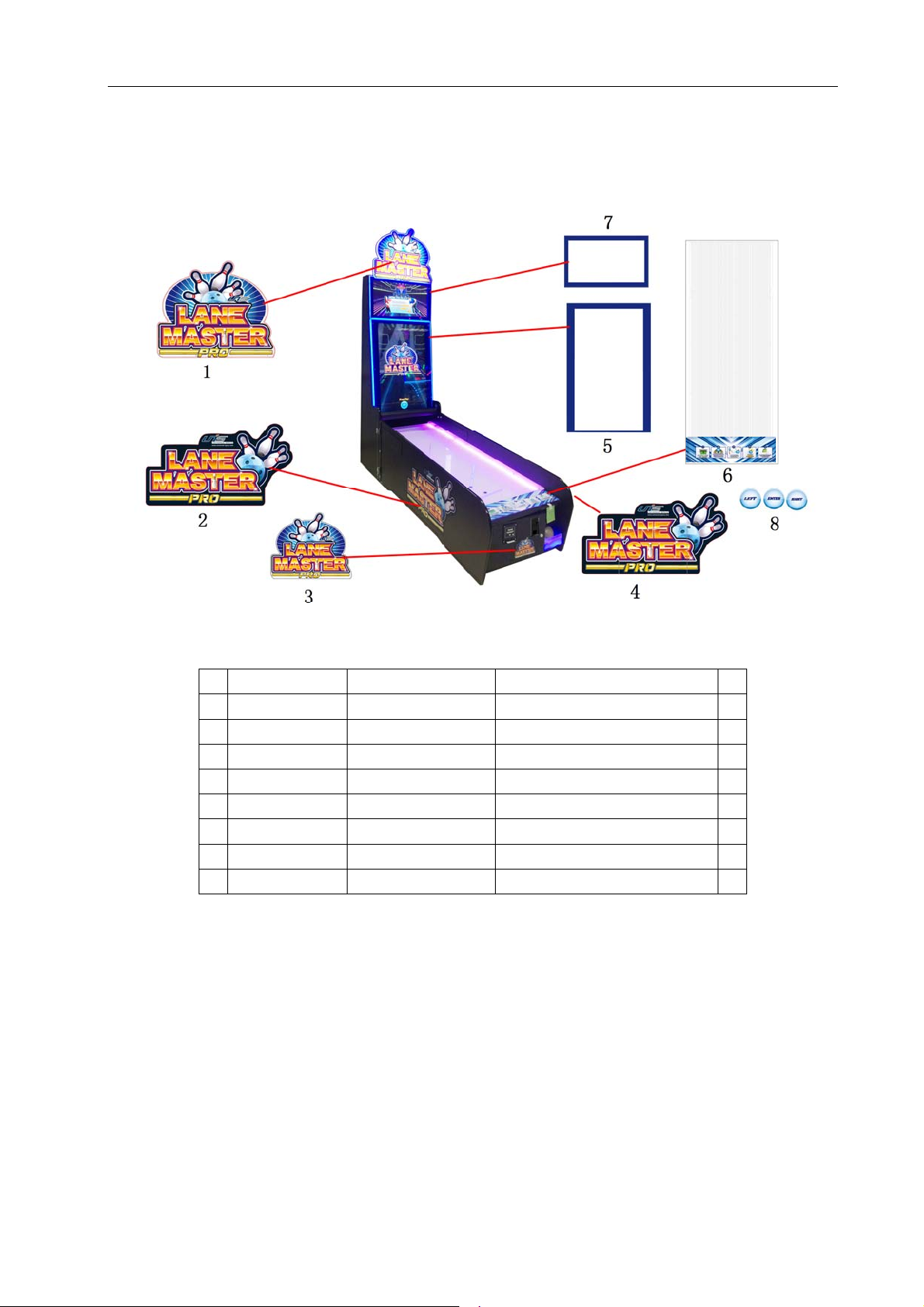
9.6 Decals
Lane Master Pro GMP Manual
No. Part No. Code No. Name Qty
1 L114-713-000 20511605E003
2 L114-709-000 20511605F004
3 L114-710-000 20511605F005
4 L114-708-000 20511605F003
5 L114-702-000 20511605E002
6 L114-701-000 20511605E001 Monitor cover plastic(small) 1
7 L114-703-001 20511605H001A
8 L114-704-000 20511605H002
Marquee decal 1
Side plate L plastic 1
Door frame decal 1
Side plate R plastic 1
Monitor cover plastic 1
Lane clear plastic 1
Button decal 1
07/12/2018
33
Page 35
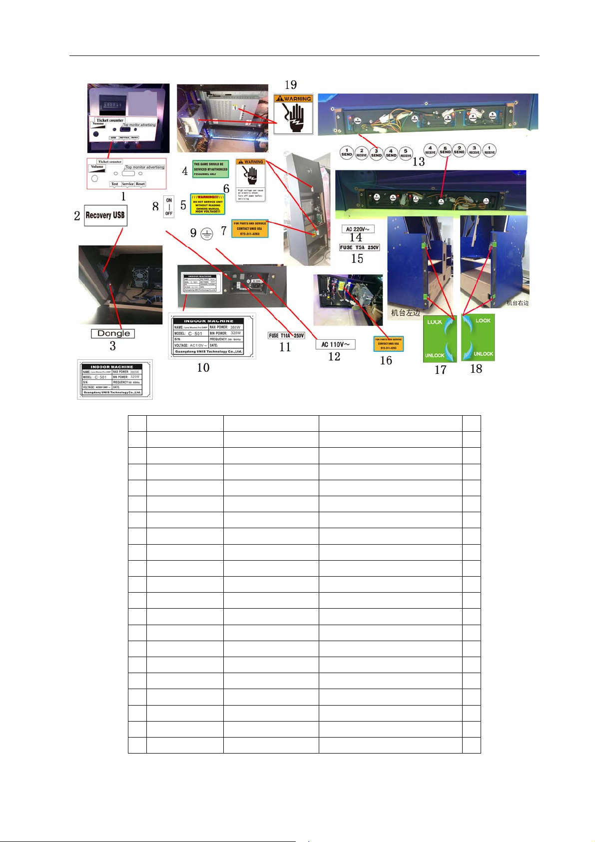
Lane Master Pro GMP Manual
20
No. Part No. Code No. Name Qty
1 L114-707-000 20511605H005
2 L114-717-000 26601100283
3 L114-728-000 25600000093
4 L114-721-000 25600000042
5 L114-722-000 25600000067
6 L114-720-000 25600000037
7 L114-729-000 25600000095
8 L114-715-000 20511605D016A
9 L114-727-000 25600000091
10 L114-705-001 20511605H003A
11 L114-726-000 25600000077 Fuse label 1
12 L114-723-000 25600000071 110V label 1
13 L114-711-000 20511605F008
14 L114-724-000 25600000072
15 L114-725-000 25600000074 Fuse label 1
16 L114-730-000 25600000096
17 L114-715-000 20511605D016A
18 L114-716-000 20511605D017A
19 L114-719-000 25600000036
20 L114-706-001 20511605H004A
Meter label 1
USB label 1
Dongle label 1
Service label 1 1
Service label 1
Warning label L 1
Service label (L) 1
Lock label 1 1
GND label 1
110V nameplate 1
Sensor label 1
220V label 1
Service label (S) 1
Lock label 1 2
Lock label 2 2
Warning label S 2
220V nameplate 1
34
07/12/2018
Page 36
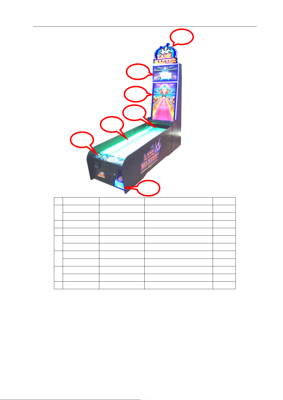
Lane Master Pro GMP Manual
9.7 Electrical components
5
6
No. Part No. Code No. Name Qty
L114-415-000 22002013004
1
L114-417-000 22002015005
2 L114-416-000 22002013013 5050 light strip-blue 1.95M
3 L114-416-000 22002013013 5050 light strip-blue 2.5M
L114-414-000
4
L114-414-000 22002013002
L114-414-000
5
L114-414-000 22002013002
L114-418-000 22401000066 White button 3
6
L114-424-000 22604000006
7 L114-416-000 22002013013 5050 light strip-blue 0.5M
22002013002
22002013002
2
3
4
7
1
LED light strip-blue 1.95M
5051 light strip-white 1.95M
RGB light strip 0.2M
RGB light strip 0.2M
RGB light strip 2M
RGB light strip 2M
Micro SW 3
07/12/2018
35
Page 37
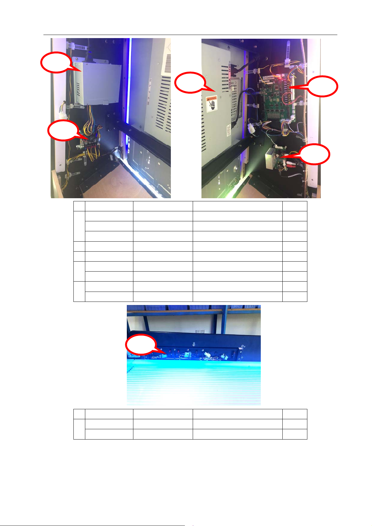
Lane Master Pro GMP Manual
1
2
3
No. Part No. Code No. Name Qty
L114-410-000 21602000001A
1
L114-432-000 23301018002 Power cord (0.5m) 1
L114-441-000 23307020001 DVI-DVI video cable 1
2 L114-405-000 21201042002 42" LED monitor 1
3 L114-443-000 29711605001 Short cut protect board 1
L114-444-000 29741702003 Main board 1
4
L114-442-000 23309000263D
L114-428-000 22803000031
5
L114-439-000 23305000003
Power supply 1
Cable set 1
2.0 amplifier 1
Audio cable 1
4
5
1
No. Part No. Code No. Name Qty
L114-409-000 21503000053
Sensor SW(receive) 5
1
L114-408-000 21503000052
36
07/12/2018
Sensor SW(send) 5
Page 38
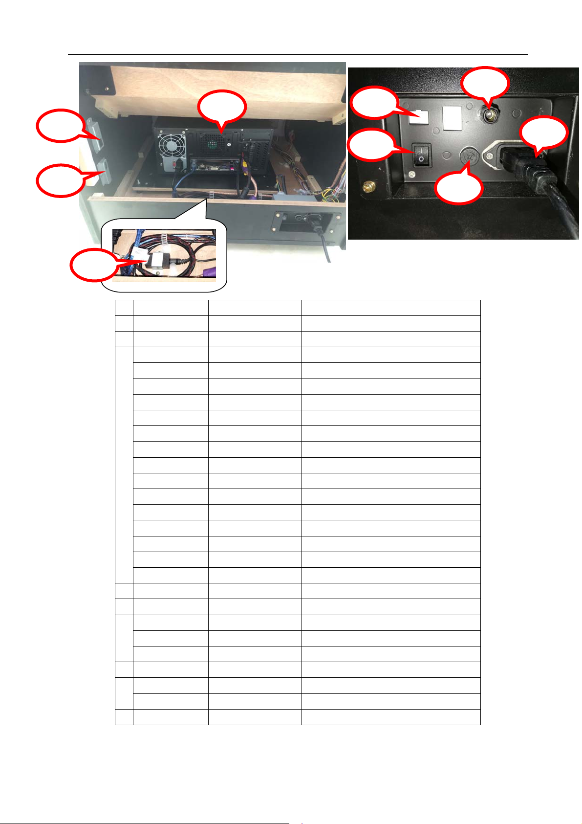
Lane Master Pro GMP Manual
5
1
2
3
8
7
4
6
9
No. Part No. Code No. Name Qty
1 L114-446-000 41300000007 USB 1
2 L114-403-000 21107020036 Dongle 1
L114-402-000 21102000051B
PC assy.(TUV) 1
L114-402-001 21107220008 Main board 1
L114-402-002 21107190017 CPU 1
L114-402-003 21107090013 Memory 1
L114-402-004 21107060004 Hard disk 1
L114-402-005 21107170012 PC power supply 1
L114-402-006 21107070007 CPU fan 1
3
L114-402-007 21107070008 Cabinet fan 1
L114-402-008 21107030081 Video card 1
L114-402-009 21107270004 Cabinet 1
L114-432-000 23301018002 Power cord (0.5m) 1
L114-435-000 23304000098
L114-438-000 23304030001
USB cable 1
USB cable 1
L114-436-000 23304010027 USB cable 1
L114-437-000 23304010032
4 L114-423-000 22601000005
USB cable 1
Rocket SW 1
5 L114-406-000 21412000001 Binding post 1
L114-401-000 21902000006
6
L114-411-000 21901000012 Fuse(220V) 1
Fuse bracket 1
L114-412-000 21901000013 Fuse(110V) 1
7 L114-431-000 23301018001 Power cord (1m) 1
L114-433-000
23302000001
Network cable bracket 1
8
L114-434-000 23302000003
9 L114-429-000 22807000002
Network cable 1
Audio isolator 1
07/12/2018
37
Page 39
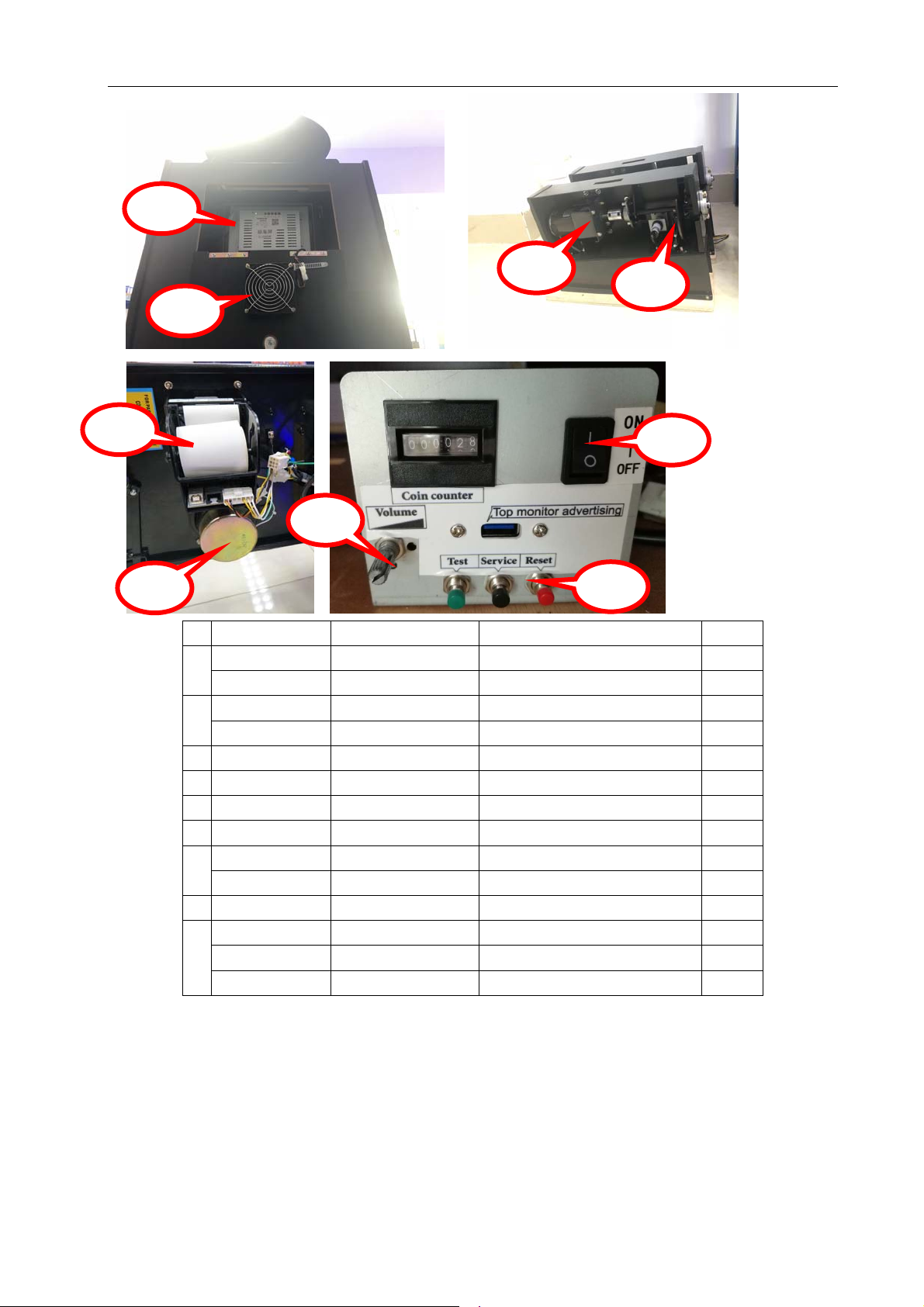
Lane Master Pro GMP Manual
1
2
3
4
5
8
7
6
9
No. Part No. Code No. Name Qty
L114-440-000 23307010001 DVI-HDMI video cable 1
1
L114-404-000 21201027001 27" Monitor 1
L114-425-000 22702000010 Fan net 2
2
L114-426-000 22702010025 Fan 1
3 L114-734-000 23404000093
4 L114-407-000 21503000034
DC geared motor 1
Sensor SW 1
5 L114-901-000 21107180018 Printer 1
6 L114-427-000 22801000085
L114-422-000
22403000001 POT 1
Speaker 1
7
L114-445-000 29791400001 POT connect board 1
8 L114-423-000 22601000005
L114-419-000
9
L114-420-000 22402030002
22402010002 Button-red 1
Rocket SW 1
Button-green 1
L114-421-000 22402050001 Button-black 1
38
07/12/2018
Page 40
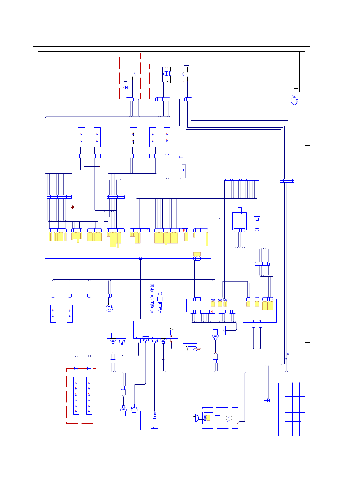
Lane Master Pro GMP Manual
10. WIRING DIAGRAM
D
8
7654321
Lane R side light
JSBD -PX-18
J20
RGB
LEDLED
200mm
RGB
12V 12V
Lane L side light
24102030241020
124
3
P
123
4
C
J19
241020
30
12VRG
200mm
12VRG
124
123
B
LEDLED
B
30
3
P
4
C
103040
A0×2
24×2
JSBD .R -PX-12
123456789
123456789
J17
1020304050
A02024
50
80
45Q
60
70
P
1011121314
1011121314
C
60
10M
80
91
70
45Q
JSBD -PX-19
10×2
20×2
30×24060
24×2
24×2
123456789
123456789
J18
JSBD -PX-16
1020304050
40P
40P
24
102030
JSBD .R -P X-11
40A030
123456789
123456789
J26
GND
Tik m e ter
Coin meter
70
50
60
GND
Test b tn
Setting btn
10
24
80
5557/10 P
5557/6P
1234567
12345
6
10
10
J27
12V
Reset btn
12345
DBV
Coin lock
1234567
6
J25
投币
12V
12V
GND
2 Tik fb
2 Tik driver
Out of tik light
M3-MB.PCB
Ver1.1
10×2
20×2
30×24050
24
10M
91
5557/8P
8
123456789
8
123456789
J21
12V
12V
12V
GND
GND
Tik fb
Tik d r i ver
Motor d riv er
Lane side red light
Lane side red light
Lane side green light
24
A0
24
1
J10
1
24
12V
A0
2
1
2
C
J09
2
1
2
P
A0
24
A0
GND
12V
GND
A0P
40P
1
2
C
P
C
J08
1
2
P
JSBD -PX-05
A0×2
24×2
12V
GND
Blue 5050 light 1950MM
27" Monitor side light
12V
GND
Blue 5050 light 2500MM
42" Monitor side light
JSBD -P X-06
A0
24
1
2
C
J07
1
2
P
A0
A0
FAN
Fan
12V
42" Monitor
A0P
50P
A0
24
A0
24
1
2
1
2
C
1
J12
24
12V
C
2
1
2
P
J11
P
A0
A0
24
GND
12V
GND
JSBD -PX-07
90P
JSBD -PX-03
HF
123
J04
123
HM
10P
45Q
60P
Blue 3528 light 1950MM
White 5050 light 1950M M
Marquee light
D
C
B
A
V1.0
SW S PDT
Electromagnet
Lane R s ide light
JSBD -PX-15
J22
10
1111
10
12VRG
2000mm
12VRG
102030
24
124
123
102030
24
VH
Coin meter
20
A0
1234567
1234567
J27
246070
403050
B
LEDLED
Ball outlet light
B
3
P
4
C
10M
20M
30M
40M
123456789
123456789
J20
Lane s ensor 1
Lane s ensor 2
Lane s ensor 3
Lane s ensor 4
GND
A0
A0
50M
Lane s ensor 5
JP Coin mech.
IN400 7
D1
10
A0
24
80
123
4
JSBD .R -PX-13
P
123
4
J26
C
45Q
A01024
80
12VRG
B
LEDLED
2000mm
12VRG
B
102030
24
124
3
P
123
4
J21
C
Lane L side light
102030
24
10
P
10
C
60
60
102030
VH
123456789
10
123456789
10
J22
12V
12V
12V
L bt n
R bt n
Ball out l e t l ight
Control panel blue light
Comfirm btn light
USB-B
Blue light (500MM)
60M
S1S2S3
Test
Setting
102030
12V
12V
24
1
1
J24
24
70M
Motor position
Motor-ball ou tlet
Reset
P
8
8
C
GND
GND
A0
2
P
2
C
60
91M
92M
80M
Ball sensor
Comfirm btn
JSBD -PX-14
45Q
J25
93M
94M
95M
10111213141516
10111213141516
L bt n
R bt n
Tik er ro r
Tik payout
SW
SW DPS T
JSBD.R-PX-00-01
28-Apr-2018
Lane master wiring diagram 1(JP)
Date:
Name:
10P
10P
45Q
60P
1234567
1234567
10P
10P
45Q
60P
Version:
Un iv er s a l Sp a ce
Amusement machine
UNIS
60P
8
C6201HF-2*4P
8
60P
C6201HM-2*4P
Meter assy.
10P
60P
10P
60P
HF
123
4
123
4
J28
10P
60P
10P
60P
C6201HM-2*2P
1
2
C
40
24
D1
IN4007
J16
123456789
A0P
40P
10M
20M
30M
40M
Sensor assy. connecting part
1011121314151617181920
60M
70M
50M
91M
80M
92M
C
93M
94M
95M
102030
40
JSBD -PX-10
J02
JSBD -PX-17
VR
40
XH
1234567
8
YY1820D-H26
1234567
2525
2626
GND
GND
8
J15
GNDTik printer signal
12V
12V
12V
GND
GND
J1
123
4
123
4
VH
A0P
A0P
40P
40P
50K POT
J15
20M
JSBD -PX-09
CN1
12345
12345
50M
40M
Speaker
+
-
VRP CB
90
50
1
2
6
P
6
1
2
J14
C
XH
A0ME60M
A0ME60M
50M
40M
20M
90
50
1234567
8
P
1234567
8
J13
C
A0ME60M
50M
40M
20M
90
50
JSBD -PX-04
Video port
DONGLE
USB-A
DVI p ort
HDMI port
10P
45Q
60P
123
HM
J05
123
HF
A0P
50P
90P
USB-A
USB-A
DVI p ort
PC assy.
Audio port
A0P
50P
90P
Wiring for tik p rinter
DVI p ort
27" Monitor
Network cable
C
A0P
A0P
40P
40P
A0P+A0×3
40P+24×3
40P×2
A0P
40P
A0P
VH
124
3
123
4
J1
P2
P1
123
4
16
77
123
4
16
P
A0O
50
A0P
A0P
40P
40P
A0O
Audio is olator
Audio port
PLUG
40P
J2
12V
12V
12V
GND
GND
GND
P3
P4
123
4
123
15
11
10
1717
15
11
10
2424
40O
40O
A0O
4
123
4
123
4
40O
A0O
A0O
20O
40O
A0O
A0O
20O
JHD5084HP/4P
JHD5084HP/4P
Power s upp ly
A0P
50P
90P
HF
123
J03
123
HM
10P
45Q
60P
Noise filter
FUSE
Power SW
SW D PST
T10 A/1 10V
L
E
N
Earth
B
JSBD -P X-08
90
50
A0ME60M
50M
40M
20M
A0P
40P
VH
1
1
2
VH
1
1
2
CN-9
CN-4
L+
12V
GND
Audio input L
R
45Q
XH
2
12345
6
2
12345
6
L-
CN-3
GND
GND
L channel 1
L channel 2
R ch annel 1
R ch annel 2
Audio output
Audio input R
W
10P
60P
JSBD -PX-02
±10
±20
±30
±40
±50
:
Example 2 0 m
10P
45Q
60P
HF
123
J01
123
HM
10P
45Q
60P
JSBD -PX-01
Color o f the wire: 20 mea n s red
Size of the wire: m means AWG2 4 UL10 07
white
Note: Wire color and wire size is sho wn in cod e.
A
Tolerance
0~1000
1001~2 00 0
2001~3 00 0
3001~4 00 0
4001~5 00 0
unit mm
scale
AWG30 UL1007
AWG28 UL1007
AWG26 UL1007
AWG24 UL1007
AWG22 UL1007
AWG20 UL1007
AWG18 UL1007
AWG16 UL1007
JKLMNOP
Q
Wire si ze co de
1 2 3 4 5 6 78
black
pink
light gre en
sky blue
shield layer
ABCDEFGHI
brown
red
orange
yellow
green
blue
violet
grey
123456789
W ire color code
39
07/12/2018
Page 41
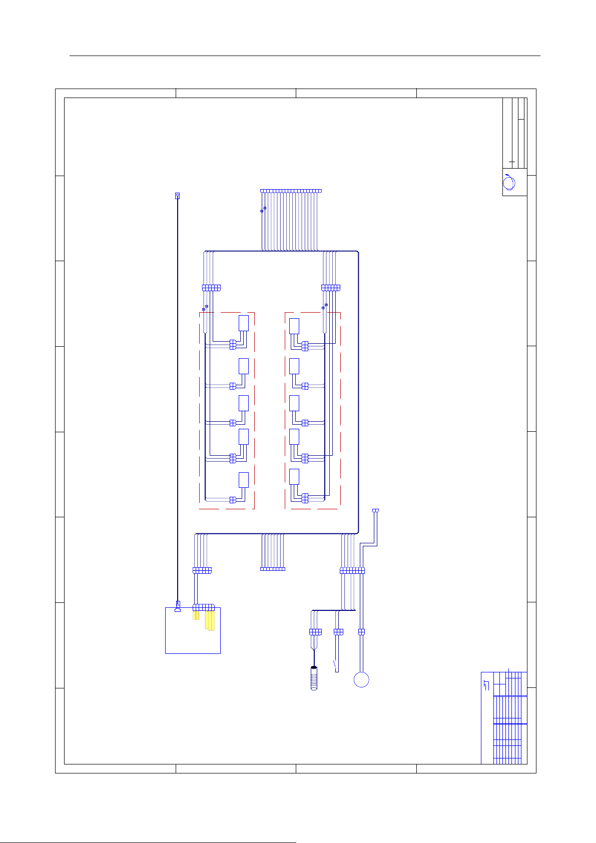
Lane Master Pro GMP Manual
8
D
C
B
A
V1.0
JSBD.R-PX-00-02
28-Apr-2018
Lane master wir ing diagram 2 (J P)
Date:
Name:
Version:
Univ ersa l Sp a ce
123456789
J16
A0P
10M
20M
30M
40P
40M
60M
70M
50M
1011121314151617181920
91M
92M
93M
80M
94M
95M
102030
P
40
Amusement machine
UNIS
7654321
24×5
A0×5
JSBD .R -PX-20
20M
50M
A0
24
12345
J29
12345
24
6
C
6
P
20M
50M
A0
J30
A0
24
12345
12345
A0
24
40M
10M
30M
C
6
6
P
40M
10M
30M
JSBD -PX-22
JSBD -PX-21
24×5
A0×5
10M
A0M
60M
C
L side sensor
P
3
3
50M
2
2
A0
1
1
24
J38
Sensor s end 4 Sen sor receive 5
10M
60M
C
P
2
2
A0
1
1
24
J37
Sens or send 3
10M
60M
C
P
2
2
A0
1
1
24
J36
Senso r receive 2
C
10M
A0M
60M
P
3
3
20M
2
2
A0
1
1
24
J35
Sensor send 1
10M
60M
C
P
2
2
A0
1
1
24
J34
10M
10M
10M
Ball testing
10M
10M
24×5
A0×5
Sens or receive 4
R side sensor
C
P
A0M
60M
3
3
40M
2
2
A0
1
1
24
J44
Senso r send 5
60M
C
P
2
2
A0
1
1
24
J43
Sens or send 2
60M
C
P
2
2
A0
1
1
24
J42
Senso r receive 3
C
P
A0M
60M
3
3
30M
2
2
A0
1
1
24
J41
Senso r receive 1
A0M
60M
C
P
3
3
10M
2
2
A0
1
1
24
J40
1
2
J25P
5557/2P
40
24
40
07/12/2018
70M
A0
24
60M
80M
40
24
1234567
8
P
1234567
8
J31
C
70M
A0×22480M
40
24
A0
70M
40
24
C
123
1
C
P
J46
2
C
J47
1
2
123
P
A0
P
70
20
A0
J33
JSBD .R -PX-25
CN1
94M
A0
244095M
12345
12345
A0
24
1234567
1234567
GND
12V
91M
92M
93M
A0
243020
10
1234567
6
C
6
P
VH
Tik er ro r
Printer signal
Tik payout
8
J32
C
JSBD -PX-23
80M
A0
24
123
4
123
4
J45
60
10
A0
Tik prin ter (cust omer install )
JSBD -P X-24
D
C
Moto r bal l ou t
Ball sensor
E3F -MLS1 0C 4
M
Example 2 0 m
Send ball motor
Color o f the wire: 20 mean s red
Size of the wire: m means AWG24 UL1007
B
Note: Wire color and wire size is sho wn in cod e.
A
±10
±20
±30
±40
±50
:
Tolerance
0~1000
1001~2 00 0
2001~3 00 0
3001~4 00 0
4001~5 00 0
unit mm
scale
AWG30 UL1007
AWG28 UL1007
AWG26 UL1007
AWG24 UL1007
AWG22 UL1007
AWG20 UL1007
AWG18 UL1007
AWG16 UL1007
JKLMNOP
Q
Wire si ze code
1 2 3 4 5 6 78
black
pink
light green
sky blue
shield layer
ABCDEFGHI
brown
red
orange
yellow
green
blue
violet
grey
white
123456789
Wire color code
 Loading...