

Page 1

USI 802.11b WLAN
CF Card
Quick User Guide
Page 2

Special Issue Regarding to the Configurations of the WLAN CF Card
This WLAN CF Card, is designed and classified as a HAND-HELD device. It is
designed to be adapted with the hand-held device such as PDA, PocketPC,
Palm etc. The configuration other than these usage (e.g. with the body-worn
manner) is not intended by the manufacturer and is strictly prohibited. In
addition, for your own safety, it is recommended that keeping at least 20cm
separation between the device and your body to minimize the possible RF
exposure.
This device must not be co-located or operating in conjunction with any
other antenna or transmitter in order to avoid mutual interference.
Page 3

Index
1. Introduction..................................................................................................................... 4
1.1 Network Scenarios................................................................................................ 4
1.2 Features................................................................................................................. 4
2. Installing and Configuring the Wireless Network for Pocket PC................................... 6
2.1 Preparation ............................................................................................................ 6
2.2 Installing the Driver and Utility from a CDROM................................................ 6
2.3 Configuring the Wireless Network in Windows CE............................................ 8
3. Using the Client Manager Utility.................................................................................. 15
3.1 Installing the Client Manager ............................................................................. 15
3.2 The meaning of Tack Tray Icons........................................................................ 15
3.3 Using the Client Manager ................................................................................... 15
4. Card Specifications ....................................................................................................... 18
4.1 Physical Specifications ....................................................................................... 18
4.2 Power Characteristics ......................................................................................... 18
4.3 Networking Characteristics................................................................................. 18
4.4 Radio Characteristics .......................................................................................... 19
Basic Troubleshooting ...................................................................................................... 21
Page 4

Index of Flow Chart
Figure 1 ............................................................................................................... 5
Figure 2 ............................................................................................................... 7
Figure 3 ............................................................................................................... 8
Figure 4 ............................................................................................................... 9
Figure 5 ............................................................................................................. 11
Figure 6 ............................................................................................................. 12
Figure 7 ............................................................................................................. 13
Figure 8 ............................................................................................................. 14
Figure 9 ............................................................................................................. 16
Figure 10 ........................................................................................................... 16
Figure 11 ........................................................................................................... 17
Page 5

1. Introduction
Wireless LAN is local area networking without wires, which uses radio
frequencies to transmit and receive data between PC’s or other network
devices without wires or cables. Wireless LAN configurations include
independent networks suitable for small or temporary peer-to-peer
configurations and infrastructure networks, offering fully distributed data
connectivity via micro cells and roaming.
The USI 802.11b WLAN CF card allows Pocket/Handheld PC
(Windows CE 3.0 or 4.0) devices to connect to a Wi-Fi
wireless local area network (LAN), or communicate directly with other
devices enabled for wireless LAN connectivity.
The USI 802.11b WLAN CF card is designed to meet the mobility,
performance, security, interoperability, management, and reliability
requirements of IEEE 802.11b high data rate standard.
1.1 Network Scenarios
1.2 Features
TM
IEEE 802.11b
Features includes:
• CompactFlash
TM
form factor fits devices with CF Type I and Type II
extended card slots
• Functions with Pocket/Handhelp PC (Windows CE 3.0 or 4.0) devices
with CF Type I and Type II extended card slots
• Compliant with 11 Mbps 802.11b high-speed specification
• Data rate 11/5.5/2/1 Mbps automatic fallback under noisy environment
• Power Management for decreased power consumption
• Interoperable with IEEE 802.11b compliant equipment
• Supports full mobility and seamless roaming from cell to cell
• User-friendly client manager utility
• Supports 64 and 128-bit WEP (Wired equivalent privacy).
• Direct Sequence Spread Spectrum (DSSS) technology provides robust,
• interference-resistant and secure wireless connection.
• Wireless connection without the hassles and cost of cabling.
• Greater flexibility to locate or move networked device
• The USI 802.11b WLAN CF Card has only one LED indicators
o Transmit/Receive (flashing green)
o Power ON/OFF LED(flashing red)
Page 6
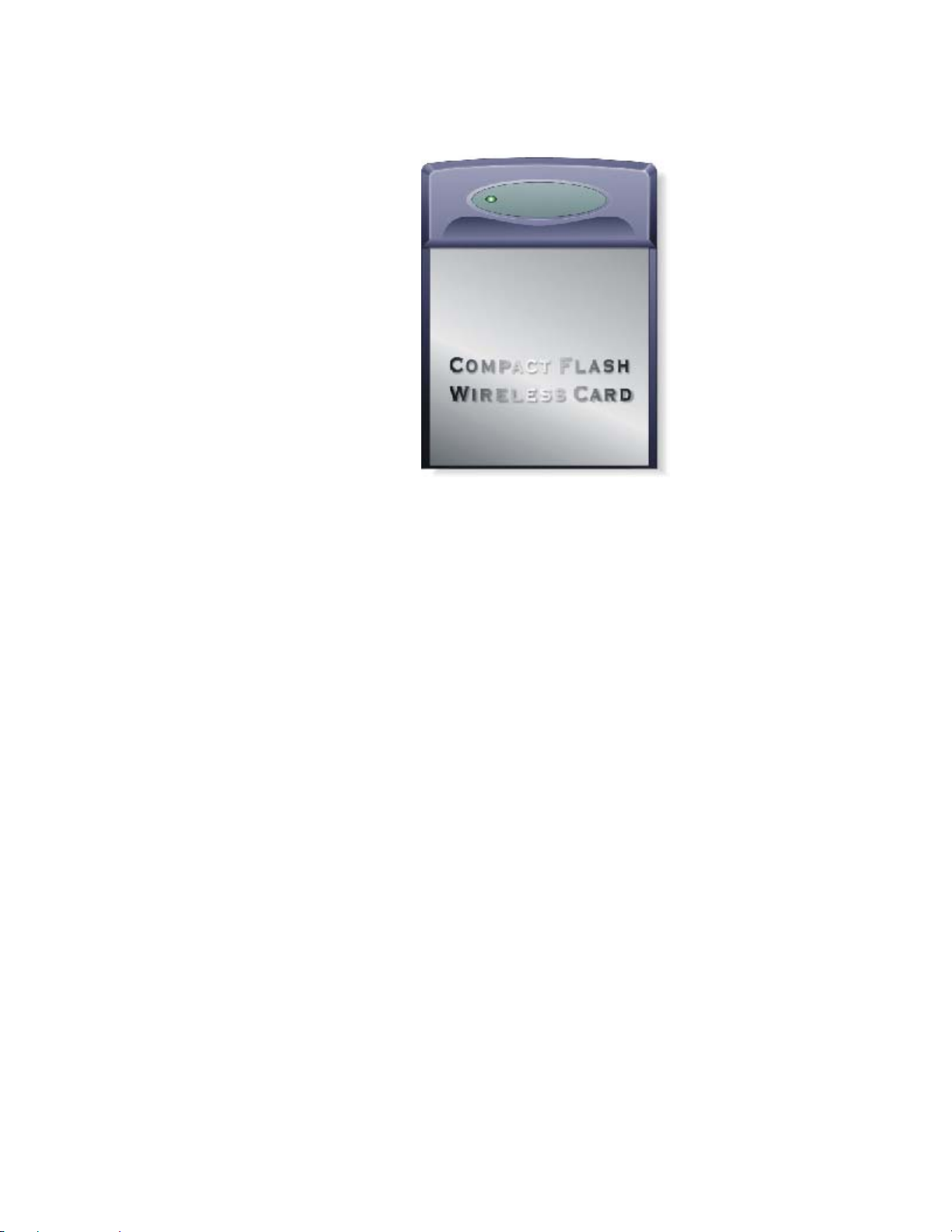
Figure 1
Page 7

2. Installing and Configuring the Wireless Network for
Pocket PC
2.1 Preparation
Before beginning the installation, prepare the following hardware and
software:
• A USI 802.11b WLAN CF Card
• A Software and Documentation CDROM for USI 802.11b WLAN
CF Card
• A Pocket PC(or Handhelp PC) with CF Type I and Type II
extended card slots
• A Sync cable
• A Desktop computer with a CDROM drive
2.2 Installing the Driver and Utility from a CDROM
To download the driver and utility from the Software and Documentation
CDROM to a Pocket PC in a Windows CE 3.0 or 4.0 environment:
[NOTE]: Refer to the documentation shipped with the Microsoft ActiveSync
program to ensure the desktop computer used in the driver installation meets the
system requirements for the ActiveSync program.
1. Connect the sync cable to a serial or USB port between the desktop
computer and the Pocket PC.
Once a connection exists between the desktop computer and the
Pocket PC, file transfers and data synchronization can take place.
2. Insert the Software and Documentation CDROM into the CDROM
drive on the desktop PC.
3. Run the setup program(setup.exe) from the folder
CD:\Win_CE\CE300 or CD:\Win_CE\CE400
Follow the sequential setup-instructions on Desktop PC screen to
finish installation.
4. Insert the USI 802.11b WLAN CF Card into the CF slot.
Page 8
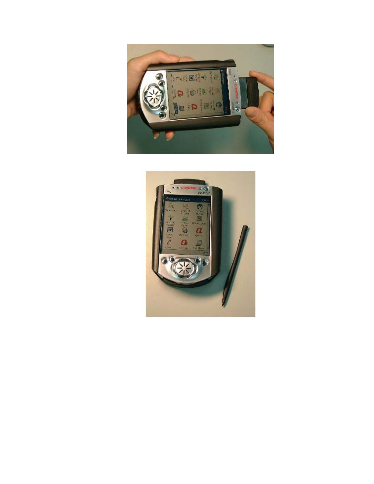
Figure 2
The Client Manager utility(See chapter 4) will be executed and
hidden on the task bar of the Today screen
Page 9

.
Figure 3
2.3 Configuring the Wireless Network in Windows CE
To configure the Wireless Network in a Windows CE environment.
1. Insert the USI 802.11b WLAN CF Card into a CF slot of the Pocket
PC.
2. Click the “USI WLAN Settings(CF)” icon to run the Wireless
Networking Setting utility from StartÆSettingsÆSystem
Page 10

Figure 4
You can:
¾ (I) Select a profile and click the “OK” button to switch your station
from one wireless network to another
¾ (II) Click “Add” or “Edit” button to add or edit the selected profile.
¾ (III) Click “Delete” button to delete the selected profile
Page 11

(I) “Select a Profile”
You can select a configuration profile to switch your station from
one wireless network to another.
[NOTE]:Before you can start using Configuration Profiles, you have to
add a Configuration Profile for each wireless network environment that
you want to participate in with your (mobile) Wireless Client Station. If
you plan to use your Wireless Client Station in multiple networking
environments that require different configuration settings, you can define
dedicated profiles for each environment. For example you can create a
Configuration Profile for:
your office head quarters
•
a branch-office
•
your home or SOHO network
•
After creating configuration profiles, you can easily switch your station
from one wireless network to another by selecting one of the profiles.
(II) “Add/Edit” Configuration profile
¾ Assign a name to your wireless configuration profile and select
the Network Type to identify the type of wireless connection
for this profile.
Access Point
Residential Gateway
Peer-to-Peer Group
Page 12

Figure 5
Click “Next” button to setup the Network Name
¾ Setup the Network Name
Use this screen to identify the Network Name of the wireless
network to which you wish to connect your computer.
• When connecting to a Base Station, consult the LAN
Administrator of the network for the correct value, or use
the Scan button to retrieve a list of open wireless
networks
• When connecting to a Peer-to-Peer Group, consult one
of the workgroup participants for the correct value.
Valid value is a case-sensitive string of ASCII printable
characters with a maximum of 32 characters. The value ANY
will allow your computer to connect to the first open Base
Station network that it can find.
Page 13

Figure 6
Click “Back” button to go back the last setting screen
Click “Next” button to setup the encryption key.
¾ Security Settings
Use this screen to:
Enable or disable wireless data encryption
•
Enter the encryption key that applies in your network.
•
You can enter key values in either Alphanumeric Value or
Hexadecimal Value. The encryption key value is casesensitive. Consult your LAN Administrator for the correct
value.
Page 14

Figure 7
Click “Back” button to go back the last setting screen
Click “Next” button to enable/disable the power saving
¾ Card Power Management
Use this screen to:
Enable Power Management for low power
•
consumption and wireless performance.
Disable Power Management for default power
•
consumption and high wireless performance (default).
Page 15

Figure 8
Click “Back” button to go back the last setting screen
Click “Finish” button to finish the setting job
Page 16

3. Using the Client Manager Utility
3.1 Installing the Client Manager
The Client Manager utility comes bundled with the USI 802.11b WLAN CF
Card driver on the Software and Documentation CDROM.
Once you complete the driver installation instructions described in Chapter
3 and insert the card into Pocket PC, the Client Manager utility will be
executed and hidden on the task bar of the Today screen.
You can use the Client Manager to do “link test” and “site survey”. The
Client Manager task tray icon conveys real-time signal strength and
connection status. The Client Manager also displays the driver and
firmware revision data. Alternatively, you can configure the USI 802.11b
WLAN CF Card by clicking the tray icon on the task bar.
3.2 The meaning of Tack Tray Icons
ICON Status
Excellent connection
Good connection
Marginal connection
Poor connection
No connection
No quality info availablw(no driver,
incompatible driver, etc)
3.3 Using the Client Manager
Click the tray icon to enter the Client Manager screen and see the wireless
network status.
Page 17

You can use the “Tools” pop-up menu to
• enter the Configuration profile edit screen
• see the driver and firmware revision
• enable/disable the settings “suspend while connected” and
“Load/Unload automatically”
• suppress the Client Manager(hidden on the task bar)
Figure 9
Figure 10
Page 18

You can use the “Advanced” pop-up menu to
• scan the Access points in range and monitor them
• select a partner to do link-testing
Figure 11
Page 19

4. Card Specifications
4.1 Physical Specifications
Form Factor
Dimensions
Temperature & Humidity
Operation
Storage
0° to 60° C
-10° to 70° C
4.2 Power Characteristics
Doze Mode
Receive Mode
Transmit Mode
Power supply
4.3 Networking Characteristics
Compatibility
Network Operating
System
Host Operating
System
Media Access
Protocol
Data Rate
• IEEE 802.11 Standard for Wireless LANS
(DSSS)
• Wi-Fi (Wireless Fidelity) certified by the
Wireless Ethernet Compatibility Alliance
(WECA).
Microsoft Windows Networking
Windows CE 3.0 & 4.0
CSMA/CA(Collision Avoidance) with
Acknowledgment(ACK)
• High
• Medium
• Standard
• Low
The card use an automatic Transmit Rate Select
mechanism
CF Card Type I Extended
52.5x42.8x5 mm
Maximum humidity 95%
10 to 90%(no condensation)
10 mA
180 mA
280 mA
3.3 V
11 Mb/s
5.5 Mb/s
2 Mb/s
1 Mb/s
Page 20

4.4 Radio Characteristics
Radio Characteristics of USI 802.11b WLAN CF Cards may vary:
• According to the country where the product was purchased.
• According to the type of product that was purchased.
Wireless communication is often subject to local radio regulations. Although
“USI 802.11b WLAN CF Card” wireless networking products have been designed
for operation in the license-free 2.4 GHz band, local radio regulations may
impose a
number of limitations to the use of wireless communication equipment.
To comply with such regulations, USI 802.11b WLAN CF Cards are marketed
with dedicated channel-sets with a number of factory-programmed channels
identified by the following acronyms:
• ETS for countries that adhere to the regulations as defined by the
European Telecommunications Standards Institute (ETSI).
• FCC for countries that adhere to the regulations as defined by the US
Federal Communications Commission (FCC).
• FR for France, and
• JP for Japan.
The acronym of the channel-set supported by your card is printed on a label
on the back-side of your USI 802.11b WLAN CF Card.
Radio Characteristics USI 802.11b WLAN CF Card
A
R-F Frequency Band 2.4 GHz (2400-2500 MHz)
North America (FCC) 11
Number of selectable
sub-channels
Europe (ETS) 13
France (FR) 4
Japan (JP) 1
Other Countries: FCC 11, ETS 13
Direct Sequence Spread Spectrum
Modulation Technique
CCK for High & Medium Transmit Rate
DQPSK for Standard Transmit Rate
•
DBPSK for Low Transmit Rate
Spreading 11-chip Barker Sequence
Bit Error Rate (BER) Better than 10
-5
Nominal Output Power 15 dBm
Page 21

Range (100 bytes User
Data) / Transmit Rate
Open Office Environment
Semi-Open Office
Environment
Closed Office
Receiver Sensitivity -83 dBm -87 dBm -91 dBm -94 dBm
Delay Spread
(at FER of <1%)
[Note]:
• In Open Office environments, antennas can “see” each other, i.e. there
are no physical obstructions between them.
• In Semi-open Office environments, work space is divided by shoulder-
height, hollow wall elements; antennas are at desktop level.
In Closed Office environments, work space is separated by floor-to-ceiling brick
walls.
High
Speed
11 Mb/s
160 m
(525 ft.)
50 m
(165 ft.)
25 m
(80 ft.)
65 ns 225 ns 400 ns 500 ns
Medium
Speed
5.5 Mb/s
270 m
(885 ft.)
70 m
(230 ft.)
35 m
(115 ft.)
Standard
Speed
2 Mb/s
400 m
(1300 ft.)
90 m
(300 ft.)
40 m
(130 ft.)
Low
Speed
1 Mb/s
550 m
(1750 ft.)
115 m
(375 ft.)
50 m
(165 ft.)
CAUTION: To maintain compliance with FCC’s RF exposure guidelines, this equipment
should be installed and operated with minimum distance 20cm between the radiator and
your body. Use on the supplied antenna. Unauthorized antenna, modification, or
attachments could damage the transmitter and may violate FCC regulations.
This device complies with Part 15 of the FCC Rules. Operation is subject to the following
two conditions:
(1) This device may not cause harmful interference.
(2) This device must accept any interference received, including interference that may
cause undesired operation.
Page 22

Basic Troubleshooting
If you cannot connect your USI 802.11b WLAN CF Card to the network, the
first troubleshooting hint is to verify LED activity of the CF Card . The LEDs
may show the following behavior:
Power LED on, Transmit/Receive LED off
•
Power LED on, Transmit/Receive LED flickering
•
Both LEDs blink once every 10 seconds
•
Power LED is Flickering
•
No LED Activity
•
If there is LED activity, run the Client Manager diagnostic tool on your station
to:
Run the Link Test to verify the quality of wireless network interface
•
radio communications with the network.
Power LED on, Transmit/Receive LED off
This LED status indicates normal operation:
The USI 802.11b CF WLAN Card is powered on
•
The Transmit/Receive LED indicates there is no activity on the wireless
•
network.
The absence of activity on the Wireless Network Interface might be related to
he fact that:
You moved out of Wireless Range of the Base Station(s) that could
•
provide access to the selected network.
There are no Wireless Client Stations in the Wireless Range of your
•
computer to participate in the selected Peer-to-Peer Group.
The Base Station(s) that could provide access to the selected network has
•
(have) a problem (e.g. power is off).
Power LED on, Transmit/Receive LED flickering
This LED status indicates normal operation:
The USI 802.11b WLAN CF Card is powered on
•
The Transmit/Receive LED indicates activity on the wireless network.
•
Page 23

If the radio of your USI 802.11b WLAN CF Card seems to communicate with
other radio devices, but does not succeed in actually connecting to the
network (i.e. the power and radio LED shows normal activity), you may need
to verify whether your operating system installed the correct Network Protocol
Settings.
Both LEDs blink once every 10 seconds
This LED indicates that the USI 802.11b WLAN CF Card is powered on
and working properly, but it is not able to establish a wireless connection
to the wireless network.
Possible causes might be:
Your wireless station is outside the Wireless Range of the Base
•
Station(s) that could provide you access to the selected network.
The Wireless Network Interface of your station has been configured
•
with an incorrect Network Name and/or Encryption Key settings.
By mistake you selected a configuration profile on your wireless
•
station, that does not belong to the wireless network that you want
to connect to.
The Base Station(s) that could provide access to the selected
•
network has (have) been configured to deny access to stations that
use the value ANY as their Network Name.
Contact your LAN Administrator for information about the correct values of
the parameter settings that apply in your network.
No LED Activity
If there is absolutely no LED activity on the Power LED and
Receive/Transmit LED of the USI 802.11b WLAN CF Card, this may be
due to one of the following reasons:
The USI 802.11b WLAN CF Card device is not properly connected
•
to your computer.
No driver was installed to allow communication between your
•
computer and the wireless network interface.
Power LED is Flickering
A flickering Power LED identifies that you enabled the Card Power
Management option for the USI 802.11b WLAN CF Card of a Wireless
Client Station (Advanced Settings).
Page 24

Technical Support
The identification of the product :
Product Name : USI RoamUniversal 802.11b WLAN CF Card
Model Name : CF114100
Application : Handheld devices
Technical Contact :
Universal Scientific Industrial Co., Ltd. ( Headquarters )
Address : 135, Lane 351, Taiping Rd., Sec. 1, Tsao Tuen, Nan Tou,
Taiwan
USI Taipei Office : 10F, 420, Keelung Road, Sec. 1, Taipei, Taiwan
Contact Person : Ray Huang
Telephone : +886-2-2345-5006, Ext.119
Fax : +886-2-2345-5191
Email : rayhwang@ms.usi.com.tw
Technical Contact in the US :
Address : 685A Jarvis Drive, Morgan Hill, CA 95037, USA
Telephone : +1-408-776-1966
Fax : +1-408-778-5509
Website : www.usi.com.tw
 Loading...