

Page 1
Data Sheet
March
2006 Rev
1.0
(BM-GP
-
CS
-08A)
Features
Bluetooth 2.0+EDR USB module
Introduction
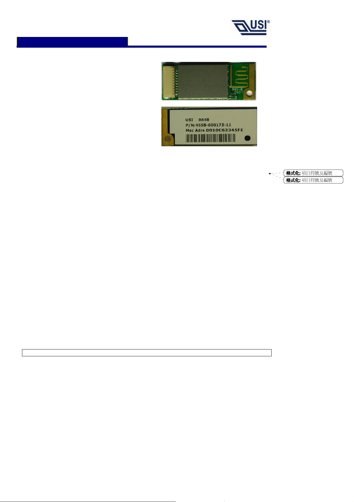
The Bluetooth Class 2 Module (model number
BM-GP-CS-08A) is a small module with 10way connector that provides a complete
2.4GHz Bluetooth system. This ready-to-use
Class2 Bluetooth module provides a fully
compliant Bluetooth system V2.0+EDR for
data and audio communications.
This module also provides the coexistence
solution that is critical for Notebook
implementation. The coexistence solution
includes AFH, and Activity Signaling (CSR
coexistence solution), WCS (Wireless
Coexistence Solution). AFH and Activity
Signaling is the default setting.
This module is provided with Toshiba PC stack
for Windows XP.
The module is ideally for Notebook PC, Table
PC and UMPC.
Fully Qualified Bluetooth v2.0 system
Enhanced Data Rate(EDR) compliant
for both 2Mbps & 3Mbps modulation
modes
With small size suitable for compact
system integration. Low power
consumption, extend the battery life.
Support for 802.11b/g Coexistence
including Intel WCS (Wireless
Coexistence System) (Optional).
Integrated Printed Antenna
On board 8 Mbits flash memory for
firmware upgrade
www.usi.com.tw
格格格格式化
式化::::
項目符號及編號
式化式化
格格格格式化
式化::::
項目符號及編號
式化式化
All rights are reserved by USI. No part of this technical document can be reproduced in any form without permission of USI.
Page 2

(Only available
Activity Signalling. Or
(Only available when WCS is
. (Not available when WCS is
Bluetooth USB Module (BM-GP-CS-08A)
General Description
Features Description
Standards
Frequency Band
Sensitivity
Output Power
Integrated Antenna
Coverage
Temperature
Operating Voltage
Power Consumption
Data Rate
Interface
Dimensions
Weight
Fully compliant with Bluetooth
2.402GHz ~ 2.480GHz
-82 dBm
4 dBm max with power control (Maximum Power measurement is from
chip set)
Type A: Average gain: -2.95dbi @2.45GHz (max)
Type B: Average gain: -4.4dbi @2.45GHz (max)
10m ~20m (Varies depending on operating environment)
Operating temperature: 0 °C to +70 °C
Storage temperature: -40 °C to +85 °C
3.3V DC +/- 10%
Peak RF current during TX burst: 65 mA
Peak RF current during RX burst: 47 mA
Asynchronous:723.2kbps/57.6kbps
Synchronous:433.9kbps/433.9kbps
JST SM10B-SRSS-TB connector
Length: 36.0 mm, Width: 13.8 mm, Height: 3.8 mm
2.0 grams +/- 15%
Electrical Connector Pinout
TM
2.0+EDR Standard
Figure 1: Connector pin assignment
Pin Number
1
2
3
4
5
6
7
8
9
10
GND
USB_D+
USB_D-
BT_Active
BT_Priority / Ch_Clk
HW_RADIO_DIS# (Optional) Disable radio transmissions when low
WLAN_Active / Ch_Data
+3.3V
LED
GND
Pin Name
Ground
USB D+
USB D-
BT_Active output to WLAN for Co-Existence.
BT Priority and Channel Clock for WCS.
when WCS is enabled.)
Description
WLAN_Active input from WLAN for
Channel Data for W CS
enabled).
3.3V power input
LED indicator for radio activity
enabled)
Ground
Table 2: Connector pin assignment
All rights are reserved by USI. No part of this technical document can be reproduced in any form without permission of USI.
1
Page 3
Bluetooth USB Module (BM-GP-CS-08A)
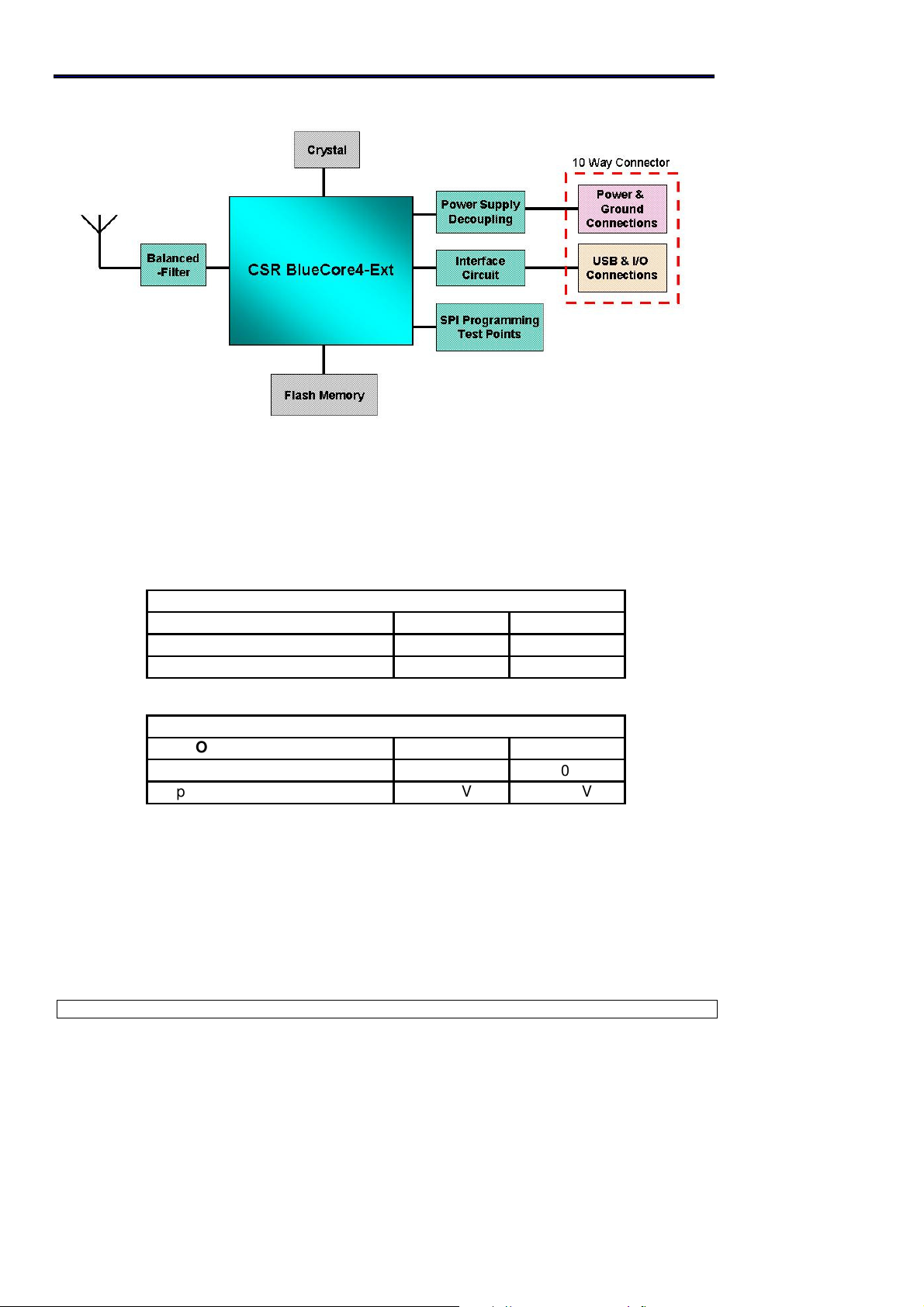
Block Diagram
Figure 2: Module Block Diagram
Electrical Characteristics
Absolute Maximum Ratings
Rating Min Max
Storage Temperature
Supply Voltage: VDD -0.40V +3.60V
Recommended Operating Conditions
Operating Condition Min Max
Operating Temperature Range*
Supply Voltage: VDD
-40 °C +85 °C
0 °C
+3.0V
+70 °C
+3.60V
All rights are reserved by USI. No part of this technical document can be reproduced in any form without permission of USI.
2
Page 4
= 4.0mA),
4.0mA),
Output levels to correctly terminated USB
Bluetooth USB Module (BM-GP-CS-08A)
Input/Output Terminal Characteristics
Digital Terminals
Input Voltage
VIL input logic level low (VDD=3.0V) -0.4 +0.8 V
VIH input logic level high 0.7VDD
Output Voltage
VOL output logic level low, (l
O
VDD=3.0V
VOH output logic level high, (lO = VDD=3.0V
USB Terminals
Input threshold
VIL input logic level low - - 0.3VDD V
VIH input logic level high 0.7VDD
Input leakage current
VSS < VIN< VDD -1 1 5 µA
CI Input capacitance 2.5 - 10 pF
Cable
VOL output logic level low 0 - 0.2 V
VOH output logic level high 2.8 - VDD V
Min Typ Max Unit
- VDD+0.4 V
- - 0.2 V
VDD-0.2
- - V
Min Typ Max Unit
- - V
Average Current Consumption
VDD=3.3V Temperature = 20°C
Mode Typ Unit
ACL data transfer 1Mbps USB (Slave) 50 mA
ACL data transfer 1Mbps USB (Master) 58 mA
Standby Mode (Connected to host, no RF activity) 10 mA
Deep Sleep 380 uA
Peak Current Consumption
VDD=3.3V Temperature = 20°C
Mode Typ Unit
Peak RF current during TX burst (+4 dBm , CW mode) 55.0 mA
Peak RF current during TX burst (0 dBm , CW mode) 52.0 mA
Peak RF current during RX burst (-82 dBm) 44.0 mA
All rights are reserved by USI. No part of this technical document can be reproduced in any form without permission of USI.
3
Page 5

Bluetooth USB Module (BM-GP-CS-08A)
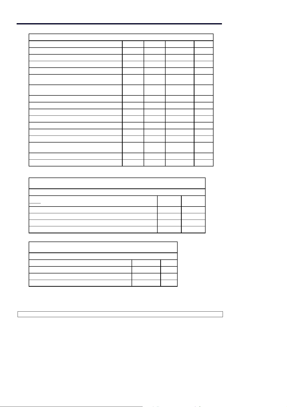
Radio Characteristics
Radio Characteristics, VDD = 3.3V Temperature = +20°C
Frequency
(GHz)
2.402 - -82 -78
2.441 - -84 -80
2.480 - -84 -80
2.402 0 - -
2.441 0 - -
2.480 0 - -
Frequency
(GHz)
2.402 -3 4 -
2.441 -3 4 -
2.480 -3 4 -
2.402 - 10 35
2.441 - 10 35
2.480 - 10 35
Frequency
(GHz)
2.402 140 165 175
2.441 140 165 175
2.480 140 165 175
2.402 115 140 -
2.441 115 140 -
2.480 115 140 -
Receiver
Sensitivity at 0.1% BER
Maximum received signal at 0.1% BER
Transmitter
RF transmit power
Initial carrier frequency tolerance
RF power control range
20dB bandwidth for modulated carrier
Drift ( five slot packet)
Drift Rate
∆f1avg “Maximum Modulation”
∆f2max “Minimum Modulation”
Notes:
Results shown are referenced to input of the RF Balanced-Filter.
Min Typ Max
Min Typ Max
25 35 - ≥16
-
-
-
Min Typ Max
Bluetooth
Specification
≤−70
≥-20
Bluetooth
Specification
-6 to +4
75
820 1000 ≤1000
±15
±25
±250
±400
±25
±400
Bluetooth
Specification
140≤f1avg≤175
≥115
Unit
dBm
dBm
dBm
dBm
dBm
dBm
Unit
(4)
dBm
dBm
dBm
kHz
kHz
kHz
kHz
kHz
Hz/µs
Unit
kHz
kHz
kHz
kHz
kHz
kHz
dB
All rights are reserved by USI. No part of this technical document can be reproduced in any form without permission of USI.
4
Page 6

Bluetooth USB Module (BM-GP-CS-08A)
Radio Characteristics, C/I and Adjacent Channel Power
VDD = 3.3V Temperature = +20°C Frequency = 2441 MHz
Receiver
C/I co-channel - 9 11 ≤11
Adjacent channel selectivity C/I F=F0+1MHz - -4 0 ≤0 dB
Adjacent channel selectivity C/I F=F0-1MHz - -4 0 ≤0 dB
Adjacent channel selectivity C/I F=F0+2MHz - -35 -30 ≤-30 dB
Adjacent channel selectivity C/I F=F0-2MHz - -21 -20 ≤-20 dB
Adjacent channel selectivity C/I F=F0+3MHz - -45 -40 ≤-40 dB
Adjacent channel selectivity C/I F=F
Adjacent channel selectivity C/I F=F0-4MHz - -25 -20 ≤-20 dB
Image
Transmitter
Adjacent channel transmit power F=F0±2MHz - -35 -20 ≤-20 dBm
Adjacent channel transmit power F=F0±3MHz - -45 -40 ≤-40 dBm
Min Typ Max
- -18 -9 ≤-9 dB
Min Typ Max
Bluetooth
Specification
Bluetooth
Specification
Unit
dB
Unit
All rights are reserved by USI. No part of this technical document can be reproduced in any form without permission of USI.
5
Page 7

Bluetooth USB Module (BM-GP-CS-08A)
Mounting Guide for Antenna Radiation
In order to achieve longest communication range, please keep the area surrounding antenna free of grounding
or metal housing.
All rights are reserved by USI. No part of this technical document can be reproduced in any form without permission of USI.
6
Page 8

Bluetooth USB Module (BM-GP-CS-08A)
Impedance Matching of Antenna
BM-GP-CS-08/A/B utilizes a meander line printed antenna for radiate communication.
Application environments, such as notebooks, PDAs, headsets or other handheld devices,
both have plastic housings, different motherboards and other mechanism structures. These
factors will cause the deviation of antenna resonant frequency. Therefore, impedance
matching of antenna should be optimized for various applications to achieve longest
communication range. Please consult USI for further information.
All rights are reserved by USI. No part of this technical document can be reproduced in any form without permission of USI.
7
Page 9

Bluetooth USB Module (BM-GP-CS-08A)
Mechanical Drawing
All rights are reserved by USI. No part of this technical document can be reproduced in any form without permission of USI.
8
Page 10

NOTE: THE MANUFACTURER IS NOT RESPONSIBLE FOR ANY RADIO OR TV
INTERFERENCE CAUSED BY UNAUTHORIZED MODIFICATIONS TO THIS
EQUIPMENT. SUCH MODIFICATIONS COULD VOID THE USER’S AUTHORITY TO
OPERATE THE EQUIPMENT.
Bluetooth USB Module (BM-GP-CS-08A)
Label Information
First line: USI and Date code. The first two digits of date code is the year and last two digits
are the week number. The date code is used to identify the production date.
Second line: The part numer which may have different information.
Third line: The MAC address.
WARNING:
THIS DEVICE COMPLIES WITH PART 15 OF THE FCC RULES. OPERATION IS SUBJECT
TO THE FOLLOWING TWO CONDITIONS:
(1) THIS DEVICE MAY NOT CAUSE HARMFUL INTERFERENCE, AND
(2) THIS DEVICE MUST ACCEPT ANY INTERFERENCE RECEIVED, INCLUDING
INTERFERENCE THAT MAY CAUSE UNDESIRED OPERATION.
All rights are reserved by USI. No part of this technical document can be reproduced in any form without permission of USI.
9
Page 11

10
Bluetooth USB Module (BM-GP-CS-08A)
Packaging
For Additional information, please contact the following:
Universal Scientific Industrial Co., Ltd.
Headquarters
141, Lane 351, Taiping Road, Sec. 1, Tsao-Tuen , Taiwan,
Http://www.usi.com.tw
Tel: + 886-49-2350876, 2325876
Fax: +886-49-3439561, 2337360, 2351093
E-mail:usi@ms.usi.com.tw
All rights are reserved by USI. No part of this technical document can be reproduced in any form without permission of USI.
 Loading...