

Page 1

User Manual
UR3/CB3
Original instructions (en)
Page 2

Page 3

User Manual
UR3/CB3
Version 3.1 (rev. 17782)
Original instructions (en)
Serial number UR3:
Serial number CB3:
Page 4

The information contained herein is the property of Universal Robots A/S and shall not be repro-
duced in whole or in part without prior written approval of Universal Robots A/S. The informa-
tion herein is subject to change without notice and should not be construed as a commitment by
Universal Robots A/S. This manual is periodically reviewed and revised.
Universal Robots A/S assumes no responsibility for any errors or omissions in this document.
Copyright © 2009-2015 by Universal Robots A/S
The Universal Robots logo is a registered trademark of Universal Robots A/S.
Copyright © 2009-2015 by Universal Robots A/S. All rights reserved.
UR3/CB3 ii Version 3.1 (rev. 17782)
Page 5

Contents
Preface ix
What do the Boxes Contain . . . . . . . . . . . . . . . . . . . . . . . . ix
Important Safety Notice . . . . . . . . . . . . . . . . . . . . . . . . . x
How to Read This Manual . . . . . . . . . . . . . . . . . . . . . . . . x
Where to Find More Information . . . . . . . . . . . . . . . . . . . . . . x
I Hardware Installation Manual I-1
1 Safety I-3
1.1 Introduction . . . . . . . . . . . . . . . . . . . . . . . . . . . I-3
1.2 Validity and Responsibility . . . . . . . . . . . . . . . . . . . . . . I-3
1.3 Limitation of Liability. . . . . . . . . . . . . . . . . . . . . . . . I-4
1.4 Warning Symbols in this Manual . . . . . . . . . . . . . . . . . . . . I-4
1.5 General Warnings and Cautions . . . . . . . . . . . . . . . . . . . . I-5
1.6 Intended Use . . . . . . . . . . . . . . . . . . . . . . . . . . . I-7
1.7 Risk Assessment. . . . . . . . . . . . . . . . . . . . . . . . . . I-7
1.8 Emergency Stop . . . . . . . . . . . . . . . . . . . . . . . . . . I-8
1.9 Movement Without Drive Power. . . . . . . . . . . . . . . . . . . . I-8
2 Transportation I-11
3 Mechanical Interface I-13
3.1 Workspace of the Robot . . . . . . . . . . . . . . . . . . . . . . . I-13
3.2 Mounting . . . . . . . . . . . . . . . . . . . . . . . . . . . . I-13
4 Electrical Interface I-19
4.1 Introduction . . . . . . . . . . . . . . . . . . . . . . . . . . . I-19
4.2 Electrical warnings and cautions . . . . . . . . . . . . . . . . . . . . I-19
4.3 Controller I/O . . . . . . . . . . . . . . . . . . . . . . . . . . I-21
4.3.1 Common specifications for all digital I/O . . . . . . . . . . . . . . I-21
4.3.2 Safety I/O . . . . . . . . . . . . . . . . . . . . . . . . . I-22
4.3.3 General purpose digital I/O. . . . . . . . . . . . . . . . . . . I-26
4.3.4 Digital input from a button . . . . . . . . . . . . . . . . . . . I-26
4.3.5 Communication with other machines or PLCs . . . . . . . . . . . . I-27
4.3.6 General purpose analog I/O. . . . . . . . . . . . . . . . . . . I-27
4.3.7 Remote ON/OFF control . . . . . . . . . . . . . . . . . . . . I-29
4.4 Tool I/O . . . . . . . . . . . . . . . . . . . . . . . . . . . . I-30
4.4.1 Tool Digital Outputs . . . . . . . . . . . . . . . . . . . . . I-31
4.4.2 Tool Digital Inputs . . . . . . . . . . . . . . . . . . . . . . I-32
4.4.3 Tool Analog Inputs . . . . . . . . . . . . . . . . . . . . . . I-32
Copyright © 2009-2015 by Universal Robots A/S. All rights reserved.
Version 3.1 (rev. 17782)
iii UR3/CB3
Page 6

4.5 Ethernet. . . . . . . . . . . . . . . . . . . . . . . . . . . . . I-33
4.6 Mains connection . . . . . . . . . . . . . . . . . . . . . . . . . I-34
4.7 Robot connection . . . . . . . . . . . . . . . . . . . . . . . . . I-35
5 Safety-related Functions and Interfaces I-37
5.1 Limiting Safety-related Functions . . . . . . . . . . . . . . . . . . . I-37
5.2 Safety Modes . . . . . . . . . . . . . . . . . . . . . . . . . . . I-39
5.3 Safety-related Electrical Interfaces . . . . . . . . . . . . . . . . . . . I-39
5.3.1 Safety-related Electrical Inputs . . . . . . . . . . . . . . . . . . I-39
5.3.2 Safety-related Electrical Outputs . . . . . . . . . . . . . . . . . I-41
6 Maintenance and Repair I-43
6.1 Safety Instructions . . . . . . . . . . . . . . . . . . . . . . . . . I-43
7 Disposal and Environment I-45
8 Certifications I-47
8.1 Third Party Certifications . . . . . . . . . . . . . . . . . . . . . . I-47
8.2 Declarations According to EU directives . . . . . . . . . . . . . . . . . I-47
9 Warranties I-49
9.1 Product Warranty . . . . . . . . . . . . . . . . . . . . . . . . . I-49
9.2 Disclaimer . . . . . . . . . . . . . . . . . . . . . . . . . . . . I-49
Copyright © 2009-2015 by Universal Robots A/S. All rights reserved.
A Stopping Time and Stopping Distance I-51
A.1 CATEGORY 0 stopping distances and times. . . . . . . . . . . . . . . . I-51
B Declarations and Certificates I-53
B.1 CE Declaration of Incorporation (original) . . . . . . . . . . . . . . . . I-53
B.2 Safety System Certificate. . . . . . . . . . . . . . . . . . . . . . . I-54
B.3 Environmental Test Certificate. . . . . . . . . . . . . . . . . . . . . I-55
B.4 EMC Test Certificate . . . . . . . . . . . . . . . . . . . . . . . . I-56
C Applied Standards I-57
D Technical Specifications I-63
II PolyScope Manual II-1
10 Introduction II-3
10.1 Getting Started . . . . . . . . . . . . . . . . . . . . . . . . . . II-3
10.1.1 Installing the Robot Arm and Control Box. . . . . . . . . . . . . . II-3
10.1.2 Turning the Control Box On and Off . . . . . . . . . . . . . . . . II-4
10.1.3 Turning the Robot Arm On and Off . . . . . . . . . . . . . . . . II-4
10.1.4 Quick Start . . . . . . . . . . . . . . . . . . . . . . . . . II-4
10.1.5 The First Program . . . . . . . . . . . . . . . . . . . . . . II-5
10.2 PolyScope Programming Interface . . . . . . . . . . . . . . . . . . . II-6
10.3 Welcome Screen . . . . . . . . . . . . . . . . . . . . . . . . . . II-8
10.4 Initialization Screen . . . . . . . . . . . . . . . . . . . . . . . . II-9
UR3/CB3 iv Version 3.1 (rev. 17782)
Page 7

11 On-screen Editors II-11
11.1 On-screen Keypad . . . . . . . . . . . . . . . . . . . . . . . . . II-11
11.2 On-screen Keyboard . . . . . . . . . . . . . . . . . . . . . . . . II-12
11.3 On-screen Expression Editor . . . . . . . . . . . . . . . . . . . . . II-12
11.4 Pose Editor Screen . . . . . . . . . . . . . . . . . . . . . . . . . II-13
12 Robot Control II-17
12.1 Move Tab . . . . . . . . . . . . . . . . . . . . . . . . . . . . II-17
12.1.1 Robot . . . . . . . . . . . . . . . . . . . . . . . . . . . II-17
12.1.2 Feature and Tool Position. . . . . . . . . . . . . . . . . . . . II-18
12.1.3 Move Tool . . . . . . . . . . . . . . . . . . . . . . . . . II-18
12.1.4 Move Joints . . . . . . . . . . . . . . . . . . . . . . . . . II-18
12.1.5 Freedrive . . . . . . . . . . . . . . . . . . . . . . . . . II-18
12.2 I/O Tab . . . . . . . . . . . . . . . . . . . . . . . . . . . . . II-19
12.3 MODBUS client I/O . . . . . . . . . . . . . . . . . . . . . . . . II-20
12.4 AutoMove Tab . . . . . . . . . . . . . . . . . . . . . . . . . . II-20
12.5 Installation → Load/Save . . . . . . . . . . . . . . . . . . . . . . II-22
12.6 Installation → TCP Configuration . . . . . . . . . . . . . . . . . . . II-23
12.6.1 Adding, modifying and removing TCPs . . . . . . . . . . . . . . II-23
12.6.2 The default and the active TCP . . . . . . . . . . . . . . . . . . II-23
12.6.3 Teaching TCP position . . . . . . . . . . . . . . . . . . . . . II-24
12.6.4 Teaching TCP orientation. . . . . . . . . . . . . . . . . . . . II-25
12.6.5 Payload . . . . . . . . . . . . . . . . . . . . . . . . . . II-25
12.6.6 Center of gravity . . . . . . . . . . . . . . . . . . . . . . . II-25
12.7 Installation → Mounting. . . . . . . . . . . . . . . . . . . . . . . II-26
12.8 Installation → I/O Setup . . . . . . . . . . . . . . . . . . . . . . II-27
12.9 Installation → Safety . . . . . . . . . . . . . . . . . . . . . . . . II-28
12.10 Installation → Variables . . . . . . . . . . . . . . . . . . . . . . . II-28
12.11 Installation → MODBUS client I/O Setup . . . . . . . . . . . . . . . . II-29
12.12 Installation → Features . . . . . . . . . . . . . . . . . . . . . . . II-32
12.13 Conveyor Tracking Setup . . . . . . . . . . . . . . . . . . . . . . II-35
12.14 Installation → Default Program . . . . . . . . . . . . . . . . . . . . II-36
12.14.1 Loading a Default Program . . . . . . . . . . . . . . . . . . . II-37
12.14.2 Starting a Default Program . . . . . . . . . . . . . . . . . . . II-37
12.14.3 Auto Initialization . . . . . . . . . . . . . . . . . . . . . . II-37
12.15 Log Tab . . . . . . . . . . . . . . . . . . . . . . . . . . . . . II-38
12.16 Load Screen . . . . . . . . . . . . . . . . . . . . . . . . . . . II-38
12.17 Run Tab. . . . . . . . . . . . . . . . . . . . . . . . . . . . . II-41
13 Programming II-43
13.1 New Program . . . . . . . . . . . . . . . . . . . . . . . . . . II-43
13.2 Program Tab . . . . . . . . . . . . . . . . . . . . . . . . . . . II-44
13.2.1 Program Tree . . . . . . . . . . . . . . . . . . . . . . . . II-44
13.2.2 Program Execution Indication . . . . . . . . . . . . . . . . . . II-45
13.2.3 Undo/Redo Buttons . . . . . . . . . . . . . . . . . . . . . II-45
13.2.4 Program Dashboard. . . . . . . . . . . . . . . . . . . . . . II-45
Version 3.1 (rev. 17782)
v UR3/CB3
Copyright © 2009-2015 by Universal Robots A/S. All rights reserved.
Page 8

13.3 Variables . . . . . . . . . . . . . . . . . . . . . . . . . . . . II-46
13.4 Command: Empty . . . . . . . . . . . . . . . . . . . . . . . . . II-47
13.5 Command: Move . . . . . . . . . . . . . . . . . . . . . . . . . II-48
13.6 Command: Fixed Waypoint . . . . . . . . . . . . . . . . . . . . . II-51
13.7 Command: Relative Waypoint. . . . . . . . . . . . . . . . . . . . . II-53
13.8 Command: Variable Waypoint . . . . . . . . . . . . . . . . . . . . II-54
13.9 Command: Wait. . . . . . . . . . . . . . . . . . . . . . . . . . II-55
13.10 Command: Set . . . . . . . . . . . . . . . . . . . . . . . . . . II-55
13.11 Command: Popup . . . . . . . . . . . . . . . . . . . . . . . . . II-56
13.12 Command: Halt . . . . . . . . . . . . . . . . . . . . . . . . . . II-57
13.13 Command: Comment . . . . . . . . . . . . . . . . . . . . . . . . II-57
13.14 Command: Folder . . . . . . . . . . . . . . . . . . . . . . . . . II-58
13.15 Command: Loop . . . . . . . . . . . . . . . . . . . . . . . . . II-58
13.16 Command: SubProgram . . . . . . . . . . . . . . . . . . . . . . . II-59
13.17 Command: Assignment . . . . . . . . . . . . . . . . . . . . . . . II-60
13.18 Command: If . . . . . . . . . . . . . . . . . . . . . . . . . . . II-61
13.19 Command: Script . . . . . . . . . . . . . . . . . . . . . . . . . II-62
13.20 Command: Event . . . . . . . . . . . . . . . . . . . . . . . . . II-63
13.21 Command: Thread . . . . . . . . . . . . . . . . . . . . . . . . . II-64
13.22 Command: Pattern . . . . . . . . . . . . . . . . . . . . . . . . . II-64
13.23 Command: Force . . . . . . . . . . . . . . . . . . . . . . . . . II-66
13.24 Command: Pallet . . . . . . . . . . . . . . . . . . . . . . . . . II-69
13.25 Command: Seek . . . . . . . . . . . . . . . . . . . . . . . . . . II-70
13.26 Command: Start/Stop Conveyor Tracking . . . . . . . . . . . . . . . . II-73
13.27 Command: Suppress . . . . . . . . . . . . . . . . . . . . . . . . II-74
13.28 Graphics Tab . . . . . . . . . . . . . . . . . . . . . . . . . . . II-74
13.29 Structure Tab . . . . . . . . . . . . . . . . . . . . . . . . . . . II-75
13.30 Variables Tab . . . . . . . . . . . . . . . . . . . . . . . . . . . II-76
13.31 Command: Variables Initialization . . . . . . . . . . . . . . . . . . . II-77
Copyright © 2009-2015 by Universal Robots A/S. All rights reserved.
14 Setup Screen II-79
14.1 Language and Units . . . . . . . . . . . . . . . . . . . . . . . . II-80
14.2 Update Robot. . . . . . . . . . . . . . . . . . . . . . . . . . . II-81
14.3 Set Password . . . . . . . . . . . . . . . . . . . . . . . . . . . II-82
14.4 Calibrate Screen . . . . . . . . . . . . . . . . . . . . . . . . . . II-83
14.5 Setup Network . . . . . . . . . . . . . . . . . . . . . . . . . . II-83
14.6 Set Time. . . . . . . . . . . . . . . . . . . . . . . . . . . . . II-84
15 Safety Configuration II-85
15.1 Changing the Safety Configuration . . . . . . . . . . . . . . . . . . . II-86
15.2 Safety Synchronization and Errors . . . . . . . . . . . . . . . . . . . II-86
15.3 Tolerances . . . . . . . . . . . . . . . . . . . . . . . . . . . . II-87
15.4 Safety Checksum . . . . . . . . . . . . . . . . . . . . . . . . . II-88
15.5 Safety Modes . . . . . . . . . . . . . . . . . . . . . . . . . . . II-88
15.6 Freedrive Mode . . . . . . . . . . . . . . . . . . . . . . . . . . II-89
15.7 Password Lock . . . . . . . . . . . . . . . . . . . . . . . . . . II-89
15.8 Apply . . . . . . . . . . . . . . . . . . . . . . . . . . . . . II-89
UR3/CB3 vi Version 3.1 (rev. 17782)
Page 9

15.9 General Limits . . . . . . . . . . . . . . . . . . . . . . . . . . II-90
15.10 Joint Limits . . . . . . . . . . . . . . . . . . . . . . . . . . . II-93
15.11 Boundaries. . . . . . . . . . . . . . . . . . . . . . . . . . . . II-94
15.11.1 Selecting a boundary to configure. . . . . . . . . . . . . . . . . II-95
15.11.2 3D visualization . . . . . . . . . . . . . . . . . . . . . . . II-95
15.11.3 Safety plane configuration . . . . . . . . . . . . . . . . . . . II-96
15.11.4 Tool Boundary configuration . . . . . . . . . . . . . . . . . . II-99
15.12 Safety I/O . . . . . . . . . . . . . . . . . . . . . . . . . . . . II-101
Glossary II-103
Index II-105
Version 3.1 (rev. 17782)
Copyright © 2009-2015 by Universal Robots A/S. All rights reserved.
vii UR3/CB3
Page 10

Copyright © 2009-2015 by Universal Robots A/S. All rights reserved.
UR3/CB3 viii Version 3.1 (rev. 17782)
Page 11
Preface
Congratulations on the purchase of your new Universal Robot, UR3.
The robot can be programmed to move a tool, and communicate with other ma-
chines using electrical signals. It is an arm composed of extruded aluminum tubes
and joints. Using our patented programming interface, PolyScope, it is easy to pro-
gram the robot to move the tool along a desired trajectory.
What do the Boxes Contain
When you order a complete robot, you receive two boxes. One contains the the
robot arm and the following items are included in the other one:
• Control box with teach pendant;
• Mounting bracket for the control box;
• Mounting bracket for the teach pendant;
• Key for opening the control box;
• Mains cable compatible with your region;
• Tool cable;
• Stylus pen with laser;
• UR production test certificate;
Copyright © 2009-2015 by Universal Robots A/S. All rights reserved.
Version 3.1 (rev. 17782)
• This manual.
ix UR3/CB3
Page 12

Important Safety Notice
The robot is partly completed machinery (see 8.2) and as such a risk assessment is
required for each installation of the robot. It is particularly important that all of the
safety instructions in chapter 1 are followed.
How to Read This Manual
This manual contains instructions for installing and using the robot. It consists of
the following parts:
Hardware Installation Manual: The mechanical and electrical installation of the robot.
PolyScope Manual: Programming of the robot.
This manual is intended for the integrator who is expected to have a basic level of
mechanical and electrical training. It is also helpful, though not necessary, to be
familiar with elementary concepts of programming. No special knowledge about
robots in general or Universal Robots in particular is required.
Where to Find More Information
Copyright © 2009-2015 by Universal Robots A/S. All rights reserved.
Where to Find More Information
The support website (http://support.universal- robots.com/), available
to all UR distributors, contains additional information, such as:
• Other language versions of this manual;
• PolyScope Manual updates after the PolyScope is upgraded to a new version.
• The Service Manual with instructions for troubleshooting, maintenance and re-
pair of the robot.
• The Script Manual for advanced users.
UR3/CB3 x Version 3.1 (rev. 17782)
Page 13

Part I
Hardware Installation Manual
Page 14

Page 15

1 Safety
1.1 Introduction
This chapter contains important safety information, which must be read and un-
derstood by the integrator of UR robots.
The first subsections in this chapter are more general and the later subsections con-
tain more specific engineering data relevant for setting up and programming the
robot.
It is essential that all assembly instructions and guidanceprovided in other chapters
and parts of this manual are observed and followed.
Special attention shall be paid to text associated with warning symbols. See Chap-
ter 5 for detailed descriptions of the safety-related functions and interfaces.
1.2 Validity and Responsibility
The information does not cover how to design, install and operate a complete robot
application, nor does it cover all peripheral equipment that can influence the safety
of the complete system. The complete system must be designed and installed in
accordance with the safety requirements set forth in the standards and regulations
of the country where the robot is installed.
The integrators of UR robots are responsible for ensuring that the applicable safety
laws and regulations in the country concerned are observed and that any significant
hazards in the complete robot application are eliminated.
This includes, but is not limited to:
• Making a risk assessment for the complete system;
• Interfacing other machines and additional safety devices if defined by the risk
assessment;
• Setting up the appropriate safety settings in the software;
• Ensuring that the user will not modify any safety measures;
• Validating that the total system is designed and installed correctly;
• Specifying instructions for use;
• Marking the robot installation with relevant signs and contact information of
the integrator;
• Collecting all documentation in a technical file.
Guidance on how to find and read applicable standards and laws is provided on
http://support.universal-robots.com/
Copyright © 2009-2015 by Universal Robots A/S. All rights reserved.
Version 3.1 (rev. 17782)
I-3 UR3/CB3
Page 16
1.3 Limitation of Liability
Any information given in this manual regarding safety must not be construed as
a warranty by UR that the industrial manipulator will not cause injury or damage
even if all safety instructions are complied with.
1.4 Warning Symbols in this Manual
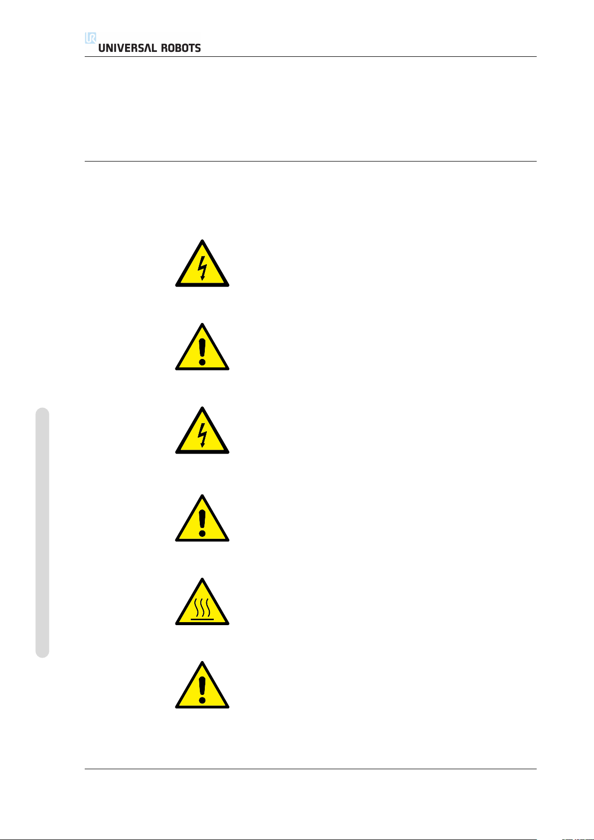
The table below defines the captions specifying the danger levels used throughout
this manual. The same warning signs are used on the product.
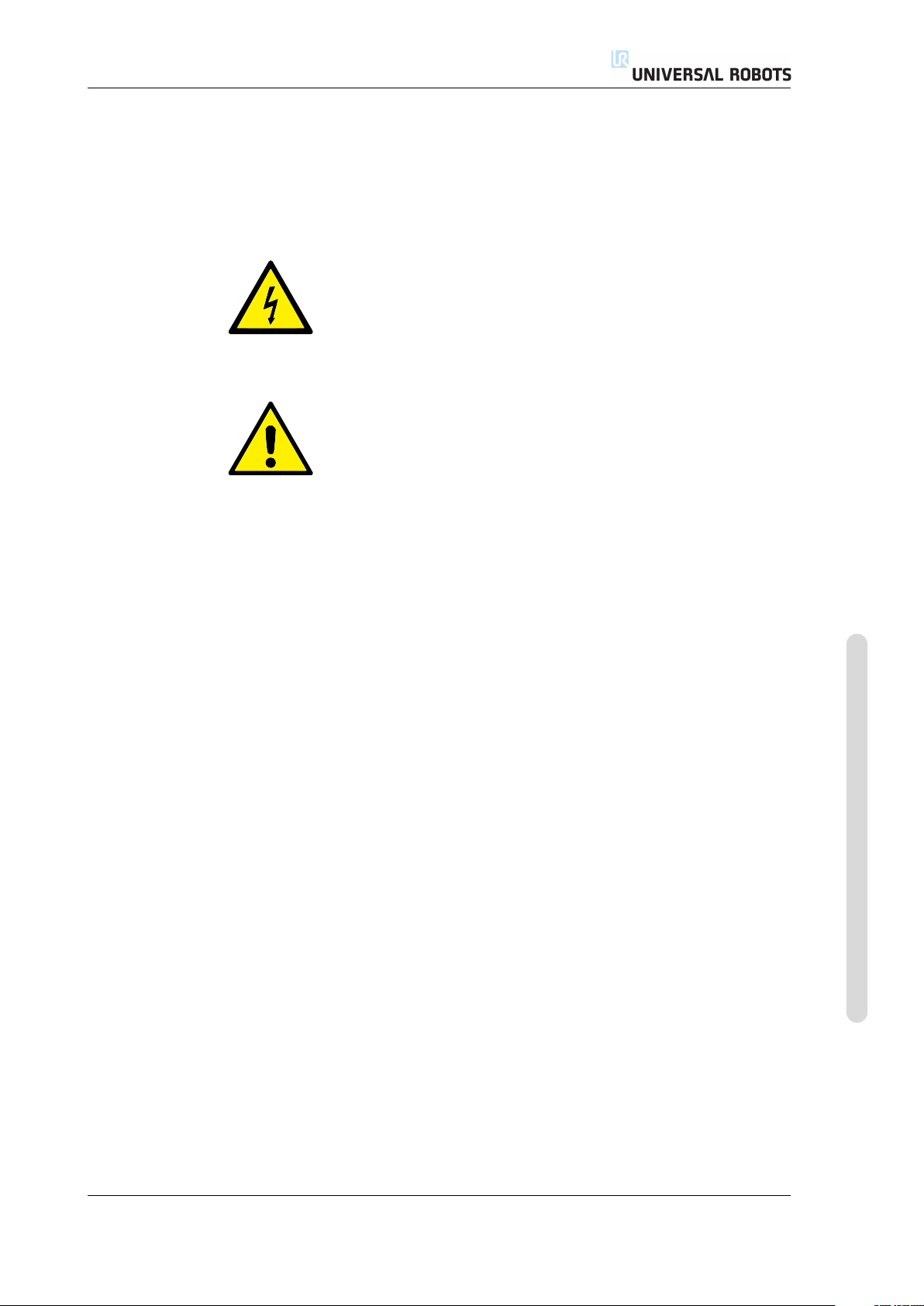
DANGER:
This indicates an imminently hazardous electrical situation which,
if not avoided, could result in death or serious injury.
DANGER:
This indicates an imminently hazardous situation which, if not
avoided, could result in death or serious injury.
1.4 Warning Symbols in this Manual
Copyright © 2009-2015 by Universal Robots A/S. All rights reserved.
WARNING:
This indicates a potentially hazardous electrical situation which, if
not avoided, could result in injury or major damage to the equip-
ment.
WARNING:
This indicates a potentially hazardous situation which, if not
avoided, could result in injury or major damage to the equipment.
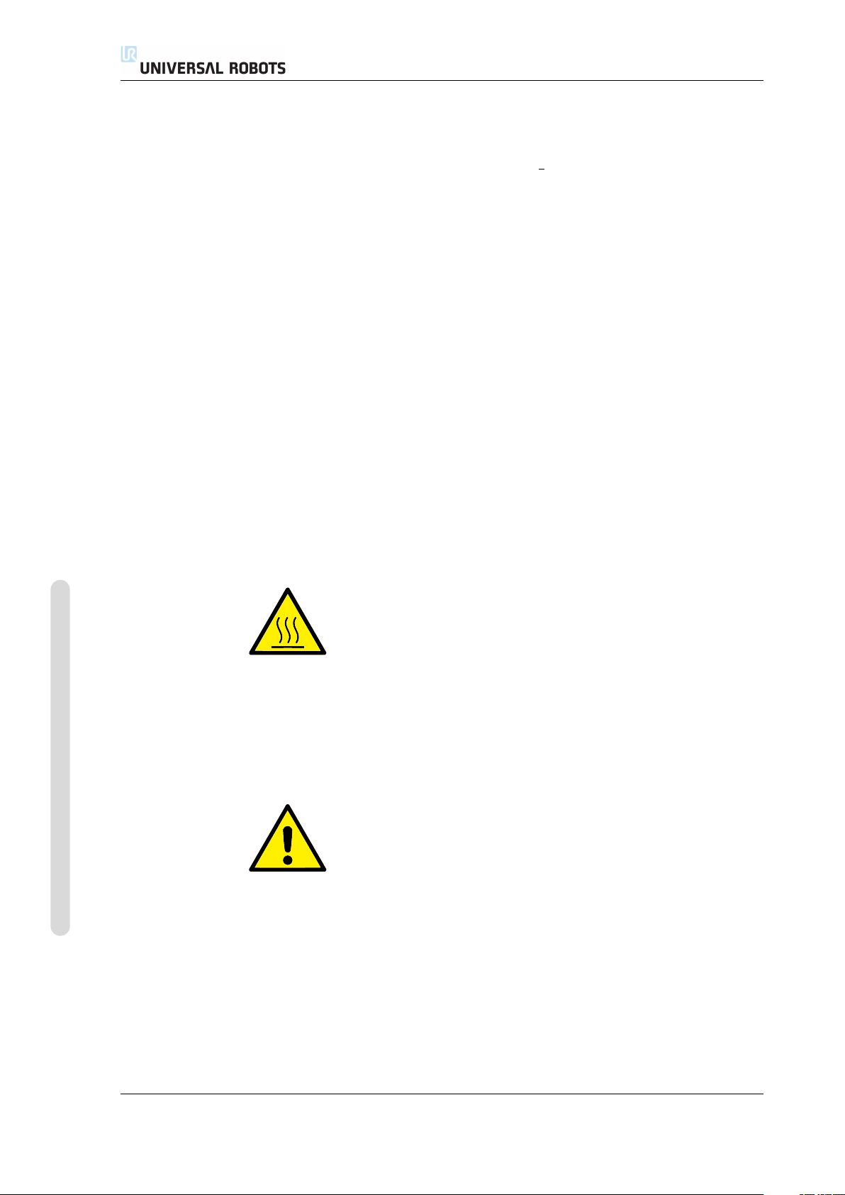
WARNING:
This indicates a potentially hazardous hot surface which, if
touched, could result in injury.
CAUTION:
This indicates a situation which, if not avoided, could result in
damage to the equipment.
UR3/CB3 I-4 Version 3.1 (rev. 17782)
Page 17
1.5 General Warnings and Cautions
1.5 General Warnings and Cautions
This section contains some general warnings and cautions. Some of which are re-
peated or explained in different parts of the manual. Other warnings and cautions
are present throughout the manual.
DANGER:
Make sure to install the robot and all electrical equipment accord-
ing to the specifications and warnings found in the Chapters 3 and
4.
WARNING:
1. Make sure the robot arm and tool are properly and securely
bolted in place.
2. Make sure the robot arm has ample space to operate freely.
3. Make sure that safety measures and/or robot safety configu-
ration parameters have been set up to protect both program-
mers, operators and bystanders, as defined in the risk assess-
ment.
4. Do not wear loose clothing or jewellery when working with
the robot. Make sure long hair is tied back when working
with the robot.
5. Never use the robot if it is damaged.
6. If the software prompts a fatal error, immediately activate
emergency stop, write down the conditions that led to the er-
ror, find the corresponding error codes on the log screen, and
contact your supplier.
7. Do not connect any safety equipment to normal I/O. Use
safety-related interfaces only.
8. Make sure to use the correct installation settings (e.g. Robot
mounting angle, weight in TCP, TCP offset, safety configura-
tion). Save and load the installations file along with the pro-
gram.
9. The freedrive function (Impedance/back-drive) shall only
be used in installations where the risk assessment allows
it. Tools and obstacles shall not have sharp edges or pinch
points. Make sure that all people keep their heads and faces
outside the reach of the robot.
Copyright © 2009-2015 by Universal Robots A/S. All rights reserved.
Version 3.1 (rev. 17782)
10. Be aware of robot movement when using the teach pendant.
11. Do not enter the safety range of the robot or touch the robot
when the system is in operation.
I-5 UR3/CB3
Page 18
1.5 General Warnings and Cautions
11. Collisions can release high portions of kinetic energy, which
are significantly higher at high speeds and with high pay-
loads. (Kinetic Energy =
1
Mass · Speed2)
2
12. Combining different machines might increase hazards or cre-
ate new hazards. Always make an overall risk assessment for
the complete installation. When different safety and emer-
gency stop performance levels are needed, always choose the
highest performance level. Always read and understand the
manuals for all equipment used in the installation.
13. Never modify the robot. A modification might create haz-
ards that are unforeseen by the integrator. All authorized
reassembling shall be done according to the newest version
of all relevant service manuals. UNIVERSAL ROBOTS DIS-
CLAIMS ANY LIABILITY IF THE PRODUCT IS CHANGED
OR MODIFIED IN ANY WAY.
14. If the robot is purchased with an extra module (e.g. eu-
romap67 interface) then look up that module in the respective
manual.
Copyright © 2009-2015 by Universal Robots A/S. All rights reserved.
WARNING:
1. The robot and controller box generate heat during operation.
Do not handle or touch the robot while in operation or imme-
diately after operation. To cool the robot down, power off the
robot and wait one hour.
2. Never stick fingers behind the internal cover of the controller
box.
CAUTION:
1. When the robot is combined with or working with machines
capable of damaging the robot, then it is highly recom-
mended to test all functions and the robot program sepa-
rately. It is recommended to test the robot program using tem-
porary waypoints outside the workspace of other machines.
Universal Robots cannot be held responsible for any damages
caused to the robot or to other equipment due to program-
ming errors or malfunctioning of the robot.
2. Do not expose the robot to permanent magnetic fields. Very
strong magnetic fields can damage the robot.
UR3/CB3 I-6 Version 3.1 (rev. 17782)
Page 19

1.6 Intended Use
1.6 Intended Use
UR robots are industrial and intended for handling tools and fixtures, or for pro-
cessing or transferring components or products. For details about the environmen-
tal conditions under which the robot should operate, see appendices B and D.
UR robots are equipped with special safety-related features, which are purposely
designed for collaborative operation, where the robot operates without fences and/or
together with a human.
Collaborative operation is only intended for non-hazardous applications, where
the complete application, including tool, work piece, obstacles and other machines,
is without any significant hazards according to the risk assessment of the specific
application.
Any use or application deviating from the intended use is deemed to be impermis-
sible misuse. This includes, but is not limited to:
• Use in potentially explosive environments;
• Use in medical and life critical applications;
• Use before performing a risk assessment;
• Use where the rated performance levels are insufficient;
• Use where the reaction times of the safety functions are insufficient;
• Use as a climbing aid;
• Operation outside the permissible operating parameters.
1.7 Risk Assessment
One of the most important things that an integrator needs to do is to make a risk
assessment. The robot itself is partly completed machinery, as the safety of the
robot installation depends on how the robot is integrated (E.g. tool, obstacles and
other machines).
It is recommended that the integrator uses guidelines in ISO 12100 and ISO 10218-2
to conduct the risk assessment.
The risk assessment shall consider two scenarios:
• Teaching the robot while developing the robot installation;
• Normal operation of the robot installation.
If the robot is installed in a non-collaborative installation (E.g. when using a haz-
ardous tool) the risk assessment might conclude that the integrator needs to connect
additional safety devices (E.g. an enable device) to protect him while program-
ming.
Universal Robots has identified the potential significant hazards listed below as
hazards which must be considered by the integrator. Note that other significant
hazards might be present in a specific robot installation.
Version 3.1 (rev. 17782)
Copyright © 2009-2015 by Universal Robots A/S. All rights reserved.
I-7 UR3/CB3
Page 20
1. Entrapment of fingers between robot foot and base (joint 0).
2. Entrapment of fingers between wrist 1 and wrist 2 (joint 3 and joint 4).
3. Penetration of skin by sharp edges and sharp points on tool or tool connector.
4. Penetration of skin by sharp edges and sharp points on obstacles near the
robot track.
5. Bruising due to stroke from the robot.
6. Sprain or bone fracture due to strokes between a heavy payload and a hard
surface.
7. Consequences due to loose bolts that hold the robot arm or tool.
8. Items falling out of tool, e.g. due to a poor grip or power interruption.
9. Mistakes due to different emergency stop buttons for different machines.
Information on stopping times and stopping distances are found in appendix A.
1.8 Emergency Stop
Activate the emergency stop button to immediately stop all robot motion.
1.9 Movement Without Drive Power
Emergency stop shall not be used as a risk reduction measure, but as a secondary
protective device.
The risk assessment of the robot application shall conclude if more emergency
stop buttons must be connected. Emergency stop buttons should comply with IEC
60947-5-5, see more in section 4.3.2.
1.9 Movement Without Drive Power
In the unlikely event of an emergency situation where one or more robot joints
need to be moved and robot power is either not possible or unwanted, there are
two different ways to force movements of the robot joints:
1. Forced back-driving: Force a joint to move by pushing or pulling the robot arm
hard (500 N). Each joint brake has a friction clutch which enables movement
during high forced torque.
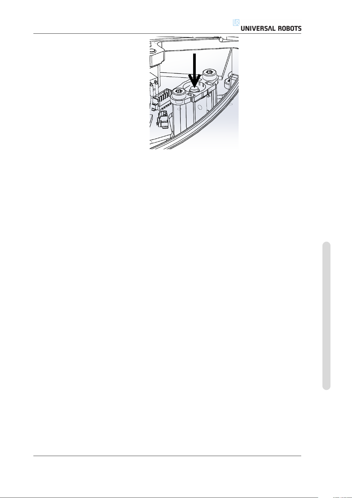
2. Manual brake release (only for Base, Shoulder and Elbow joints): Remove the
joint cover by removing the few M3 screws that fix it. Release the brake by
pushing the plunger on the small electromagnet as shown in the picture below.
Copyright © 2009-2015 by Universal Robots A/S. All rights reserved.
WARNING:
1. Moving the robot arm manually is intended for urgent emer-
gencies only and might damage the joints.
2. If the brake is released manually, gravitational pull can cause
the robot arm to fall. Always support the robot arm, tool and
work item when releasing the brake.
UR3/CB3 I-8 Version 3.1 (rev. 17782)
Page 21
1.9 Movement Without Drive Power
Version 3.1 (rev. 17782)
Copyright © 2009-2015 by Universal Robots A/S. All rights reserved.
I-9 UR3/CB3
Page 22

1.9 Movement Without Drive Power
Copyright © 2009-2015 by Universal Robots A/S. All rights reserved.
UR3/CB3 I-10 Version 3.1 (rev. 17782)
Page 23
2 Transportation
Transport the robot in the original packaging. Save the packaging material in a dry
place; you may need to pack down and move the robot later on.
Lift both tubes of the robot arm at the same time when moving it from the pack-
aging to the installation place. Hold the robot in place until all mounting bolts are
securely tightened at the base of the robot.
The controller box shall be lifted by the handle.
WARNING:
1. Make sure not to overloadyour back or other bodyparts when
the equipment is lifted. Use proper lifting equipment. All
regional and national guidelines for lifting shall be followed.
Universal Robots cannot be held responsible for any damage
caused by transportation of the equipment.
2. Make sure to mount the robot according to the mounting in-
structions in chapter 3.
Version 3.1 (rev. 17782)
Copyright © 2009-2015 by Universal Robots A/S. All rights reserved.
I-11 UR3/CB3
Page 24

Copyright © 2009-2015 by Universal Robots A/S. All rights reserved.
UR3/CB3 I-12 Version 3.1 (rev. 17782)
Page 25

3 Mechanical Interface
The robot consists essentially of six robot joints and two aluminum tubes, connect-
ing the base with the tool of the robot. The robot permits the tool to be translated
and rotated within the workspace. The next section describes the basics of mount-
ing the various parts of the robot system.
Electrical installation instructions in chapter 4 must be observed.
3.1 Workspace of the Robot
The workspace of the UR3 robot extends 500 mm from the base joint. It is important
to consider the cylindrical volume directly above and directly below the robot base
when a mounting place for the robot is chosen. Moving the tool close to the cylin-
drical volume should be avoided if possible, because it causes the joints to move
fast even though the tool is moving slowly, causing the robot to work inefficiently
and the conduction of the risk assessment to be difficult.
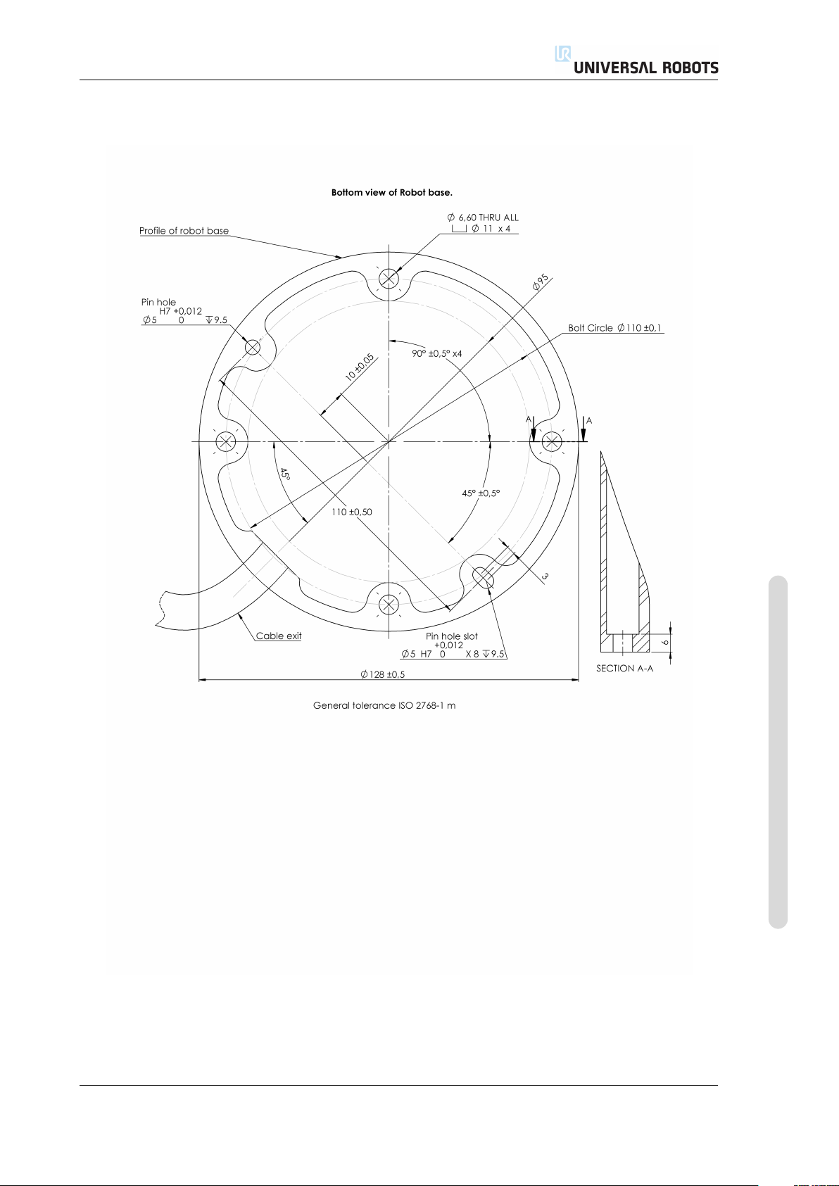
3.2 Mounting
Robot Arm The robot arm is mounted using four M6 bolts, using the four 6.6mm
holes on the base. It is recommended to tighten these bolts with 9 N m torque. If
very accurate repositioning of the robot arm is desired, two Ø5 holes are provided
for use with a pin. Also, an accurate base counterpart can be purchased as an
accessory. Figure 3.1 shows where to drill holes and mount the screws.
The robot connector cable can be mounted through the side or through the bottom
of the base.
Version 3.1 (rev. 17782)
Front Tilted
Copyright © 2009-2015 by Universal Robots A/S. All rights reserved.
I-13 UR3/CB3
Page 26
3.2 Mounting
WARNING:
Remember to insert the rubber plugs in all mounting holes in the
robot base to avoid entrapment of fingers.
Mount the robot on a sturdy surface strong enough to withstand at least ten times
the full torque of the base joint and at least five times the weight of the robot arm.
Furthermore the surface shall be vibration free.
If the robot is mounted on a linear axis or a moving platform then the acceleration
of the moving mounting base shall be very low. A high acceleration might cause
the robot to stop, thinking it bumped into something.
DANGER:
Make sure the robot arm is properly and securely bolted in place.
The mounting surface shall be sturdy.
Copyright © 2009-2015 by Universal Robots A/S. All rights reserved.
CAUTION:
If the robot is bathed in water over an extended time period it
might be damaged. The robot should not be mounted in water
or in a wet environment.
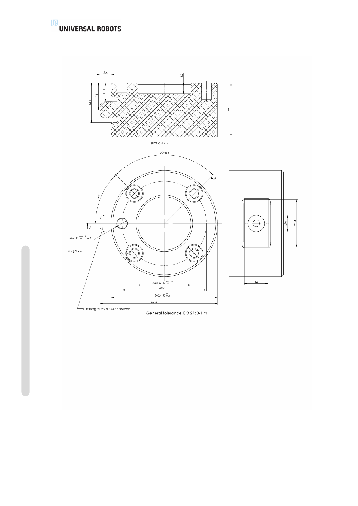
Tool The robot tool flange has four M6 thread holes for attaching a tool to the
robot. The holes need to be tightened with 9 N m. If very accurate repositioning
of the tool is desired, the Ø6 hole is provided for use with a pin. Figure 3.2 shows
where to drill holes and mount the screws.
DANGER:
1. Make sure the tool is properly and securely bolted in place.
2. Make sure that the tool is constructed such that it cannot cre-
ate a hazardous situation by dropping a part unexpectedly.
Control Box The control box can be hung on a wall, or it can be placed on the
ground. A clearance of 50 mm on each side is needed for sufficient airflow. Extra
brackets for mounting can be bought.
Teach Pendant The teach pendant can be hung on a wall or on the control box.
Extra brackets for mounting the teach pendant can be bought. Make sure that no
one can trip over the cable.
UR3/CB3 I-14 Version 3.1 (rev. 17782)
Page 27
3.2 Mounting
Figure 3.1: Holes for mounting the robot. Use four M6 bolts. All measurements are in mm.
Version 3.1 (rev. 17782)
I-15 UR3/CB3
Copyright © 2009-2015 by Universal Robots A/S. All rights reserved.
Page 28
3.2 Mounting
Copyright © 2009-2015 by Universal Robots A/S. All rights reserved.
Figure 3.2: The tool output flange, ISO 9409-1-50-4-M6. This is where the tool is mounted at the tip of
the robot. All measures are in mm.
UR3/CB3 I-16 Version 3.1 (rev. 17782)
Page 29

3.2 Mounting
DANGER:
1. Make sure that the control box, teach pendant, and cables do
not come into contact with liquids. A wet control box could
cause death.
2. The control box and teach pendant must not be exposed to
dusty or wet environments that exceed IP20 rating. Pay spe-
cial attention to environments with conductive dust.
Version 3.1 (rev. 17782)
Copyright © 2009-2015 by Universal Robots A/S. All rights reserved.
I-17 UR3/CB3
Page 30

3.2 Mounting
Copyright © 2009-2015 by Universal Robots A/S. All rights reserved.
UR3/CB3 I-18 Version 3.1 (rev. 17782)
Page 31

4.1 Introduction
This chapter describes all the electrical interfaces of the robot arm and control box.
The different interfaces are divided into five groups with different purposes and
properties:
• Controller I/O
• Tool I/O
• Ethernet
• Mains connection
• Robot connection
The term “I/O” refers both digital and analog control signals going from or to an
interface.
These five groups are described in the following sections. Examples are given for
most types of I/O.
4 Electrical Interface
The warnings and cautions in the following section are relevant for all five groups
and must be observed.
4.2 Electrical warnings and cautions
The following warnings and cautions must be observed when a robot application
is designed and installed. The warnings and cautions also apply for service work.
DANGER:
1. Never connect safety signals to a PLC which is not a safety
PLC with the correct safety level. Failure to follow this warn-
ing could result in serious injury or death as one of safety stop
functions could be overridden. It is important to keep safety
interface signals separated from the normal I/O interface sig-
nals.
2. All safety-related signals are constructed redundantly (Two
independent channels). Keep the two channels separate so
that a single fault cannot lead to loss of the safety function.
3. Some I/O inside the control box can be configured for either
normal or safety-related I/O. Read and understand the com-
plete section 4.3.
Copyright © 2009-2015 by Universal Robots A/S. All rights reserved.
Version 3.1 (rev. 17782)
I-19 UR3/CB3
Page 32

4.2 Electrical warnings and cautions
DANGER:
1. Make sure that all equipment not rated for water exposure
remains dry. If water comes inside the product, lockout and
tagout all power and then contact your supplier.
2. Use original cables supplied with the robot only. Do not use
the robot for applications where the cables will be subjected
to flexing. Contact your supplier if longer or flexible cables
are needed.
3. Minus connections are referred to as “GND” and are con-
nected to the shield of the robot and the controller box. All
mentioned GND connections are only for powering and sig-
nalling. For PE (Protective Earth) use the M6 sized screw con-
nections marked with earth symbols inside the control box.
The grounding conductor shall have at least the current rat-
ing of the highest current in the system.
4. Care must be taken when installing interface cables to the
robot I/O. The metal plate in the bottom is intended for inter-
face cables and connectors. Remove the plate before drilling
the holes. Make sure that all shavings are removed before
reinstalling the plate. Remember to use correct gland sizes.
Copyright © 2009-2015 by Universal Robots A/S. All rights reserved.
CAUTION:
1. The robot has been tested according to international IEC stan-
dards for EMC (ElectroMagnetic Compatibility). Disturbing
signals with levels higher than those defined in the specific
IEC standards can cause unexpected behavior of the robot.
Very high signal levels or excessive exposure can damage the
robot permanently. EMC problems are found to happen usu-
ally in welding processes and are normally prompted by error
messages in the log. Universal Robots cannot be held respon-
sible for any damages caused by EMC problems.
2. I/O cables going from the control box to other machinery and
factory equipment may not be longer than 30m, unless ex-
tended tests are performed.
NOTE:
All voltages and currents are in DC (Direct Current) unless other-
wise specified.
UR3/CB3 I-20 Version 3.1 (rev. 17782)
Page 33

4.3 Controller I/O
24V
EI1
24V
SI0
24V
SI1
24V
EI0
Safety
ON
OFF
12V
Remote
24V
0V
PWR
GND
Power
24V
CI1
24V
CI2
24V
CI3
24V
CI0
Configurable Inputs
24V
CI5
24V
CI6
24V
CI7
24V
CI4
0V
CO1
0V
CO2
0V
CO3
0V
CO0
Configurable Outputs
0V
CO5
0V
CO6
0V
CO7
0V
CO4
24V
DI1
24V
DI2
24V
DI3
24V
DI0
Digital Inputs
24V
DI5
24V
DI6
24V
DI7
24V
DI4
0V
DO1
0V
DO2
0V
DO3
0V
DO0
Digital Outputs
0V
DO5
0V
DO6
0V
DO7
0V
DO4
AG
AI1
AG
AO0
AG
AO1
AG
AI0
Analog
Analog Outputs
Analog Inputs
Safeguard Stop
Emergency Stop
GND
24V
0V
PWR
GND
Power
4.3 Controller I/O
This chapter explains how to connect equipment to I/O inside the control box. This
I/O is extremely flexible and can be used for wide range of different equipment;
including pneumatic relays, PLCs and emergency stop buttons.
The illustration below shows the layout of electrical interface inside the control box.
The meaning of the different colors must be observed, see below.
Yellow with red text Dedicated safety signals
Yellow with black text Configurable for safety
Gray with black text General purpose digital I/O
Green with black text General purpose analog I/O
The “configurable” I/O can be configured as either safety-related I/O or general
purpose I/O in the GUI. See more in part II.
How to use the digital I/O is described in the following subsections. The section
describing the common specifications must be observed.
4.3.1 Common specifications for all digital I/O
This section define electrical specifications for the following 24V digital I/O of the
control box.
• Safety I/O.
• Configurable I/O.
• General purpose I/O.
It is very important that UR robots are installed according the electrical specifica-
tions, which are the same for all three different kinds of inputs.
It is possible to power the digital I/O from an internal 24V power supply or from an
external power source by configuring the terminal block called “Power”. This block
consists of four terminals. The upper two (PWR and GND) are 24V and ground
from the internal 24V supply. The lower two terminals (24V and 0V) in the block
are the 24V input to supply the I/O. The default configuration is to use the internal
power supply, see below.
Copyright © 2009-2015 by Universal Robots A/S. All rights reserved.
Version 3.1 (rev. 17782)
I-21 UR3/CB3
Page 34

4.3 Controller I/O
24V
0V
PWR
GND
Power
If more current is needed, an external power supply can be connected as shown
below.
The electrical specifications for both the internal and an external power supply are
shown below.
Terminals Parameter Min Typ Max Unit
Internal 24V power supply
[PWR - GND] Voltage 23 24 25 V
[PWR - GND] Current 0 - 2 A
External 24V input requirements
[24V - 0V] Voltage 20 24 29 V
[24V - 0V] Current 0 - 6 A
Copyright © 2009-2015 by Universal Robots A/S. All rights reserved.
The digital I/O are constructed in compliance with IEC 61131-2. The electrical spec-
ifications are shown below.
Terminals Parameter Min Typ Max Unit
Digital outputs
[COx / DOx] Current 0 - 1 A
[COx / DOx] Voltage drop 0 - 0.5 V
[COx / DOx] Leakage current 0 - 0.1 mA
[COx / DOx] Function - PNP - Type
[COx / DOx] IEC 61131-2 - 1A - Type
Digital Inputs
[EIx/SIx/CIx/DIx] Voltage -3 - 30 V
[EIx/SIx/CIx/DIx] OFF region -3 - 5 V
[EIx/SIx/CIx/DIx] ON region 11 - 30 V
[EIx/SIx/CIx/DIx] Current (11-30V) 2 - 15 mA
[EIx/SIx/CIx/DIx] Function - PNP - Type
[EIx/SIx/CIx/DIx] IEC 61131-2 - 3 - Type
NOTE:
The word “configurable” is used for I/O that can be configured
as either safety-related I/O or normal I/O. These are the yellow
terminals with black text.
4.3.2 Safety I/O
This section describes the dedicated safety inputs (Yellow terminal with red text)
and the configurable I/O (Yellow terminals with black text) when configured as
safety I/O. The common specifications in section 4.3.1 must be observed.
UR3/CB3 I-22 Version 3.1 (rev. 17782)
Page 35

4.3 Controller I/O
Safety devices and equipment must be installed according to the safety instructions
and the risk assessment, see chapter 1.
All safety I/O are pairwise (redundant) and must be kept as two separate branches.
A single fault shall not cause loss of the safety function.
The two permanent safety inputs are the emergency stop and the safeguard stop.
The emergency stop input is for emergency stop equipment only. The safeguard
stop input is for all kinds of safety-related protective equipment. The functional
difference is shown below.
Emergency Stop Safeguard Stop
Robot stops moving Yes Yes
Program execution Stops Pauses
Robot power Off On
Reset Manual Automatic or manual
Frequency of use Infrequent Every cycle to infrequent
Requires re-initialization Brake release only No
Stop category (IEC 60204) 1 2
Performance level of
monitoring function (ISO 13849-1) PLd PLd
It is possible to use the configurable I/O to set up additional safety I/O function-
ality, e.g. emergency stop output. Configuring a set of configurable I/O for safety
functions are done through the GUI, see part II.
Some examples of how to use safety I/O are shown in the following subsections.
DANGER:
1. Never connect safety signals to a PLC which is not a safety
PLC with the correct safety level. Failure to follow this warn-
ing could result in serious injury or death as one of safety stop
functions could be overridden. It is important to keep safety
interface signals separated from the normal I/O interface sig-
nals.
2. All safety-related I/O are constructed redundantly (Two in-
dependent channels). Keep the two channels separate so that
a single fault cannot lead to loss of the safety function.
3. Safety functions must be verified before putting the robot into
operation. Safety functions must be tested regularly.
4. The robot installation shall conform to these specifications.
Failure to do so could result in serious injury or death as the
safety stop function could be overridden.
Copyright © 2009-2015 by Universal Robots A/S. All rights reserved.
Version 3.1 (rev. 17782)
I-23 UR3/CB3
Page 36

4.3.2.1 Default safety configuration
24V
EI1
24V
SI0
24V
SI1
24V
EI0
Safety
Safeguard Stop
Emergency Stop
24V
EI1
24V
SI0
24V
SI1
24V
EI0
Safety
Safeguard Stop
Emergency Stop
24V
EI1
24V
SI0
24V
SI1
24V
EI0
Safety
Safeguard Stop
Emergency Stop
24V
CI1
24V
CI2
24V
CI3
24V
CI0
Configurable Inputs
24V
CI5
24V
CI6
24V
CI7
24V
CI4
0V
CO1
0V
CO2
0V
CO3
0V
CO0
Configurable Outputs
0V
CO5
0V
CO6
0V
CO7
0V
CO4
24V
CI1
24V
CI2
24V
CI3
24V
CI0
Configurable Inputs
24V
CI5
24V
CI6
24V
CI7
24V
CI4
0V
CO1
0V
CO2
0V
CO3
0V
CO0
Configurable Outputs
0V
CO5
0V
CO6
0V
CO7
0V
CO4
A
B
The robot is shipped with a default configuration which enables operation without
any additional safety equipment, see illustration below.
4.3.2.2 Connecting emergency stop buttons
In most applications it is required to use one or more extra emergency stop buttons.
The illustration below show how one or more emergency stop buttons.
4.3 Controller I/O
Copyright © 2009-2015 by Universal Robots A/S. All rights reserved.
4.3.2.3 Sharing emergency stop with other machines
It is often desired to set up a common emergency stop circuit when the robot is
used together with other machines. By doing so, the operator does not need to
think about which emergency stop buttons to use.
The normal emergency stop input cannot be used for sharing purposes, since both
machines will wait for the each other to go out of the emergency stopped condition.
In order to share the emergency stop function with other machinery, the following
configurable I/O functions must be configured through the GUI.
• Configurable input pair: External emergency stop.
• Configurable output pair: System emergency stop.
The illustration below shows how two UR robots share their emergency stop func-
tions. In this example the configured I/Os used are “CI0-CI1” and “CO0-CO1”.
UR3/CB3 I-24 Version 3.1 (rev. 17782)
Page 37

4.3 Controller I/O
24V
EI1
24V
SI0
24V
SI1
24V
EI0
Safety
Safeguard Stop
Emergency Stop
24V
EI1
24V
SI0
24V
SI1
24V
EI0
Safety
Safeguard Stop
Emergency Stop
24V 0V
24V
0V
If more than two UR robot or other machines needs to be connected, a safety PLC
is needed to control the emergency stop signals.
4.3.2.4 Safeguard stop with automatic resume
An example of a basic safeguard stop device is a door switch where the robot is
stopped when a door is opened, see illustration below.
This configuration is only intended for application where the operator cannot pass
the door and close it behind him. The configurable I/O can be used to setup a reset
button outside the door, to reactivate robot motion.
Another example where automatic resume can be appropriate is when using a
safety mat or a safety-related laser scanner, see below.
DANGER:
1. The robot resumes movement automatically when the safe-
guard signal is re-established. Do not use this configuration
if signal can be re-established from the inside of the safety
perimeter.
4.3.2.5 Safeguard stop with reset button
If the safeguard interface is used to interface a light curtain, a reset outside the
safety perimeter is required. The reset button must be a two channel type. In this
example the I/O configured for reset is “CI0-CI1”, see below.
Version 3.1 (rev. 17782)
I-25 UR3/CB3
Copyright © 2009-2015 by Universal Robots A/S. All rights reserved.
Page 38

24V
EI1
24V
SI0
24V
SI1
24V
EI0
Safety
Safeguard Stop
Emergency Stop
24V 0V
24V
0V
24V
CI1
24V
CI2
24V
CI3
24V
CI0
Configurable Inputs
24V
CI5
24V
CI6
24V
CI7
24V
CI4
4.3.3 General purpose digital I/O
0V
DO1
0V
DO2
0V
DO3
0V
DO0
Digital Outputs
0V
DO5
0V
DO6
0V
DO7
0V
DO4
LOAD
24V
DI1
24V
DI2
24V
DI3
24V
DI0
Digital Inputs
24V
DI5
24V
DI6
24V
DI7
24V
DI4
This section describes the general purpose 24V I/O (Gray terminals) and the con-
figurable I/O (Yellow terminals with black text) when not configured as safety I/O.
The common specifications in section 4.3.1 must be observed.
4.3 Controller I/O
The general purpose I/O can be used to drive equipment like pneumatic relays
directly or for communication with other PLC systems. All digital outputs can be
disabled automatically when program execution is stopped, see more in part II. In
this mode, the output is always low when a program is not running. Examples are
shown in the following subsections. These examples use regular digital outputs
but any configurable outputs could also have be used if they are not configured to
perform a safety function.
4.3.3.1 Load controlled by a digital output
This example shows how to connect a load to be controlled from a digital output,
see below.
4.3.4 Digital input from a button
Copyright © 2009-2015 by Universal Robots A/S. All rights reserved.
The example below shows how to connect a simple button to a digital input.
UR3/CB3 I-26 Version 3.1 (rev. 17782)
Page 39

4.3 Controller I/O
24V
DI1
24V
DI2
24V
DI3
24V
DI0
Digital Inputs
24V
DI5
24V
DI6
24V
DI7
24V
DI4
0V
DO1
0V
DO2
0V
DO3
0V
DO0
Digital Outputs
0V
DO5
0V
DO6
0V
DO7
0V
DO4
24V
DI1
24V
DI2
24V
DI3
24V
DI0
Digital Inputs
24V
DI5
24V
DI6
24V
DI7
24V
DI4
0V
DO1
0V
DO2
0V
DO3
0V
DO0
Digital Outputs
0V
DO5
0V
DO6
0V
DO7
0V
DO4
A B
4.3.5 Communication with other machines or PLCs
The digital I/O can be used to communicate with other equipment if a common
GND (0V) is established and if the machine uses PNP technology, see below.
4.3.6 General purpose analog I/O
The analog I/O interface is the green terminal. It can be used to set or measure
voltage (0-10V) or current (4-20mA) from and to other equipment.
The following is recommended to achieve a high accuracy.
• Use the AG terminal closest to the I/O. The pair share a common mode filter.
• Use the same gnd (0V) for equipment and control box. The analog I/O is not
galvanically isolated from the control box.
• Use a shielded cable or twisted pairs. Connect the shield to the “GND” termi-
nal at the terminal called “Power”.
• Use of equipment that works in current mode. Current signals are less sensi-
tive to interferences.
Input modes can be selected in the GUI, see part II. The electrical specifications are
shown below.
Version 3.1 (rev. 17782)
I-27 UR3/CB3
Copyright © 2009-2015 by Universal Robots A/S. All rights reserved.
Page 40

4.3 Controller I/O
AG
AI1
AG
AO0
AG
AO1
AG
AI0
Analog
Analog Outputs
Analog Inputs
24V
0V
PWR
GND
Power
Terminals Parameter Min Typ Max Unit
Analog input in current mode
[AIx - AG] Current 4 - 20 mA
[AIx - AG] Resistance - 20 - ohm
[AIx - AG] Resolution - 12 - bit
Analog input in voltage mode
[AIx - AG] Voltage 0 - 10 V
[AIx - AG] Resistance - 10 - Kohm
[AIx - AG] Resolution - 12 - bit
Analog output in current mode
[AOx - AG] Current 4 - 20 mA
[AOx - AG] Voltage 0 - 10 V
[AOx - AG] Resolution - 12 - bit
Analog output in voltage mode
[AOx - AG] Voltage 0 - 10 V
[AOx - AG] Current -20 - 20 mA
[AOx - AG] Resistance - 1 - ohm
[AOx - AG] Resolution - 12 - bit
The following examples show how to use the analog I/O.
4.3.6.1 Using an analog output
Below is an example of how to control a conveyor belt with an analog speed control
input.
4.3.6.2 Using an Analog Input
Below is an example of how to connect an analog sensor.
Copyright © 2009-2015 by Universal Robots A/S. All rights reserved.
UR3/CB3 I-28 Version 3.1 (rev. 17782)
Page 41

4.3 Controller I/O
AG
AI1
AG
AO0
AG
AO1
AG
AI0
Analog
Analog Outputs
Analog Inputs
24V
0V
PWR
GND
Power
4.3.7 Remote ON/OFF control
Remote ON/OFF control can be used to turn the control box on and off without
using the teach pendant. It is typically used in the following applications:
• When the teach pendant is inaccessible.
• When a PLC system must have full control.
• When several robots must be turned on or off at the same time.
The remote ON/OFF control provides a small auxiliary 12V supply, which is kept
active when the controller box is turned off. The “on” and “off” inputs are intended
for short time activation only. The on input works in the same way as the power
button. Always use the “off” input for remote off control as this signal allows the
control box safe files and shut down nicely.
The electrical specifications are shown below.
Terminals Parameter Min Typ Max Unit
[12V - GND] Voltage 10 12 13 V
[12V - GND] Current - - 100 mA
[ON / OFF] Inactive voltage 0 - 0.5 V
[ON / OFF] Active voltage 5 - 12 V
[ON / OFF] Input current - 1 - mA
[ON] Activation time 200 - 600 ms
The following examples show how to use remote ON/OFF.
NOTE:
A special feature in the software can be used to load and start pro-
grams automatically, see part II.
Copyright © 2009-2015 by Universal Robots A/S. All rights reserved.
Version 3.1 (rev. 17782)
CAUTION:
1. Never use the “on” input or the power button to turn off the
control box.
I-29 UR3/CB3
Page 42

4.3.7.1 Remote ON button
ON
OFF
12V
Remote
GND
ON
OFF
12V
Remote
GND
The illustration below shows how to connect a remote on button.
4.3.7.2 Remote OFF button
The illustration below shows how to connect a remote off button.
4.4 Tool I/O
4.4 Tool I/O
Copyright © 2009-2015 by Universal Robots A/S. All rights reserved.
At the tool end of the robot there is a small connector with eight pins, see illustration
below.
This connector provides power and control signals for grippers and sensors used
on a specific robot tool. The following industrial cables are suitable:
• Lumberg RKMV 8-354.
The eight wires inside the cable have different colors. The different colors designate
different functions, see table below:
Color Signal
Red 0V (GND)
Gray 0V/+12V/+24V (POWER)
Blue Digital output 8 (DO8)
Pink Digital output 9 (DO9)
Yellow Digital input 8 (DI8)
Green Digital input 9 (DI9)
White Analog input 2 (AI2)
Brown Analog input 3 (AI3)
The internal power supply can be set to either 0V, 12V or 24V at the I/O tab the
GUI, see part II. The electrical specifications are shown below:
UR3/CB3 I-30 Version 3.1 (rev. 17782)
Page 43

4.4 Tool I/O
Parameter Min Typ Max Unit
Supply voltage in 24V mode - 24 - V
Supply voltage in 12V mode - 12 - V
Supply current in both modes - - 600 mA
The following sections describe the different I/O’s of the tool.
DANGER:
1. Construct tools and gripper so that an interruption of power
does not create any hazards. E.g. a work-piece falling out of
the tool.
2. Take care when using 12V, since an error made by the pro-
grammer can cause the voltage to change to 24V, which might
damage the equipment and cause a fire.
NOTE:
The tool flange is connected to GND (same as the red wire).
4.4.1 Tool Digital Outputs
The digital outputs are implemented as NPN. When a digital output is activated
the corresponding connection is driven to GND, and when it is deactivated the cor-
responding connection is open (open-collector/open-drain). The electrical specifi-
cations are shown below:
Parameter Min Typ Max Unit
Voltage when open -0.5 - 26 V
Voltage when sinking 1A - 0.05 0.20 V
Current when sinking 0 - 1 A
Current through GND 0 - 1 A
An example of how to use a digital output is shown in the following subsection.
CAUTION:
1. The digital outputs in the tool are not current limited and
4.4.1.1 Using the Tool Digital Outputs
The example below illustrates how to turn on a load, when using the internal 12V
or 24V power supply. Remember that you have to define the output voltage at the
I/O tab. Keep in mind that there is voltage between the POWER connection and
the shield/ground, even when the load is turned off.
overriding the specified data can cause permanent damage.
Copyright © 2009-2015 by Universal Robots A/S. All rights reserved.
Version 3.1 (rev. 17782)
I-31 UR3/CB3
Page 44

DO8
POWER
4.4.2 Tool Digital Inputs
DI8
POWER
The digital inputs are implemented as PNP with weak pull-down resistors. This
means that a floating input will always read low. The electrical specifications are
shown below.
Parameter Min Typ Max Unit
Input voltage -0.5 - 26 V
Logical low voltage - - 2.0 V
Logical high voltage 5.5 - - V
Input resistance - 47k - Ω
An example of how to use a digital input is shown in the following subsection.
4.4.2.1 Using the Tool Digital Inputs
The example below shows how to connect a simple button.
4.4 Tool I/O
Copyright © 2009-2015 by Universal Robots A/S. All rights reserved.
4.4.3 Tool Analog Inputs
The tool analog inputs are non-differential and can be set to either voltage and
current on the I/O tab, see part II. The electrical specifications are shown below.
Parameter Min Typ Max Unit
Input voltage in voltage mode -0.5 - 26 V
Input voltage in current mode -0.5 - 5.0 V
Input current in current mode -2.5 - 25 mA
Input resistance @ range 0V to 5V - 29 - kΩ
Input resistance @ range 0V to 10V - 15 - kΩ
Input resistance @ range 4mA to 20mA - 200 - Ω
Two examples of how to use an analog inputs are shown in the following subsec-
tions.
CAUTION:
1. Analog inputs are not protected against over voltage in cur-
rent mode. Overrating the limit in the electrical specification
can cause permanent damage to the input.
UR3/CB3 I-32 Version 3.1 (rev. 17782)
Page 45

4.5 Ethernet
GND
POWER
AI8
POWER
AI8
GND
4.4.3.1 Using the Tool Analog Inputs, Non-differential
The example below shows how to connect an analog sensor with a non-differential
output. The output of the sensor can be either current or voltage, as long as the
input mode of that analog input is set to the same on the I/O tab. Remember to
check that a sensor with voltage output can drive the internal resistance of the tool,
or the measurement might be invalid.
4.4.3.2 Using the Tool Analog Inputs, Differential
The example below shows how to connect an analog sensor with a differential out-
put. Connect the negative output part to GND (0V) and it works in the same way
as a non-differential sensor.
4.5 Ethernet
An Ethernet connection is provided at the bottom of the control box, see illustration
below.
The Ethernet interface can be used for the following:
• MODBUS I/O expansion modules. See more in part II.
• Remote access and control.
The electrical specifications are shown below.
Parameter Min Typ Max Unit
Communication speed 10 - 100 Mb/s
Copyright © 2009-2015 by Universal Robots A/S. All rights reserved.
Version 3.1 (rev. 17782)
I-33 UR3/CB3
Page 46

4.6 Mains connection
The mains cable from the controller box has a standard IEC plug in the end. Con-
nect a country specific mains plug or cable to the IEC plug.
In order to energize the robot, the control box must be connected to the mains. This
must be done through the standard IEC C20 plug at the bottom of the control box
through a corresponding IEC C19 cord, see illustration below.
The mains supply shall be equipped with the following as a minimum:
• Connection to earth.
4.6 Mains connection
• Main fuse.
• Residual current device.
It is recommended to install a main switch to power of all equipment in the robot
application as an easy means for lockout and tagout under service.
The electrical specifications are shown in the table below.
Parameter Min Typ Max Unit
Input voltage 100 - 240 VAC
External mains fuse (@ 100-200V) 8 - 16 A
External mains fuse (@ 200-240V) 8 - 16 A
Input frequency 47 - 63 Hz
Stand-by power - - 0.5 W
Nominal operating power 90 150 325 W
Copyright © 2009-2015 by Universal Robots A/S. All rights reserved.
UR3/CB3 I-34 Version 3.1 (rev. 17782)
Page 47

4.7 Robot connection
DANGER:
1. Make sure that the robot is grounded correctly (Electrical
connection to earth). Use the unused bolts associated with
grounding symbols inside the controller box to create com-
mon grounding of all equipment in the system. The ground-
ing conductor shall have at least the current rating of the high-
est current in the system.
2. Make sure that the input power to the controller box is pro-
tected with a RCD (Residual Current Device) and a correct
fuse.
3. Lockout and tagout all power for the complete robot installa-
tion during service. Other equipment shall not supply volt-
age to the robot I/O when the system is locked out.
4. Make sure that all cables are connected correctly before the
controller box is powered. Always use an original and correct
power cord.
4.7 Robot connection
The cable from the robot must be plugged into the connector at bottom of the con-
trol box, see illustration below. Ensure that the connector is properly locked before
turning on the robot arm. Disconnecting the robot cable may only be done when
the robot power is turned off.
CAUTION:
Copyright © 2009-2015 by Universal Robots A/S. All rights reserved.
Version 3.1 (rev. 17782)
1. Do not disconnect the robot cable when the robot arm is
turned on.
2. Do not extend or modify the original cable.
I-35 UR3/CB3
Page 48

4.7 Robot connection
Copyright © 2009-2015 by Universal Robots A/S. All rights reserved.
UR3/CB3 I-36 Version 3.1 (rev. 17782)
Page 49

5 Safety-related Functions and Interfaces
UR robots are equipped with a range of built-in safety-related functions as well
as safety-related electrical interfaces to connect to other machines and additional
protective devices. Each safety function and interface is monitored according to
ISO 13849-1 (see Chapter 8 for certifications) with Performance Level d (PLd).
NOTE:
If the robot discovers a fault in the safety system, e.g. one of the
wires in the emergency stop circuit is cut, or a position sensor is
broken, a category 0 stop is initiated. The worst case reaction time,
from the time an error occurs to the point in time that it is detected,
and the robot is stopped and powered off, is 1250ms.
Part II of the PolyScope Manual describes configuration of the safety-related fea-
tures, inputs, and outputs. See Chapter 4 for descriptions on how to connect safety
devices to the electrical interface.
5.1 Limiting Safety-related Functions
The robot has a number of safety-related functions that can be used to limit the
movement of its joints and of the robot Tool Center Point (TCP). The TCP is the
center point of the output flange with the addition of the TCP offset (see Part II, the
PolyScope Manual).
The limiting safety-related functions are:
Limiting Safety
Function
Joint position Min. and max. angular joint position
Joint speed Max. angular joint speed
TCP position Planes in Cartesian space limiting robot TCP position
TCP speed Max. speed of the robot TCP
TCP force Max. pushing force of the robot TCP
Momentum Max. momentum of the robot arm
Power Max. applied robot arm power
Advanced path control software decreases speed or issues a program execution
stop if the robot arm approaches a safety-related limit. Violations of limits will
hence only occur in exceptional cases. Nevertheless, if a limit is violated, the safety
system issues a category 0 stop with the performance listed in the table:
Description
Copyright © 2009-2015 by Universal Robots A/S. All rights reserved.
Version 3.1 (rev. 17782)
I-37 UR3/CB3
Page 50

5.1 Limiting Safety-related Functions
450 mm
200 mm
Figure 5.1: Certain areas of the workspace should receive attention regarding pinching hazards, due to
the physical properties of the robot arm. One area is defined for radial motions, when the wrist 1 joint
is at a distance of at least 450mm from the base of the robot. The other area is within 200mm of the base
of the robot, when moving in the tangential direction.
Worst Case
Limiting Safety
Function
Joint position 1.15
Joint speed 1.15◦/s 250 ms 1000 ms 1250 ms
TCP position 20 mm 100ms 1000 ms 1100 ms
TCP orientation 1.15
TCP speed 50mm/s 250 ms 1000 ms 1250 ms
TCP force 25 N 250 ms 1000 ms 1250 ms
Momentum 3
Power 10 W 250 ms 1000 ms 1250 ms
Trueness Detection
Time
◦
◦
kg m
100 ms 1000 ms 1100 ms
100 ms 1000 ms 1100 ms
/s 250 ms 1000 ms 1250 ms
De-energizing
Time
Reaction
Time
Copyright © 2009-2015 by Universal Robots A/S. All rights reserved.
The system is considered de-energized when the 48 V bus voltage reaches an electri-
cal potential below 7.3 V. The de-energizing time is the time from a detection of an
event until the system has been de-energized.
WARNING:
There are two exceptions to the force limiting function that are im-
portant to notice when designing the work cell for the robot. These
are illustrated in Figure 5.1. As the robot stretches out, the knee-
joint effect can give high forces in the radial direction (away from
the base), but at the same time, low speeds. Similarly, the short
leverage arm, when the tool is close to the base and moving tan-
gential (around) the base, can cause high forces, but also at low
speeds. Pinching hazards can be avoided for instance by, removing
obstacles in these areas, placing the robot differently, or by using a
combination of safety planes and joint limits to remove the hazard
by preventing the robot moving into this region of its workspace.
UR3/CB3 I-38 Version 3.1 (rev. 17782)
Page 51

5.2 Safety Modes
5.2 Safety Modes
Normal and Reduced mode The safety system has two configurable safety modes:
Normal and Reduced. Safety limits can be configured for each of these two modes.
Reduced mode is active when the robot TCP is positioned beyond a Trigger Reduced
mode plane or when triggered by a safety input.
On the side of the Trigger Reduced mode planes where the normal mode limit set is
defined, there is an area of 20 mm where the reduced mode limit set is accepted.
When Reduced mode is triggered by a safety input, both limit sets are accepted for
500 ms.
Recovery Mode When a safety limit is violated, the safety system must be restarted.
If the system is outside a safety limit at start-up (e.g. outside a joint position limit),
the special Recovery mode is entered. In Recovery mode it is not possible to run pro-
grams for the robot, but the robot arm can be manually moved back within limits
either by using Freedrive mode or by using the Move tab in PolyScope (see part II of
the PolyScope Manual). The safety limits of Recovery mode are:
Limiting Safety Function Limit
Joint speed 30◦/s
TCP speed 250mm/s
TCP force 100 N
Momentum 10
Power 80 W
The safety system issues a category 0 stop if a violation of these limits appears.
WARNING:
Notice that limits for the joint position, the TCP position, and the
TCP orientation are disabled in Recovery Mode. Take caution when
moving the robot arm back within the limits.
5.3 Safety-related Electrical Interfaces
The robot is equipped with several safety-related electrical inputs and outputs. All
safety-related electrical inputs and outputs are dual channel. They are safe when
low, e.g. the emergency stop is not active when the signal is high (+24V).
kg m
/s
Copyright © 2009-2015 by Universal Robots A/S. All rights reserved.
5.3.1 Safety-related Electrical Inputs
The table below gives an overview of the safety-related electrical inputs.
Version 3.1 (rev. 17782)
I-39 UR3/CB3
Page 52

5.3 Safety-related Electrical Interfaces
Max joint
speed in
normal
mode
[rad/s]
[s]
time
0.5240.024
Figure 5.2: The green area below the ramp is the allowed speeds for a joint during braking. At time 0 an
event (emergency stop or safeguard stop) is detected at the safety processor. Deceleration begins after
24 ms.
Safety Input Description
Robot emergency stop Performs a category 1 stop, informing other machines
using the System emergency stop output.
Emergency stop button Performs a category 1 stop, informing other machines
using the System emergency stop output.
System emergency stop Performs a category 1 stop.
Safeguard stop Performs a category 2 stop.
Safeguard reset input Resumes the robot from a Safeguard stopped state, when
an edge on the Safeguard reset input occurs.
Reduced mode The safety system transitions to Reduced mode limits.
Copyright © 2009-2015 by Universal Robots A/S. All rights reserved.
A category 1 and 2 stop decelerates the robot with drive power on, which enables
the robot to stop without deviating from its current path.
Monitoring of safety inputs Category 1 and 2 stops are monitored by the safety
system in the following way:
1. The safety system monitors that the braking initiates within 24 ms, see Fig-
ure 5.2.
2. If a joint is moving, its speed is monitored to never be higher than the speed
obtained by constantly decelerating from the maximum joint speed limit for
Normal mode to 0
3. If a joint is at rest (joint speed is less than 0.2
rad
/s in 500 ms.
rad
/s), it is monitored that it does
not move more than 0.05 rad from the position it had when the speed was
measured below 0.2
rad
/s.
Additionally, for a category 1 stop, the safety system monitors that after the robot
arm is at rest, the powering off is finalized within 600 ms. Furthermore, after a
safeguard stop input, the robot arm is only allowed to start moving again after a
positive edge on the safeguard reset input occurs. If any of the above properties are
not satisfied, the safety system issues a category 0 stop.
UR3/CB3 I-40 Version 3.1 (rev. 17782)
Page 53

5.3 Safety-related Electrical Interfaces
A transition to Reduced mode triggered by the reduced mode input is monitored as
follows:
1. The safety system accepts both Normal and Reduced mode limit sets for 500ms
after the reduced mode input is triggered.
2. After 500 ms, only the Reduced mode limits are in effect.
If any of the above properties are not satisfied, the safety system issues a category
0 stop.
A category 0 stop is performed by the safety system with the performance de-
scribed in the following table. The worst-case reaction time is the time to stop and
to de-energize (discharge to an electrical potential below 7.3 V) a robot running at
full speed and payload.
Safety Input Function Detection
Robot emergency stop 250 ms 1000 ms 1250 ms
Emergency stop button 250 ms 1000 ms 1250 ms
System emergency stop 250 ms 1000 ms 1250 ms
Safeguard stop 250ms 1000 ms 1250 ms
Time
Worst Case
De-energizing
Time
Reaction
Time
5.3.2 Safety-related Electrical Outputs
The table below gives an overview of the safety-related electrical outputs:
Safety Output Description
System emergency stop Activated by an active Robot emergency stop input or by
Robot moving While this signal is inactive, no single joint of the robot
Robot not stopping Inactive when the robot arm has been requested to stop
Reduced mode Active when the safety system is in Reduced mode.
Not reduced mode The Reduced mode output negated.
If a safety output is not set properly, the safety system issues a category 0 stop, with
the following worst-case reaction times:
Safety Output Worst Case Reaction Time
System emergency stop 1100 ms
Robot moving 1100 ms
Robot not stopping 1100 ms
Reduced mode 1100 ms
Not reduced mode 1100 ms
the Emergency stop button.
arm moves more than 0.1 rad.
and has not stopped yet.
Copyright © 2009-2015 by Universal Robots A/S. All rights reserved.
Version 3.1 (rev. 17782)
I-41 UR3/CB3
Page 54

5.3 Safety-related Electrical Interfaces
Copyright © 2009-2015 by Universal Robots A/S. All rights reserved.
UR3/CB3 I-42 Version 3.1 (rev. 17782)
Page 55

6 Maintenance and Repair
It is essential for both maintenance and repair work that it be performed in compli-
ance with all safety instructions in this manual.
Maintenance, calibration and repair work must be performed according to the newest
versions of Service Manuals found on the support website http://support.
universal-robots.com. All UR distributors have access to this support site.
Repairs shall only be performed by authorized system integrators or by Universal
Robots.
All parts returned to Universal Robots shall be returned according to the service
manual.
6.1 Safety Instructions
After maintenance and repair work, checks must be carried out to ensure the re-
quired safety level. The valid national or regional work safety regulations must be
observed for this check. The correct functioning of all safety functions shall also be
tested.
The purpose of maintenance and repair work is to ensure that the system is kept
operational or, in the event of a fault, to return the system to an operational state.
Repair work includes troubleshooting in addition to the actual repair itself.
The following safety procedures and warnings must be observed when working on
the robot arm or control box.
DANGER:
1. Do not change anything in the safety configuration of the
software (e.g. the force limit). The safety configuration is de-
scribed in the PolyScope Manual. If any safety parameter is
changed, the complete robot system shall be considered new,
meaning that the overall safety approval process, including
risk assessment, shall be updated accordingly.
2. Replace faulty components using new components with the
same article numbers or equivalent components approved by
Universal Robots for this purpose.
3. Reactivate any deactivated safety measures immediately after
the work is completed.
Copyright © 2009-2015 by Universal Robots A/S. All rights reserved.
Version 3.1 (rev. 17782)
4. Document all repairs andsave this documentation in the tech-
nical file associated with the complete robot system.
I-43 UR3/CB3
Page 56

6.1 Safety Instructions
DANGER:
1. Remove the mains input cable from the bottom of the control
box to ensure that it is completely unpowered. Deenergize
any other source of energy connected to the robot arm or con-
trol box. Take necessary precautions to prevent other persons
from energizing the system during the repair period.
2. Check the earth connection before re-powering the system.
3. Observe ESD regulations when parts of the robot arm or con-
trol box are disassembled.
4. Avoid disassembling the power supplies inside the control
box. High voltages (up to 600 V) can be present inside these
power supplies for several hours after the control box has
been switched off.
5. Prevent water and dust from entering the robot arm or control
box.
Copyright © 2009-2015 by Universal Robots A/S. All rights reserved.
UR3/CB3 I-44 Version 3.1 (rev. 17782)
Page 57

7 Disposal and Environment
UR robots must be disposed of in accordance with the applicable national laws,
regulations and standards.
UR robots are produced with restricted use of hazardous substances to protect the
environment; as defined by the European RoHS directive 2011/65/EU. These sub-
stances include mercury, cadmium, lead, chromium VI, polybrominated biphenyls
and polybrominated diphenyl ethers.
Fee for disposal and handling of electronic waste of UR robots sold on the Danish
market is prepaid to DPA-system by Universal Robots A/S. Importers in countries
covered by the European WEEE Directive 2012/19/EU must make their own regis-
tration to the national WEEE register of their country. The fee is typically less than
1€/robot. A list of national registers can be found here: https://www.ewrn.
org/national-registers.
The following symbols are affixed on the robot to indicate conformity with the
above legislations:
Version 3.1 (rev. 17782)
Copyright © 2009-2015 by Universal Robots A/S. All rights reserved.
I-45 UR3/CB3
Page 58

Copyright © 2009-2015 by Universal Robots A/S. All rights reserved.
UR3/CB3 I-46 Version 3.1 (rev. 17782)
Page 59

8 Certifications
This chapter presents a range of different certifications and declarations that have
been prepared for the product.
8.1 Third Party Certifications
Third party certifications are voluntary. However, to provide the best service to
robot integrators, UR has chosen to certify their robots at the following recognized
test institutes:
T¨UV NORD UR robots are safety approved by T¨UV NORD,
a notified body under the machinery directive
2006/42/EC in EU. A copy of the T¨UV NORD
safety approval certificate can be found in ap-
pendix B.
DELTA UR robots are safety and performance tested by
DELTA. An electromagnetic compatibility (EMC)
certificate can be found in appendix B. An en-
vironmental test certificate can be found in ap-
pendix B.
8.2 Declarations According to EU directives
EU declarations are primarily relevant for European countries. However, some
countries outside Europe recognize or even require them, too. European directives
are available from the official homepage: http://eur-lex.europa.eu.
UR robots are certified according to the directives listed below.
2006/42/EC — Machinery Directive (MD)
UR Robots are partly completed machinery according to the Machinery Directive
2006/42/EC. Note that a CE mark is not affixed according to this directive for partly
completed machinery. If the UR robot is used in a pesticide application, then note
the presence of directive 2009/127/EC. The declaration of incorporation according
to 2006/42/EC annex II 1.B. is shown in appendix B.
2006/95/EC — Low Voltage Directive (LVD)
2004/108/EC — Electromagnetic Compatibility (EMC)
2011/65/EU — Restriction of the use of certain Hazardous Substances (RoHS)
2012/19/EU — Waste of Electrical and Electronic Equipment (WEEE)
Declarations of conformity with the above Directives are included in the declara-
tion of incorporation in appendix B.
Copyright © 2009-2015 by Universal Robots A/S. All rights reserved.
Version 3.1 (rev. 17782)
I-47 UR3/CB3
Page 60

8.2 Declarations According to EU directives
A CE mark is affixed according to CE marking directives above. Regarding waste
of electric and electronic equipment see chapter 7.
For information about standards applied during the development of the robot, see
appendix C.
Copyright © 2009-2015 by Universal Robots A/S. All rights reserved.
UR3/CB3 I-48 Version 3.1 (rev. 17782)
Page 61

9.1 Product Warranty
Without prejudice to any claim the user (customer) may have in relation to the
dealer or retailer, the customer shall be granted a manufacturer’s Warranty under
the conditions set out below:
In the case of new devices and their components exhibiting defects resulting from
manufacturing and/or material faults within 12 months of entry into service (max-
imum of 15 months from shipment), Universal Robots shall provide the necessary
spare parts, while the user (customer) shall provide working hours to replace the
spare parts, either replace the part with another part reflecting the current state of
the art, or repair the said part. This Warranty shall be invalid if the device defect
is attributable to improper treatment and/or failure to comply with information
contained in the user guides. This Warranty shall not apply to or extend to services
performed by the authorized dealer or the customer themselves (e.g. installation,
configuration, software downloads). The purchase receipt, together with the date
of purchase, shall be required as evidence for invoking the Warranty. Claims un-
der the Warranty must be submitted within two months of the Warranty default
becoming evident. Ownership of devices or components replaced by and returned
to Universal Robots shall vest in Universal Robots. Any other claims resulting out
of or in connection with the device shall be excluded from this Warranty. Nothing
in this Warranty shall attempt to limit or exclude a Customer’s Statutory Rights
nor the manufacturer’s liability for death or personal injury resulting from its neg-
ligence. The duration of the Warranty shall not be extended by services rendered
under the terms of the Warranty. Insofar as no Warranty default exists, Universal
Robots reserves the right to charge the customer for replacement or repair. The
above provisions do not imply a change in the burden of proof to the detriment
of the customer. In case of a device exhibiting defects, Universal Robots shall not
be liable for any indirect, incidental, special or consequential damages, including
but not limited to, lost profits, loss of use, loss of production or damage to other
production equipment.
9 Warranties
In case of a device exhibiting defects, Universal Robots shall not cover any conse-
quential damage or loss, such as loss of production or damage to other production
equipment.
9.2 Disclaimer
Universal Robots continues to improve reliability and performance of its products,
and therefore reserves the right to upgrade the product without prior warning.
Universal Robots takes every care that the contents of this manual are precise and
correct, but takes no responsibility for any errors or missing information.
Version 3.1 (rev. 17782)
Copyright © 2009-2015 by Universal Robots A/S. All rights reserved.
I-49 UR3/CB3
Page 62

9.2 Disclaimer
Copyright © 2009-2015 by Universal Robots A/S. All rights reserved.
UR3/CB3 I-50 Version 3.1 (rev. 17782)
Page 63

A Stopping Time and Stopping Distance
The information about stopping times and distances is available for both CATE-
GORY 0 and CATEGORY 1 stops. This appendix includes the information re-
garding stop CATEGORY 0. Information on CATEGORY 1 stop is available on
http://support.universal-robots.com/.
A.1 CATEGORY 0 stopping distances and times
The table below includes the stopping distances and times measured when a CAT-
EGORY 0 stop is triggered. These measurements correspond to the following con-
figuration of the robot:
• Extension: 100% (the robot arm is fully extended horizontally).
• Speed: 100% (the general speed of the robot is set to 100% and the movement
is performed at a joint speed of 183◦/s).
• Payload: maximum payload handled by the robot attached to the TCP (3 kg).
The test on the Joint 0 was carried out by performing a horizontal movement, i.e.
the axis of rotation was perpendicular to the ground. During the tests for Joint 1
and 2 the robot followed a vertical trajectory, i.e. the axes of rotation were parallel to
the ground, and the stop was performed while the robot was moving downwards.
Stopping Distance (rad) Stopping time (ms)
Joint 0 (BASE) 0.18 159
Joint 1 (SHOULDER) 0.20 154
Joint 2 (ELBOW) 0.15 92
Copyright © 2009-2015 by Universal Robots A/S. All rights reserved.
Version 3.1 (rev. 17782)
I-51 UR3/CB3
Page 64

A.1 CATEGORY 0 stopping distances and times
Copyright © 2009-2015 by Universal Robots A/S. All rights reserved.
UR3/CB3 I-52 Version 3.1 (rev. 17782)
Page 65

B Declarations and Certificates
B.1 CE Declaration of Incorporation (original)
According to European directive 2006/42/EC annex II 1.B.
The manufacturer Universal Robots A/S
Energivej 25
5260 Odense S
Denmark
+45 8993 8989
hereby declares that the product described below
Industrial robot UR3
Robot serial number
Control box serial number
may not be put into service before the machinery in which it will be incorporated is declared to comply
with the provisions of Directive 2006/42/EC, as amended by Directive 2009/127/EC, and with the
regulations transposing it into national law.
The safety features of the product are prepared for compliance with all essential requirements of Direc-
tive 2006/42/EC under the correct incorporation conditions, see product manual. Compliance with all
essential requirements of Directive 2006/42/EC relies on the specific robot installation and the final risk
assessment.
Relevant technical documentation is compiled according to Directive 2006/42/EC annex VII part B.
Additionally the product declares in conformity with the following directives, according to which the
product is CE marked:
2006/95/EC — Low Voltage Directive (LVD)
2004/108/EC — Electromagnetic Compatibility Directive (EMC)
2011/65/EU — Restriction of the use of certain hazardous substances (RoHS)
A complete list of applied harmonized standards, including associated specifications, is provided in the
product manual. This list is valid for the product manual with the same serial numbers as this document
and the product.
Odense, January 27th, 2015
R&D
Lasse Kieffer
Global Compliance Officer
Copyright © 2009-2015 by Universal Robots A/S. All rights reserved.
Version 3.1 (rev. 17782)
I-53 UR3/CB3
Page 66

B.2 Safety System Certificate
B.2 Safety System Certificate
Copyright © 2009-2015 by Universal Robots A/S. All rights reserved.
UR3/CB3 I-54 Version 3.1 (rev. 17782)
Page 67

B.3 Environmental Test Certificate
DELTA - Venlighedsvej 4 - 2970 Hørsholm - Denmark - Tel. +45 72 19 40 00 - Fax +45 72 19 40 01 - www.delta.dk
20a ss- shee t-j
Climatic and mechanical assessment sheet no. 1375
DELTA client
DELTA project no.
Universal Robots A/S
Energivej 25
5260 Odense S
Denmark
T209612 and T209963
Product identification
Robot system UR3, consisting of:
UR3 Robot Arm
CB 3.1 Control Box
TP 3.1 Teach Pendant
DELTA report(s)
DELTA project no. T209612, DANAK-19/14749
DELTA project no. T209963, DANAK-19/14964
Other document(s)
Conclusion
The Robot system UR3 including its Robot Arm, Control Box and Teach Pendant has been tested according to the
below listed standards. The test results are given in the DELTA report listed above. The tests were carried out as
specified and the test criteria for environmental tests, as specified in the annexes of the test reports mentioned above,
were fulfilled.
IEC 60068-2-1:2007, Test Ae: -5 °C, 16 h
IEC 60068-2-2:2007, Test Be: +50 °C, 16 h
IEC 60068-2-27:2008, Test Ea: 160 g, 1 ms, 3 x 6 shocks
IEC 60068-2-64:2008, Test Fh: 5 – 10 Hz: 0.0025 (m/s2)2/Hz, 10 – 50 Hz: 0.04 (m/s2)2/Hz, 100 Hz: 0.0025
(m/s2)2/Hz, 1.5 m/s2 (0.15 grms), 3 x 30 min.
Date
Assessor
Hørsholm, 06 February 2015
Susanne Otto
B.Sc.E.E., B.Com (Org)
B.3 Environmental Test Certificate
Version 3.1 (rev. 17782)
I-55 UR3/CB3
Copyright © 2009-2015 by Universal Robots A/S. All rights reserved.
Page 68

B.4 EMC Test Certificate
The pro duct iden tifi ed above has been as sessed and complies with the spec ified standards /nor mativ e
doc umen ts. T he a ttes tatio n does no t in clude any market surveil lance. It is th e re spon sibi lity of the
man ufac turer tha t mas s-produced apparatus hav e the sam e EMC qua lity . The att est ation does n ot contain
any sta tements per tain ing to th e EM C pro tect ion requi remen ts p ursu ant to othe r la ws and/or dir ectiv es o ther
tha n th e above m enti oned if a ny.
Hørsholm, 20 November 2014
Jakob Steensen
Principal Consultant
DEL TA
Ven lighe dsvej 4
297 0 Hørshol m
Den mark
Tel . +45 72 1 9 40 00
Fax + 45 72 19 4 0 01
www .delt a.dk
VAT No. 1227 5110
20a oca ss-uk -j
Attestation of Conformity
EMC assessment - Certificate no. 1351
Fro m 29 June 200 7 DELTA h as be en d esig nated as Notif ied Body by t he notified aut hori ty National
Tel ecom Agen cy i n Den mark to carry out task s re ferre d to in Annex III of t he Europe an C ouncil EM C
Dir ecti ve 20 04/1 08/EC. T he attestati on o f co nform ity is in acc ordance with Article 5 and refers to the
ess enti al re quir ements set out in A nnex I.
.
DELTA client
Universal Robots A/S
Energivej 25
5260 Odense S
Denmark
Product identification
UR robot generation 3, G3, including CB3/AE for models UR3, UR5 and UR10
Manufacturer
Universal Robots A/S
Technical report(s)
DELTA Project T207371, EMC Test of UR5 and UR10 - DANAK-19/13884, dated 26 March 2014
DELTA Project T209172, EMC Test of UR3 - DANAK-19/14667, dated 05 November 2014
UR EMC Test Specification G3 rev 3, dated 30 October 2014
EMC Assessment Sheet 1351dpa
Standards/Normative documents
EMC Directive 2004/108/EC, Article 5
EN/(IEC) 61326-3-1:2008, Industrial locations, SIL 2 applications
EN/(IEC) 61000-6-2:2005
EN/(IEC) 61000-6-4:2007+A1
B.4 EMC Test Certificate
Copyright © 2009-2015 by Universal Robots A/S. All rights reserved.
UR3/CB3 I-56 Version 3.1 (rev. 17782)
Page 69

C Applied Standards
This section describes relevant standards applied under the development of the robot arm and control
box. Whenever a European Directive number is noted in brackets, it indicates that the standard is
harmonized according to that Directive.
A standard is not a law. A standard is a document developed by stakeholders within a given industry,
defining the normal safety and performance requirements for a product or product group.
Standard type abbreviations mean the following:
ISO International Standardization Organization
IEC International Electrotechnical Commission
EN European Norm
TS Technical Specification
TR Technical Report
ANSI American National Standards Institute
RIA Robotic Industries Association
CSA Canadian Standards Association
Conformity with the following standards is only guaranteed if all assembly instructions, safety instruc-
tions and guidance in this manual are followed.
ISO 13849-1:2006 [PLd]
ISO 13849-2:2012
EN ISO 13849-1:2008 (E) [PLd – 2006/42/EC]
EN ISO 13849-2:2012 (E) (2006/42/EC)
Safety of machinery – Safety-related parts of control systems
Part 1: General principles for design
Part 2: Validation
The safety control system is designed as Performance Level d (PLd) according to the requirements of
these standards.
ISO 13850:2006 [Stop category 1]
EN ISO 13850:2008 (E) [Stop category 1 - 2006/42/EC]
Safety of machinery – Emergency stop – Principles for design
The emergency stop function is designed as a stop category 1 according to this standard. Stop category
1 is a controlled stop with power to the motors to achieve the stop and then removal of power when the
stop is achieved.
Copyright © 2009-2015 by Universal Robots A/S. All rights reserved.
Version 3.1 (rev. 17782)
I-57 UR3/CB3
Page 70

ISO 12100:2010
EN ISO 12100:2010 (E) [2006/42/EC]
Safety of machinery – General principles for design – Risk assessment and risk reduction
UR robots are evaluated according to the principles of this standard.
ISO 10218-1:2011
EN ISO 10218-1:2011(E) [2006/42/EC]
Robots and robotic devices – Safety requirements for industrial robots
Part 1: Robots
This standard is intended for the robot manufacturer, not the integrator. The second part (ISO 10218-2)
is intended for the robot integrator, as it deals with the installation and design of the robot application.
The writers of the standard implicitly envisioned traditional industrial robots, which are traditionally
safeguarded by fences and light curtains. UR robots are designed with force and power limiting enabled
at all times. Therefore, some concepts are clarified and explained below.
If a UR robot is used in a hazardous application, additional safety measures might be required, see
chapter 1 of this manual.
Copyright © 2009-2015 by Universal Robots A/S. All rights reserved.
Clarification:
• “3.24.3 Safeguarded space” is defined by the perimeter safeguarding. Typically, the safeguarded
space is a space behind a fence, which protects people from the hazardous traditional robots. UR
robots are designed to work without a fence using a built-in power and force limiting safety func-
tion, where there is no hazardous safeguarded space defined by the perimeter of a fence.
• “5.4.2 Performance requirement”. All safety functions are constructed as PLd according to ISO 13849-
1:2006. The robot is constructed with redundant encoder systems in each joint, and the safety-rated
I/Os are constructed with a category 3 structure. The safety-rated I/Os must be connected accord-
ing to this manual to category 3 safety-rated equipment to form a PLd structure of the complete
safety function.
• “5.7 Operating modes”. UR robots do not have different operating modes and therefore they do not
have a mode selector.
• “5.8 Pendant controls”. This section defines protective features for the teach pendant, when it is to
be used within a hazardous safeguarded space. Since UR robots are power and force limited, there
is no hazardous safeguarded space like with traditional robots. UR robots are safer to teach than
traditional robots. Instead of having to release a three-positioning enabling device, the operator can
simply stop the robot with his hand.
• “5.10 Collaborative operation requirements”. The power and force limiting function of UR robots is
always active. The visual design of the UR robots indicates that the robots are capable of being used
for collaborative operations. The power and force limiting function is designed according to clause
5.10.5.
• “5.12.3 Safety-rated soft axis and space limiting”. This safety function is one of more safety func-
tions configurable through software. A hash code is generated from the sittings of all these safety
functions and is represented as a safety check identifier in the GUI.
UR3/CB3 I-58 Version 3.1 (rev. 17782)
Page 71

ISO/DTS 15066 (Draft)
Robots and robotic devices – Safety requirements for industrial robots – Collaborative operation
This is a Technical Specification (TS) under preparation. A TS is not a standard. The purpose of a TS is
to present a set of immature requirements to see if they are useful for a given industry.
This TS presents technologies and force-related safety limits for collaborative robots, where the robot
and the human work together to perform a work task.
Universal Robots is an active member of the international committee that develops this TS (ISO/TC
184/SC 2). A final version might be published in 2016.
ANSI/RIA R15.06-2012
Industrial Robots and Robot Systems – Safety Requirements
This American standard is the ISO standards ISO 10218-1 (see above) and ISO 10218-2 combined into
one document. The language is changed from British English to American English, but the content is
the same.
Note that part two (ISO 10218-2) of this standard is intended for the integrator of the robot system, and
not Universal Robots.
CAN/CSA-Z434-14
Industrial Robots and Robot Systems – General Safety Requirements
This Canadian standard is the ISO standards ISO 10218-1 (see above) and -2 combined into one docu-
ment. CSA added additional requirements for the user of the robot system. Some of these requirements
might need to be addressed by the robot integrator.
Note that part two (ISO 10218-2) of this standard is intended for the integrator of the robot system, and
not Universal Robots.
IEC 61000-6-2:2005
IEC 61000-6-4/A1:2010
EN 61000-6-2:2005 [2004/108/EC]
EN 61000-6-4/A1:2011 [2004/108/EC]
Electromagnetic compatibility (EMC)
Part 6-2: Generic standards - Immunity for industrial environments
Part 6-4: Generic standards - Emission standard for industrial environments
These standards define requirements for the electrical and electromagnetic disturbances. Conforming
to these standards ensures that the UR robots perform well in industrial environments and that they do
not disturb other equipment.
Copyright © 2009-2015 by Universal Robots A/S. All rights reserved.
Version 3.1 (rev. 17782)
I-59 UR3/CB3
Page 72

IEC 61326-3-1:2008
EN 61326-3-1:2008
Electrical equipment for measurement, control and laboratory use - EMC requirements
Part 3-1: Immunity requirements for safety-related systems and for equipment intended to perform safety-related
functions (functional safety) - General industrial applications
This standard defines extended EMC immunity requirements for safety-related functions. Conforming
to this standard ensures that the safety functions of UR robots provide safety even if other equipment
exceeds the EMC emission limits defined in the IEC 61000 standards.
IEC 61131-2:2007 (E)
EN 61131-2:2007 [2004/108/EC]
Programmable controllers
Part 2: Equipment requirements and tests
Both normal and safety-rated 24V I/Os are constructed according to requirements of this standard to
ensure reliable communication with other PLC systems.
ISO 14118:2000 (E)
EN 1037/A1:2008 [2006/42/EC]
Copyright © 2009-2015 by Universal Robots A/S. All rights reserved.
Safety of machinery – Prevention of unexpected start-up
These two standards are very similar. They define safety principles for avoiding unexpected start-up,
both as a result of unintended repowering during maintenance or repair, and as a result of unintended
start-up commands from a control perspective.
IEC 60947-5-5/A1:2005
EN 60947-5-5/A11:2013 [2006/42/EC]
Low-voltage switchgear and controlgear
Part 5-5: Control circuit devices and switching elements - Electrical emergency stop device with mechanical
latching function
The direct opening action and the safety lock mechanism of the emergency stop button comply with
requirements in this standard.
IEC 60529:2013
EN 60529/A2:2013
Degrees of protection provided by enclosures (IP Code)
This standard defines enclosure ratings regarding protection against dust and water. UR robots are
designed and classified with an IP code according to this standard, see robot sticker.
UR3/CB3 I-60 Version 3.1 (rev. 17782)
Page 73

IEC 60320-1/A1:2007
EN 60320-1/A1:2007 [2006/95/EC]
Appliance couplers for household and similar general purposes
Part 1: General requirements
The mains input cable complies with this standard.
ISO 9409-1:2004 [Type 50-4-M6]
Manipulating industrial robots – Mechanical interfaces
Part 1: Plates
The tool flange on UR robots conforms to type 50-4-M6 of this standard. Robot tools should also be
constructed according to this standard to ensure proper fitting.
ISO 13732-1:2006
EN ISO 13732-1:2008 [2006/42/EC]
Ergonomics of the thermal environment – Methods for the assessment of human responses to contact with surfaces
Part 1: Hot surfaces
The UR robots are designed so that the surface temperature is kept under the ergonomic limits defined
in this standard.
IEC 61140/A1:2004
EN 61140/A1:2006 [2006/95/EC]
Protection against electric shock – Common aspects for installation and equipment
UR robots are constructed in compliance with this standard to provide protection against electrical
shock. A protective earth/ground connection is mandatory, as defined in the Hardware Installation
Manual.
IEC 60068-2-1:2007
IEC 60068-2-2:2007
IEC 60068-2-27:2008
IEC 60068-2-64:2008
EN 60068-2-1:2007
EN 60068-2-2:2007
EN 60068-2-27:2009
EN 60068-2-64:2008
Environmental testing
Copyright © 2009-2015 by Universal Robots A/S. All rights reserved.
Part 2-1: Tests - Test A: Cold
Part 2-2: Tests - Test B: Dry heat
Part 2-27: Tests - Test Ea and guidance: Shock
Version 3.1 (rev. 17782)
I-61 UR3/CB3
Page 74

Part 2-64: Tests - Test Fh: Vibration, broadband random and guidance
UR robots are tested according to the test methods defined in these standards.
IEC 61784-3:2010
EN 61784-3:2010 [SIL 2]
Industrial communication networks – Profiles
Part 3: Functional safety fieldbuses – General rules and profile definitions
This standards defines requirements for safety-rated communication buses.
IEC 60204-1/A1:2008
EN 60204-1/A1:2009 [2006/42/EC]
Safety of machinery – Electrical equipment of machines
Part 1: General requirements
The general principles of this standard are applied.
IEC 60664-1:2007
IEC 60664-5:2007
EN 60664-1:2007 [2006/95/EC]
EN 60664-5:2007 [2006/95/EC]
Copyright © 2009-2015 by Universal Robots A/S. All rights reserved.
Insulation coordination for equipment within low-voltage systems
Part 1: Principles, requirements and tests
Part 5: Comprehensive method for determining clearances and creepage distances equal to or less than 2 mm
The electrical circuitry of UR robots is designed in compliance with this standard.
EUROMAP 67:2015, V1.10
Electrical Interface between Injection Molding Machine and Handling Device / Robot
UR robots equipped with the E67 accessory module to interface injection molding machines comply
with this standard.
UR3/CB3 I-62 Version 3.1 (rev. 17782)
Page 75

D Technical Specifications
Robot type UR3
Weight 9.4 kg / 20.7 lb
Payload 3 kg / 6.6 lb
Reach 500 mm / 19.7 in
Joint ranges Unlimited for Wrist 3, ± 360◦for all other joints
Speed Base, Shoulder and Elbow joints: Max 180◦/s.
Wrist 1, 2, 3 joints: Max 360◦/s.
Tool: Approx. 1m/s / Approx. 39.4in/s.
Repeatability ± 0.1 mm / ± 0.0039 in (4 mils)
Footprint Ø128 mm / 5.0 in
Degrees of freedom 6 rotating joints
Control box size (W × H × D) 475 mm × 423 mm × 268 mm / 18.7 in × 16.7 in × 10.6 in
Control box I/O ports 16 digital in, 16 digital out, 2 analogue in, 2 analogue out
Tool I/O ports 2 digital in, 2 digital out, 2 analogue in
I/O power supply 24 V 2 A in control box and 12 V/24 V 600 mA in tool
Communication TCP/IP 100 Mbit: IEEE 802.3u, 100BASE-TX
Ethernet socket & Modbus TCP
Programming PolyScope graphical user interface on
12” touchscreen with mounting
Noise Comparatively noiseless
IP classification IP54
Power consumption Approx. 100 W using a typical program
Collaboration operation Collaborative operation according to ISO 10218-1:2011
Temperature The robot can work in a temperature range of 0-50◦C
Power supply 100-240 VAC, 50-60 Hz
Calculated operating life 35,000 hours
Cabling Cable between robot and control box (6m / 236 in)
Cable between touchscreen and control box (4.5m / 177 in)
Version 3.1 (rev. 17782)
Copyright © 2009-2015 by Universal Robots A/S. All rights reserved.
I-63 UR3/CB3
Page 76

Copyright © 2009-2015 by Universal Robots A/S. All rights reserved.
UR3/CB3 I-64 Version 3.1 (rev. 17782)
Page 77

Part II
PolyScope Manual
Page 78

Page 79

The Universal Robot arm is composed of extruded aluminum tubes and joints. The
joints with their usual names are shown in Figure 10.1. The Base is where the robot
is mounted, and at the other end (Wrist 3) the tool of the robot is attached. By
coordinating the motion of each of the joints, the robot can move its tool around
freely, with the exception of the area directly above and directly below the base.
PolyScope is the graphical user interface (GUI) which lets you operate the robot
arm and control box, execute robot programs and easily create new ones.
The following section gets you started with the robot. Afterwards, the screens and
functionality of PolyScope are explained in more detail.
10.1 Getting Started
Before using PolyScope, the robot arm and control box must be installed and the
control box switched on.
10 Introduction
10.1.1 Installing the Robot Arm and Control Box
To install the robot arm and control box, do the following:
1. Unpack the robot arm and the control box.
2. Mount the robot arm on a sturdy and vibration-free surface.
3. Place the control box on its foot.
4. Plug on the robot cable between the robot and the control box.
5. Plug in the mains plug of the control box.
Copyright © 2009-2015 by Universal Robots A/S. All rights reserved.
Figure 10.1: Joints of the robot. A: Base, B: Shoulder, C: Elbow and D, E, F: Wrist 1, 2, 3
Version 3.1 (rev. 17782)
II-3 CB3
Page 80

WARNING:
Tipping hazard. If the robot is not securely placed on a sturdy
surface, the robot can fall over and cause an injury.
Detailed installation instructions can be found in the Hardware Installation Man-
ual. Note that a risk assessment is required before using the robot arm to do any
work.
10.1.2 Turning the Control Box On and Off
The control box is turned on by pressing the power button at the front side of the
panel with the touch screen. This panel is usually referred to as the teach pendant.
When the control box is turned on, text from the underlying operating system will
appear on the touch screen. After about one minute, a few buttons appear on the
screen and a popup guides the user to the initialization screen (see 10.4).
To shut down the control box, press the green power button on the screen, or use
the Shut Down button on the welcome screen (see 10.3).
10.1 Getting Started
WARNING:
Shutting down by pulling the power cord from the wall socket
may cause corruption of the robot’s file system, which may result
in robot malfunction.
10.1.3 Turning the Robot Arm On and Off
The robot arm can be turned on if the control box is turned on, and if no emergency
stop button is activated. Turning the robot arm on is done in the initialization screen
(see 10.4) by touching the ON button on that screen, and then pressing Start. When
a robot is started, it makes a sound and moves a little while releasing the brakes.
The power to the robot arm can be turned off by touching the OFF button on the
initialization screen. The robot arm is also powered off automatically when the
control box shuts down.
10.1.4 Quick Start
To quickly start up the robot after it has been installed, perform the following steps:
1. Press the Emergency Stop button on the front side of the teach pendant.
Copyright © 2009-2015 by Universal Robots A/S. All rights reserved.
2. Press the power button on the teach pendant.
3. Wait a minute while the system is starting up, displaying text on the touch
screen.
4. When the system is ready, a popup will be shown on the touch screen, stating
that the robot needs to be initialized.
5. Touch the button on the popup dialog. You will be taken to the initialization
screen.
CB3 II-4 Version 3.1 (rev. 17782)
Page 81

10.1 Getting Started
6. Wait for the Confirmation of applied Safety Configuration dia-
log and press the Confirm Safety Configuration button. This applies
an initial set of safety parameters that need to be adjusted based on a risk
assessment.
7. Unlock the Emergency Stop button. The robot state changes from Emergency
Stopped to Power off.
8. Step outside the reach (workspace) of the robot.
9. Touch the On button on the touch screen. Wait a few seconds until robot state
changes to Idle.
10. Verify that the payload mass and selected mounting are correct. You will be
notified if the mounting detected based on sensor data does not match the
selected mounting.
11. Touch the Start button on the touch screen. The robot now makes a sound
and moves a little while releasing the brakes.
12. Touch the OK button, bringing you to the Welcome screen.
10.1.5 The First Program
A program is a list of commands telling the robot what to do. PolyScope allows
people with only little programming experience to program the robot. For most
tasks, programming is done entirely using the touch panel without typing in any
cryptic commands.
Since tool motion is an important part of a robot program, a way of teaching the
robot how to move is essential. In PolyScope, motions of the tool are given using a
series of waypoints, i.e. points in the robot’s workspace. A waypoint can be given by
moving the robot to a certain position, or it can be calculated by software. In order
to move the robot arm to a certain position, use either the Move tab (see 12.1), or
simply pull the robot arm into place while holding the Freedrive button at the back
side of the teach pendant.
Besides moving through waypoints, the program can send I/O signals to other ma-
chines at certain points in the robot’s path, and perform commands like if...then
and loop, based on variables and I/O signals.
To create a simple program on a robot that has been started up, do the following:
1. Touch the Program Robot button and select Empty Program.
2. Touch the Next button (bottom right) so that the <empty> line is selected in
the tree structure on the left side of the screen.
Version 3.1 (rev. 17782)
3. Go to the Structure tab.
4. Touch the Move button.
5. Go to the Command tab.
6. Press the Next button, to go to the Waypoint settings.
7. Press the Set this waypoint button next to the ‘‘?’’ picture.
8. On the Move screen, move the robot by pressing the various blue arrows, or
move the robot by holding the Freedrive button, placed on the backside of
the teach pendant, while pulling the robot arm.
II-5 CB3
Copyright © 2009-2015 by Universal Robots A/S. All rights reserved.
Page 82

10.2 PolyScope Programming Interface
9. Press OK.
10. Press Add waypoint before.
11. Press the Set this waypoint button next to the ‘‘?’’ picture.
12. On the Move screen, move the robot by pressing the various blue arrows, or
move the robot by holding the Freedrive button while pulling the robot
arm.
13. Press OK.with
14. Your program is ready. The robot will move between the two points when you
press the “Play” symbol. Stand clear, hold on to the emergency stop button
and press “Play”.
15. Congratulations! You have now produced your first robot program that moves
the robot between the two given waypoints.
WARNING:
1. Do not drive the robot into itself or anything else as this may
cause damage to the robot.
2. Keep your head and torso outside the reach (workspace) of
the robot. Do not place fingers where they can be caught.
3. This is only a quick start guide to show how easy it is to use
a UR robot. It assumes a harmless environment and a very
careful user. Do not increase the speed or acceleration above
the default values. Always conduct a risk assessment before
placing the robot into operation.
10.2 PolyScope Programming Interface
PolyScope runs on the touch sensitive screen attached to the control box.
Copyright © 2009-2015 by Universal Robots A/S. All rights reserved.
CB3 II-6 Version 3.1 (rev. 17782)
Page 83

10.2 PolyScope Programming Interface
The picture above shows the Welcome Screen. The bluish areas of the screen are
buttons that can be pressed by pressing a finger or the backside of a pen against
the screen. PolyScope has a hierarchical structure of screens. In the programming
environment, the screens are arranged in tabs, for easy access on the screens.
In this example, the Program tab is selected at the top level, and under that the
Structure tab is selected. The Program tab holds information related to the cur-
rently loaded program. If the Move tab is selected, the screen changes to the Move
screen, from where the robot arm can be moved. Similarly, by selecting the I/O tab,
the current state of the electrical I/O can be monitored and changed.
It is possible to connect a mouse and a keyboard to the control box or the teach
pendant; however, this is not required. Almost all text fields are touch-enabled,
so touching them launches an on-screen keypad or keyboard. Non-touchable text
fields have an editor icon next to them that launches the associated input editor.
The icons of the on-screen keypad, keyboard and expression editor are shown
above.
The various screens of PolyScope are described in the following sections.
Version 3.1 (rev. 17782)
Copyright © 2009-2015 by Universal Robots A/S. All rights reserved.
II-7 CB3
Page 84

10.3 Welcome Screen
10.3 Welcome Screen
Copyright © 2009-2015 by Universal Robots A/S. All rights reserved.
After booting up the controller PC, the welcome screen is shown. The screen offers
the following options:
• Run Program: Choose and run an existing program. This is the simplest way
to operate the robot arm and control box.
• Program Robot: Change a program, or create a new program.
• Setup Robot: Set passwords, upgrade software, request support, calibrate the
touch screen, etc.
• Shutdown Robot: Powers off the robot arm and shuts down the control box.
CB3 II-8 Version 3.1 (rev. 17782)
Page 85

10.4 Initialization Screen
10.4 Initialization Screen
On this screen you control the initialization of the robot arm.
Robot arm state indicator
The status LED gives an indicaton of the robot arm’s running state:
• A bright red LED indicates that the robot arm is currently in a stopped state
where the reasons can be several.
• A bright yellow LED indicates that the robot arm is powered on, but is not
ready for normal operation.
• Finally, a green LED indicates that the robot arm is powered on, and ready for
normal operation.
The text appearing next to the LED further specifies the current state of the robot
arm.
Active payload and installation
When the robot arm is powered on, the payload mass used by the controller when
operating the robot arm is shown in the small white text field. This value can be
modified by tapping the text field and entering a new value. Note that setting this
value does not modify the payload in the robot’s installation (see 12.6), it only sets
the payload mass to be used by the controller.
Copyright © 2009-2015 by Universal Robots A/S. All rights reserved.
Similarly, the name of the installation file that is currently loaded is shown in the
grey text field. A different installation can be loaded by tapping the text field or
Version 3.1 (rev. 17782)
II-9 CB3
Page 86

by using the Load button next to it. Alternatively, the loaded installation can be
customized using the buttons next to the 3D view in the lower part of the screen.
Before starting up the robot arm, it is very important to verify that both the active
payload and the active installation correspond to the actual situation the robot arm
is currently in.
Initializing the robot arm
10.4 Initialization Screen
DANGER:
Always verify that the actual payload and installation are correct
before starting up the robot arm. If these settings are wrong, the
robot arm and control box will not function correctly and may be-
come dangerous to people or equipment around them.
CAUTION:
Great care should be taken if the robot arm is touching an obstacle
or table, since driving the robot arm into the obstacle might dam-
age a joint gearbox.
Copyright © 2009-2015 by Universal Robots A/S. All rights reserved.
The large button with the green icon on it serves to perform the actual initialization
of the robot arm. The text on it, and the action it performs, change depending on
the current state of the robot arm.
• After the controller PC boots up, the button needs to be tapped once to power
the robot arm on. The robot arm state then turns to Power on and subsequently
to Idle. Note that when an emergency stop is in place, the robot arm cannot be
powered on, so the button will be disabled.
• When the robot arm state is Idle, the button needs to be tapped once again
to start the robot arm up. At this point, sensor data is checked against the
configured mounting of the robot arm. If a mismatch is found (with a tolerance
of 30◦), the button is disabled and an error message is displayed below it.
If the mounting verification passes, tapping the button releases all joint brakes
and the robot arm becomes ready for normal operation. Note that the robot
makes a sound and moves a little while releasing the brakes.
• If the robot arm violates one of the safety limits after it starts up, it operates in a
special Recovery mode. In this mode, tapping the button switches to a recovery
move screen where the robot arm can be moved back within the safety limits.
• If a fault occurs, the controller can be restarted using the button.
• If the controller is currently not running, tapping the button starts it.
Finally, the smaller button with the red icon on it serves to power off the robot arm.
CB3 II-10 Version 3.1 (rev. 17782)
Page 87

11 On-screen Editors
11.1 On-screen Keypad
Simple number typing and editing facilities. In many cases, the unit of the typed
value is displayed next to the number.
Copyright © 2009-2015 by Universal Robots A/S. All rights reserved.
Version 3.1 (rev. 17782)
II-11 CB3
Page 88

11.2 On-screen Keyboard
11.3 On-screen Expression Editor
Copyright © 2009-2015 by Universal Robots A/S. All rights reserved.
Simple text typing and editing facilities. The Shift key can be used to get some
additional special characters.
11.3 On-screen Expression Editor
CB3 II-12 Version 3.1 (rev. 17782)
Page 89

11.4 Pose Editor Screen
While the expression itself is edited as text, the expression editor has a number of
buttons and functions for inserting the special expression symbols, such as ∗ for
multiplication and ≤ for less than or equal to. The keyboard symbol button in
the top right of the screen switches to text-editing of the expression. All defined
variables can be found in the Variable selector, while the names of the input
and output ports can be found in the Input and Output selectors. Some special
functions are found in Function.
The expression is checked for grammatical errors when the Ok button is pressed.
The Cancel button leaves the screen, discarding all changes.
An expression can look like this:
digital in[1]
11.4 Pose Editor Screen
On this screen you can specify target joint positions, or a target pose (position and
orientation) of the robot tool. This screen is “offline“ and does not control the robot
arm directly.
?
=True and analog in[0]<0.5
Robot
The current position of the robot arm and the specified new target position are
shown in 3D graphics. The 3D drawing of the robot arm shows the current position
of the robot arm, and the “shadow” of the robot arm shows the target position of
the robot arm controlled by the specified values on the right hand side of the screen.
Push the magnifying glass icons to zoom in/out or drag a finger across to change
the view.
Version 3.1 (rev. 17782)
Copyright © 2009-2015 by Universal Robots A/S. All rights reserved.
II-13 CB3
Page 90

If the specified target position of the robot TCP is close to a safety or trigger plane, or
the orientation of robot tool is near the tool orientation boundary limit (see 15.11),
a 3D representation of the proximate boundary limit is shown.
Safety planes are visualized in yellow and black with a small arrow representing
the plane normal, which indicates the side of the plane on which the robot TCP
is allowed to be positioned. Trigger planes are displayed in blue and green and a
small arrow pointing to the side of the plane, where the Normal mode limits (see
15.5) are active. The tool orientation boundary limit is visualized with a spherical
cone together with a vector indicating the current orientation of the robot tool. The
inside of the cone represents the allowed area for the tool orientation (vector).
When the target robot TCP no longer is in the proximity of the limit, the 3D rep-
resentation disappears. If the target TCP is in violation or very close to violating a
boundary limit, the visualization of the limit turns red.
Feature and tool position
In the top right corner of the screen, the feature selector can be found. The feature
selector defines which feature to control the robot arm relative to
11.4 Pose Editor Screen
Copyright © 2009-2015 by Universal Robots A/S. All rights reserved.
Below the feature selector, the name of the currently active Tool Center Point (TCP)
is displayed. For further information aboutconfiguring several named TCPs, see 12.6.
The text boxes show the full coordinate values of that TCP relative to the selected
feature. X, Y and Z control the position of the tool, while RX, RY and RZ control the
orientation of the tool.
Use the drop down menu above the RX, RY and RZ boxes to choose the orientation
representation. Available types are:
• Rotation Vector [rad] The orientation is given as a rotation vector. The length
of the axis is the angle to be rotated in radians, and the vector itself gives the
axis about which to rotate. This is the default setting.
• Rotation Vector [◦] The orientation is given as a rotation vector, where the
length of the vector is the angle to be rotated in degrees.
• RPY [rad] Roll, pitch and yaw (RPY) angles, where the angles are in radians.
The RPY-rotation matrix (X, Y’, Z” rotation) is given by:
R
(γ, β, α) = RZ(α) · RY(β) · RX(γ)
rpy
• RPY [◦] Roll, pitch and yaw (RPY) angles, where angles are in degrees.
Values can be edited by clicking on the coordinate. Clicking on the + or - buttons
just to the right of a box allows you to add or subtract an amount to/from the
current value. Pressing and holding down a button will directly increase/decrease
the value. The longer the button is down, the larger the increase/decrease will be.
Joint positions
Allows the individual joint positions to be specified directly. Each joint position can
have a value in the range from −360◦to +360◦, which are the joint limits. Values can
be edited by clicking on the joint position. Clicking on the + or - buttons just to the
CB3 II-14 Version 3.1 (rev. 17782)
Page 91

11.4 Pose Editor Screen
right of a box allows you to add or subtract an amount to/from the current value.
Pressing and holding down a button will directly increase/decrease the value. The
longer the button is down, the larger the increase/decrease will be.
OK button
If this screen was activated from the Move tab (see 12.1), clicking the OK button will
return to the Move tab, where the robot arm will move to the specified target. If
the last specified value was a tool coordinate, the robot arm will move to the target
position using the MoveL movement type, while the robot arm will move to the
target position using the MoveJ movement type, if a joint position was specified
last. The different movement types are described in 13.5.
Cancel button
Clicking the Cancel button leaves the screen discarding all changes.
Version 3.1 (rev. 17782)
Copyright © 2009-2015 by Universal Robots A/S. All rights reserved.
II-15 CB3
Page 92

11.4 Pose Editor Screen
Copyright © 2009-2015 by Universal Robots A/S. All rights reserved.
CB3 II-16 Version 3.1 (rev. 17782)
Page 93

12.1 Move Tab
On this screen you can always move (jog) the robot arm directly, either by translat-
ing/rotating the robot tool, or by moving robot joints individually.
12 Robot Control
12.1.1 Robot
The current position of the robot arm is shown in 3D graphics. Push the magnifying
glass icons to zoom in/out or drag a finger across to change the view. To get the best
feel for controlling the robot arm, select the View feature and rotate the viewing
angle of the 3D drawing to match your view of the real robot arm.
If the current position of the robot TCP comes close to a safety or trigger plane, or
the orientation of robot tool is near the tool orientation boundary limit (see 15.11),
a 3D representation of the proximate boundary limit is shown. Note that when the
robot is running a program, the visualization of boundary limits will be disabled.
Safety planes are visualized in yellow and black with a small arrow representing
the plane normal, which indicates the side of the plane on which the robot TCP
is allowed to be positioned. Trigger planes are displayed in blue and green and a
small arrow pointing to the side of the plane, where the Normal mode limits (see
15.5) are active. The tool orientation boundary limit is visualized with a spherical
cone together with a vector indicating the current orientation of the robot tool. The
inside of the cone represents the allowed area for the tool orientation (vector).
Version 3.1 (rev. 17782)
Copyright © 2009-2015 by Universal Robots A/S. All rights reserved.
II-17 CB3
Page 94

When the robot TCP no longer is in the proximity of the limit, the 3D representation
disappears. If the TCP is in violation or very close to violating a boundary limit,
the visualization of the limit turns red.
12.1.2 Feature and Tool Position
In the top right corner of the screen, the feature selector can be found. It defines
which feature to control the robot arm relative to.
The name of the currently active Tool Center Point (TCP) is displayed below the
feature selector. The text boxes show the full coordinate values of that TCP relative
to the selected feature. For further information about configuring several named
TCPs, see 12.6.
Values can be edited manually by clicking on the coordinate or the joint position.
This will take you to the pose editor screen (see 11.4) where you can specify a target
position and orientation for the tool or target joint positions.
12.1.3 Move Tool
• Holding down a translate arrow (top) will move the tool-tip of the robot
in the direction indicated.
12.1 Move Tab
Copyright © 2009-2015 by Universal Robots A/S. All rights reserved.
• Holding down a rotate arrow (button) will change the orientation of the
Note: Release the button to stop the motion at any time!
12.1.4 Move Joints
Allows the individual joints to be controlled directly. Each joint can move from
−360
for each joint. If a joint reaches its joint limit, it cannot be driven any further. If
the limits for a joint have been configured with a position range different from the
default (see 15.10), this range is indicated with red in the horizontal bar.
12.1.5 Freedrive
While the Freedrive button is held down, it is possible to physically grab the robot
arm and pull it to where you want it to be. If the gravity setting (see 12.7) in the
Setup tab is wrong, or the robot arm carries a heavy load, the robot arm might
start moving (falling) when the Freedrive button is pressed. In that case, just release
the Freedrive button again.
robot tool in the indicated direction. The point of rotation is the Tool Center
Point (TCP), i.e. the point at the end of the robot arm that gives a characteristic
point on the robot’s tool. The TCP is shown as a small blue ball.
◦
to + 360◦, which are the default joint limits illustrated by the horizontal bar
CB3 II-18 Version 3.1 (rev. 17782)
Page 95

12.2 I/O Tab
12.2 I/O Tab
WARNING:
1. Make sure to use the correct installation settings (e.g. Robot
mounting angle, weight in TCP, TCP offset). Save and load
the installation files along with the program.
2. Make sure that the TCP settings and the robot mounting set-
tings are set correctly before operating the Freedrive but-
ton. If these settings are not correct, the robot arm will move
when the Freedrive button is activated.
3. The freedrive function (impedance/backdrive) shall only be
used in installations where the risk assessment allows it.
Tools and obstacles shall not have sharp edges or pinch
points. Make sure that all personnel remain outside the reach
of the robot arm.
On this screen you can always monitor and set the live I/O signals from/to the
robot control box. The screen displays the current state of the I/O, inluding during
program execution. If anything is changed during program execution, the program
will stop. At program stop, all output signals will retain their states. The screen is
updated at only 10Hz, so a very fast signal might not display properly.
Configurable I/O’s can be reserved for special safety settings defined in the safety
I/O configuration section of the installaton (see 15.12); those which are reserved
will have the name of the safety function in place of the default or user defined
Version 3.1 (rev. 17782)
Copyright © 2009-2015 by Universal Robots A/S. All rights reserved.
II-19 CB3
Page 96

name. Configurable outputs that are reserved for safety settings are not togglable
and will be displaed as LED’s only.
The electrical details of the signals are described in the user manual.
Analog Domain Settings The analog I/O’s can be set to either current [4-20mA]
or voltage [0-10V] output. The settings will be remembered for eventual later
restarts of the robot controller when a program is saved.
12.3 MODBUS client I/O
Here, the digital MODBUS client I/O signals as set up in the installation are shown.
If the signal connection is lost, the corresponding entry on this screen is disabled.
12.4 AutoMove Tab
Copyright © 2009-2015 by Universal Robots A/S. All rights reserved.
Inputs
View the state of digital MODBUS client inputs.
Outputs
View and toggle the state of digital MODBUS client outputs. A signal can only be
toggled if the choice for I/O tab control (described in 12.8) allows it.
12.4 AutoMove Tab
The AutoMove tab is used when the robot arm has to move to a specific position in
its workspace. Examples are when the robot arm has to move to the start position
of a program before running it, or when moving to a waypoint while modifying a
program.
CB3 II-20 Version 3.1 (rev. 17782)
Page 97

12.4 AutoMove Tab
Animation
Auto
Manual
The animation shows the movement the robot arm is about to perform.
CAUTION:
Compare the animation with the position of the real robot arm and
make sure that the robot arm can safely perform the movement
without hitting any obstacles.
CAUTION:
The automove function moves along the robot along the shadow
trajectory. Collision might damage the robot or other equipment.
Hold down the Auto button to move the robot arm as shown in the animation.
Note: Release the button to stop the motion at any time!
Copyright © 2009-2015 by Universal Robots A/S. All rights reserved.
Pushing the Manual button will take you to the MoveTab where the robot arm can
be moved manually. This is only needed if the movement in the animation is not
preferable.
Version 3.1 (rev. 17782)
II-21 CB3
Page 98

12.5 Installation → Load/Save
12.5 Installation → Load/Save
Copyright © 2009-2015 by Universal Robots A/S. All rights reserved.
The Robot Installation covers all aspects of how the robot arm and control box are
placed in the working environment. It includes the mechanical mounting of the
robot arm, electrical connections to other equipment, as well as all options on which
the robot program depends. It does not include the program itself.
These settings can be set using the various screens under the Installation tab,
except for the I/O domains which are set in the I/O tab (see 12.2).
It is possible to have more than one installation file for the robot. Programs created
will use the active installation, and will load this installation automatically when
used.
Any changes to an installation need to be saved to be preserved after power down.
If there are unsaved changes in the installation, a floppy disk icon is shown next to
the Load/Save text on the left side of the Installation tab.
Saving an installation can be done by pressing the Save or Save As... button.
Alternatively, saving a program also saves the active installation. To load a different
installation file, use the Load button. The Create New button resets all of the
settings in the Robot Installation to their factory defaults.
CAUTION:
Using the robot with an installation loaded from a USB drive is
not recommended. To use an installation stored on a USB drive,
first load it and then save it in the local programs folder using the
Save As... button.
CB3 II-22 Version 3.1 (rev. 17782)
Page 99

12.6 Installation → TCP Configuration
12.6 Installation → TCP Configuration
A Tool Center Point (TCP) is a characteristic point on the robot’s tool. Several named
TCPs can be defined on this screen. Each TCP contains a translation and a rotation
relative to the center of the tool output flange, as indicated on the on-screen graph-
ics. The position coordinates, X, Y and Z, specify the position of the TCP, while RX,
RY and RZ specify its orientation. When all of the specified values are zero, the TCP
coincides with the center point on the tool output flange and adopts the coordinate
system depicted on the right side of the screen.
12.6.1 Adding, modifying and removing TCPs
To define a new TCP, hit the New button. The created TCP then automatically re-
ceives a unique name and becomes selected in the drop-down menu.
The translation and rotation of the selected TCP can be modified by tapping the
respective white text fields and entering new values.
To remove the selected TCP, simply tap the Remove button. The last remaining
TCP cannot be deleted.
12.6.2 The default and the active TCP
Precisely one of the configured TCPs is the default one. The default TCP is marked
by a green icon to the left of its name in the drop-down TCP menu. To set the
currently selected TCP as the default one, hit the Set as default button.
Copyright © 2009-2015 by Universal Robots A/S. All rights reserved.
One TCP offset is always used as the active one to determine all linear motions in
Cartesian space. Also, it is the motion of the active TCP that is visualized on the
Graphics tab (see 13.28). Before any program is run, as well as before the start of
Version 3.1 (rev. 17782)
II-23 CB3
Page 100

a program, the default TCP is set as the active one. Within a program, any of the
specified TCPs can be set as the active one for a particular movement of the robot
(see 13.5 and 13.10).
12.6.3 Teaching TCP position
12.6 Installation → TCP Configuration
Copyright © 2009-2015 by Universal Robots A/S. All rights reserved.
TCP position coordinates can be calculated automatically as follows:
1. Tap the Position button.
2. Choose a fixed point in the workspace of the robot.
3. Use the buttons on the right side of the screen to move the TCP to the cho-
sen point from at least three different angles and to save the corresponding
positions of the tool output flange.
4. Verify the calculated TCP coordinates and set them onto the selected TCP us-
ing the Set button.
Note that the positions must be sufficiently diverse for the calculation to work cor-
rectly. If they are not, the status LED above the buttons turns red.
Furthermore, even though three positions are usually sufficient to determine the
correct TCP, the fourth position can be used to further verify that the calculation
is correct. The quality of each saved point with respect to the calculated TCP is
indicated using a green, yellow or red LED on the respective button.
CB3 II-24 Version 3.1 (rev. 17782)
 Loading...