

Universal Nolin 2000L Installation Manual
OWNER’S MANUAL
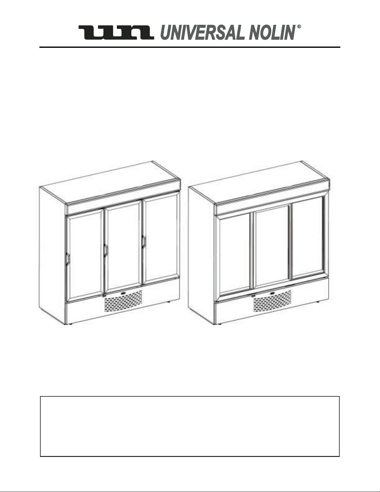
MIRACOOL® GLASS DOOR MERCHANDISER
2000L
IMPORTANT
PLEASE RETAIN FOR YOUR RECORDS
700A Buffington Rd.
Spartanburg, SC 29303
Mailing Address:
PO Box 6650
Spartanburg, SC 29304
Customer Service:
1-800-486-8296
Fax: 864-804-5611
CONTENTS
GENERAL......................................................... 2
UNIT INSPECTION ...........................................2
INSTALLATION ............................................. 2-5
LOCATE UNIT..............................................2
LEVEL .........................................................4
INSTALL SHELVES .....................................5
CONDENSATE DISPOSAL ..........................5
START-UP .....................................................6-7
PRELIMINARY CHECKS..............................6
INITIAL START-UP.......................................7
REFRIGERATION SYSTEM SERVICE ........8-11
COMPONENTS............................................ 8
SERVICE AND TROUBLESHOOTING ....8-11
MAINTENANCE .........................................12-13
LAMP REPLACEMENT ..............................12
CONDENSATE REMOVAL.........................12
CONDENSER/EVAPORATOR ...................12
CABINET EXTERIOR................................. 12
INTERIOR SURFACE.................................12
GENERAL
egaP
These instructions cover the installation, operation,
and maintenance of Universal Nolin MiraCool
series glass-door merchandiser units, size 2000L
®
UNIT INSPECTION
Examine all packages for damage to packaging
material. Damage to external packaging may have
resulted in unit damage. Check packages for all
accessories and components, including legs,
casters, and shelves. File a claim immediately
with the shipping company if shipment is
damaged or incomplete.
INSTALLATION
LOCATE UNIT
Refer to Figure 1 for unit components. Units are
designed for indoor placement only. Provide at
least 3 inches of space between unit cabinet and
any adjacent wall or fixtu
Remove skid base by removing the retaining
screws (8 hex head bolt screws). Refer to Figure
2 to remove the front grille and gain access to skid
retaining screws. If optional casters will be used,
unit must be located on flat, level surface. Refer to
Table 1 for a list of standard parts.
re.
TABLE 1 – STANDARD PARTS
PART FACTORY
INSTALLED
Note: Parts shown are for standard units. Quantity of shelves and clips may vary based on f actory-supplied options.
FIELD INSTALLED QUANTITY
51 X sevlehS
06 X spilC flehS
1 - - launaM noitcurtsnI
4 X teeF gnileveL
4 X spmaL
2
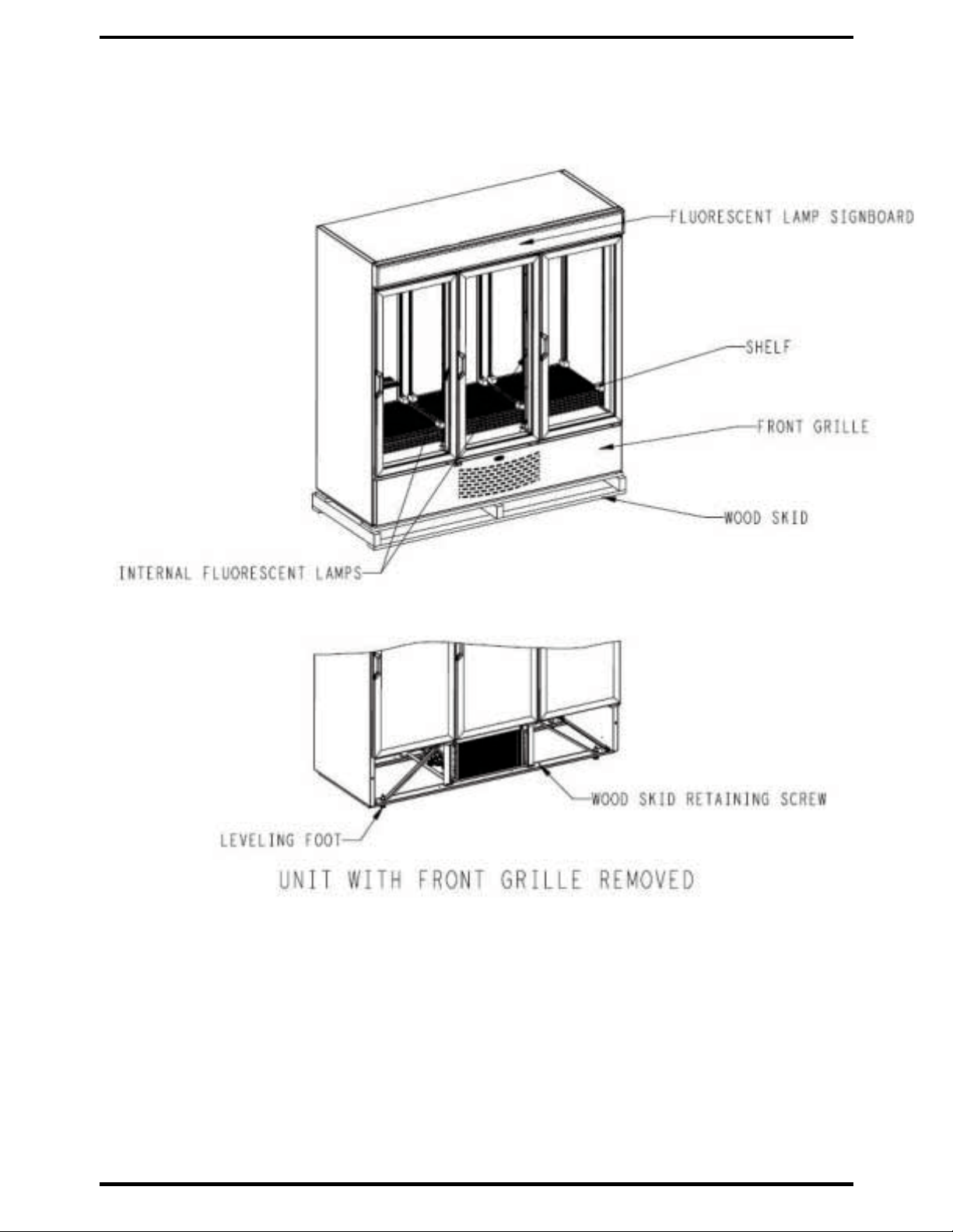
FIGURE 1 - MIRACOOL
®
BOTTLE COOLER UNIT COMPONENTS (MC2000H SHOWN)
3
LEVEL UNIT
To provide adequate condensate drainage and
proper door alignment and operation of unit, the
unit cabinet must be level. Leveling feet are
factory installed. Remove the front grille to gain
access to front and back feet.
TO GAIN ACCESS TO LEVELING
FEET
DANGER
Before servicing unit, disconnect electrical
service. Failure to disconnect electrical service
could result in electrical shock and cause
personal injury or death.
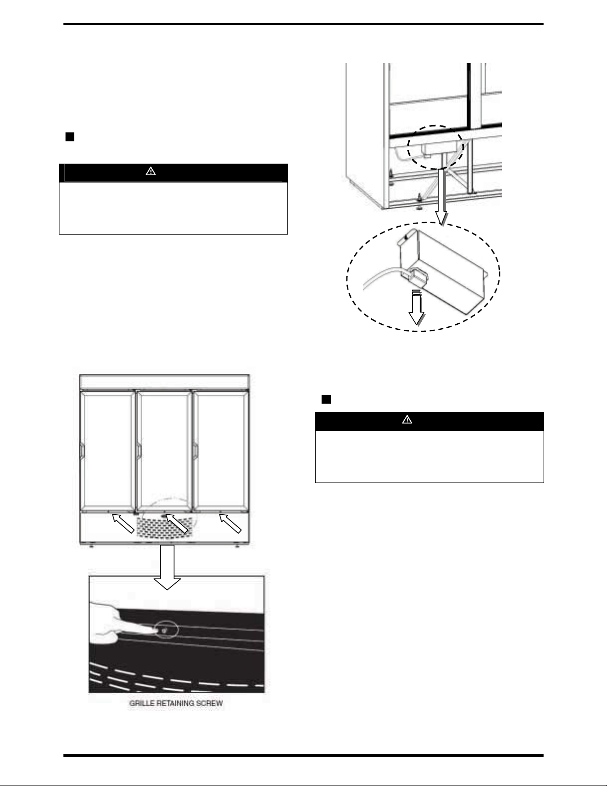
1. After disconnecting the unit from the power
supply, remove the grille retaining screw
located in the upper-most part of the grille.
(See Figure 2)
2. Lift the grille up and away from the unit.
3. Unplug the power supply cord located at the
bottom of the cabinet. (See Figure 3)
FIGURE 3 – DISCONNECT SERVICE CORD
TO LEVEL UNIT
DANGER
Before servicing unit, disconnect electrical
service. Failure to disconnect electrical service
could result in electrical shock and cause
personal injury or death.
Swing Doors- The door is equipped with gravity
assisted cams and will not function properly
without proper leveling of cabinet. Adjust feet
using adjustable wrench so that unit sits
approximately level to floor and doors close
properly. For best door operation, adjust leveling
feet so that cabinet has a
front to back. Optional casters are available to
replace leveling feet.
Sliding Doors- The door will not function properly
without proper leveling of cabinet. Adjust feet
using adjustable wrench so that unit sits
approximately level to floor and doors close
properly.
1/16-in. rake or slant from
FIGURE 2 – REMOVE FRONT GRILLE
NOTE: If casters are not used, local codes may
require cabinet to be sealed around the perimeter
of the cabinet base. Consult local sanitation codes.
Use only sealant material approved for this use,
such as Dow Corning #732.
4
INSTALL SHELVES
Product shelves and a bag containing shelf
support clips are packed inside the unit. Refer to
Table 1 to verify quantity of shelves and shelf
supporting clips. Bottom shelf must be placed on
interior floor and should be inserted into the two
retainer clips provided at the rear corners or the
unit floor.
WARNING
Improper shelf clip installation may cause shelf
and/or product to fall which could result in
personal injury or damage to the unit.
WARNING
Do not overload the shelves. The unit is designed
to use all the shelves provided, installed in
equally spaced configuration. Failure to install
shelves correctly could result in personal injury or
damage to the unit. If fewer shelves or a different
installation configuration is desired, contact the
manufacturer to ensure that shelf overloading will
no occur.
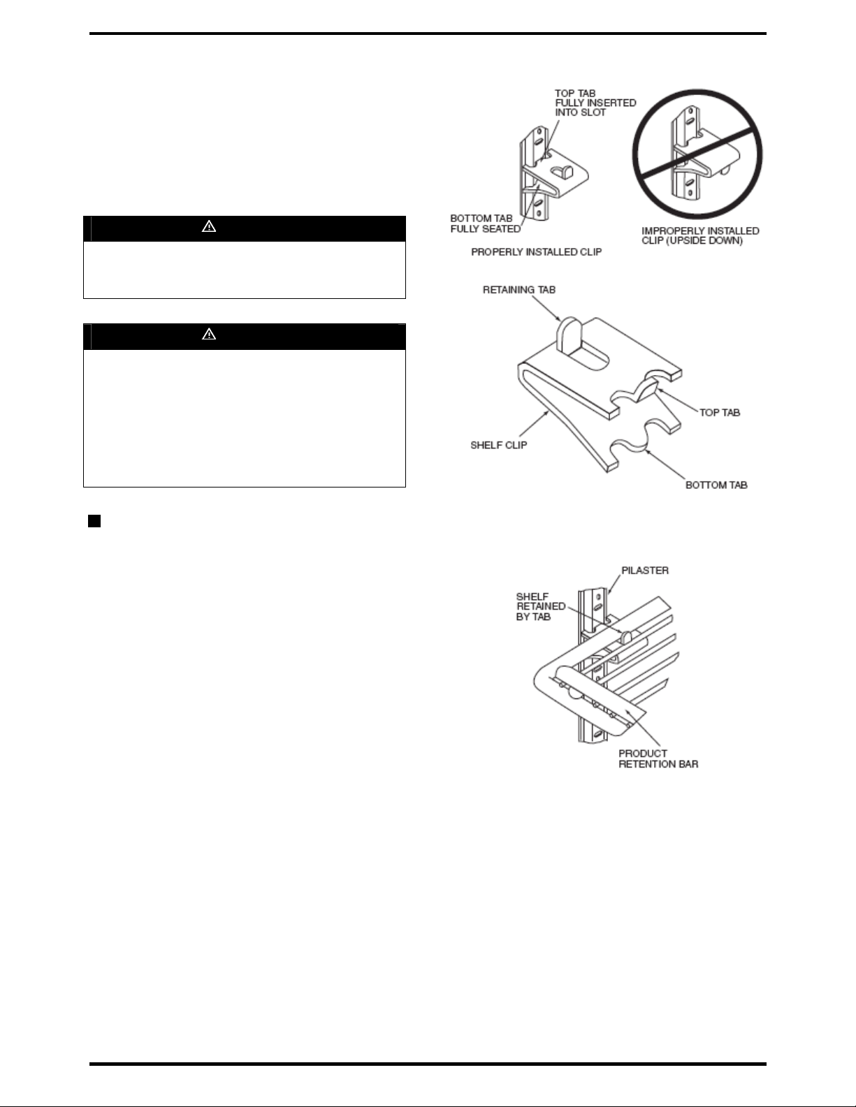
TO INSTALL SHELVES
FIGURE 4 – SHELF CLIP INSTALLATION
1. Determine proper location for shelf clips.
Refer to the numbers on the pilaster to
ensure that all clips are properly located.
2. Insert top tab of the shelf clip into the
desired hole of the pilaster. The retaining
tab should be facing upward as shown in
Figure 4.
3. Rotate the clip downward and insert the
bottom tab into the appropriate hole on the
pilaster. If necessary, squeeze the clip
slightly during installation.
4. Install all remaining clip
above.
5. Install shelves onto clips so that the product
retention bar is facing upward. Be careful
not to dislodge clips during shelf installation.
6. Shelves must be placed so that the retaining
tab on the shelf captures the shelf as shown
in Figure 5.
7. Before loading the shelf, ensure that the
shelf is resting on each of 4 clips and that
the clip are installed as shown in Figures 4
and 5.
s as described
FIGURE 5 – PRO
PER INSTALLATION OF
SHELF ON CLIP
CONDENSATE DISPOSAL
The evaporator drain pan is located in the base of
the product. Airflow in compartment hastens
condensate evaporation so that external drain
plumbing is not required.
5
 Loading...