


R-320
Serial #
Operator’s Manual

WARRANTY
UniVersal Labeling Systems, Inc. warranties all parts to be free from defects in
material and workmanship for a period of one year from the date of shipment
from our facility.
This guarantee is based upon equipment being used 8 hours per day, or 40
hours per week, or in any increment which does not total more than a single
shift operation, or 2,080 hours per year. Warranty will be reduced
proportionally.
This warranty does not cover part failure caused by lack of normal
maintenance, abuse or misuse of the equipment.
PERFORMANCE GUARANTEE
All equipment manufactured by UniVersal Labeling Systems, Inc. carries a 30day performance guarantee. If your machinery does not perform as described
in our quote to you, UniVersal must be notified within 30 days of your
dissatisfaction and we will make every attempt to correct it. If after a
reasonable period of time, the machine does not meet the specified
performance, we will take your machine back and reimburse you in full.

Warranty
Assembly and Operation
Drawings
Layout, Main
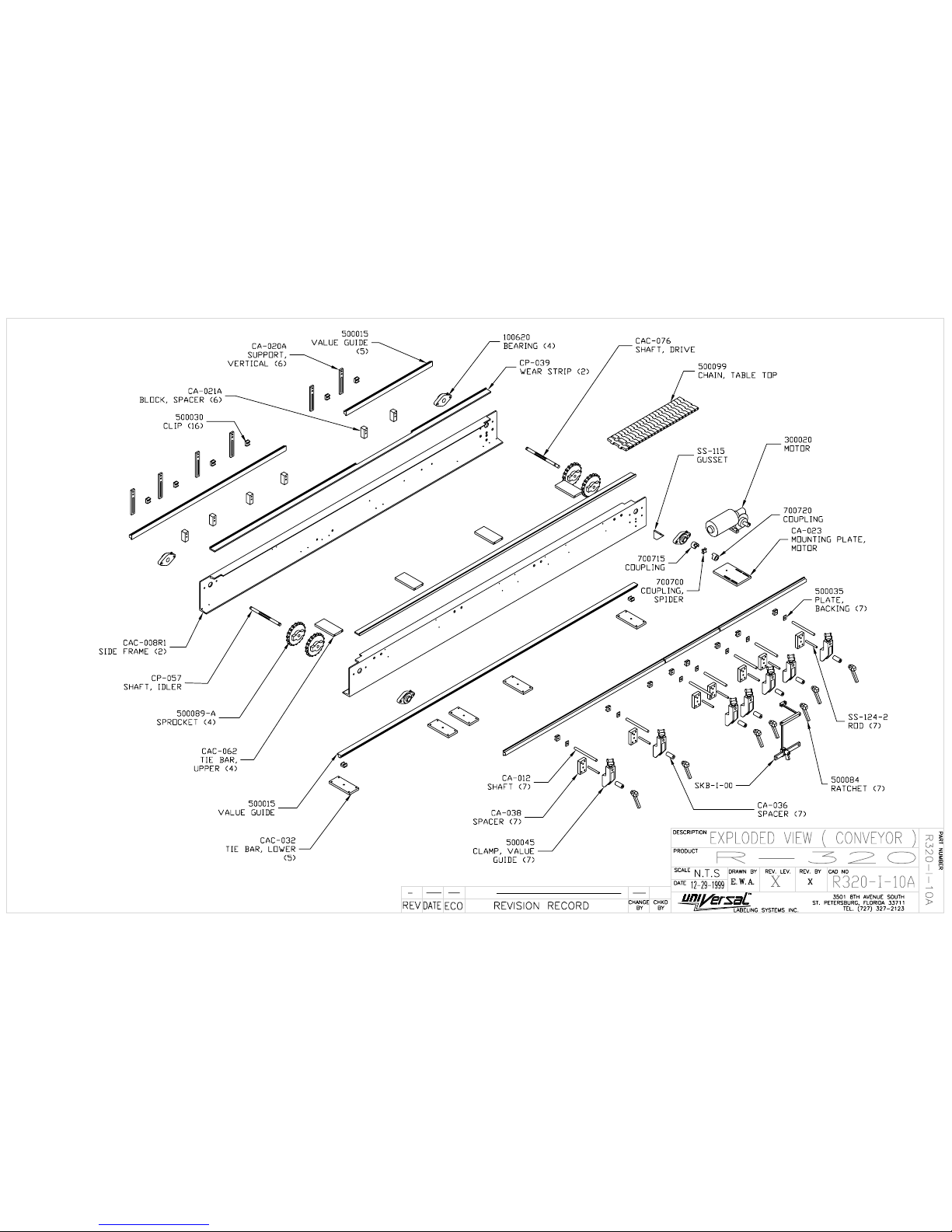
Exploded View (conveyor)
Exploded view BASE Conveyor
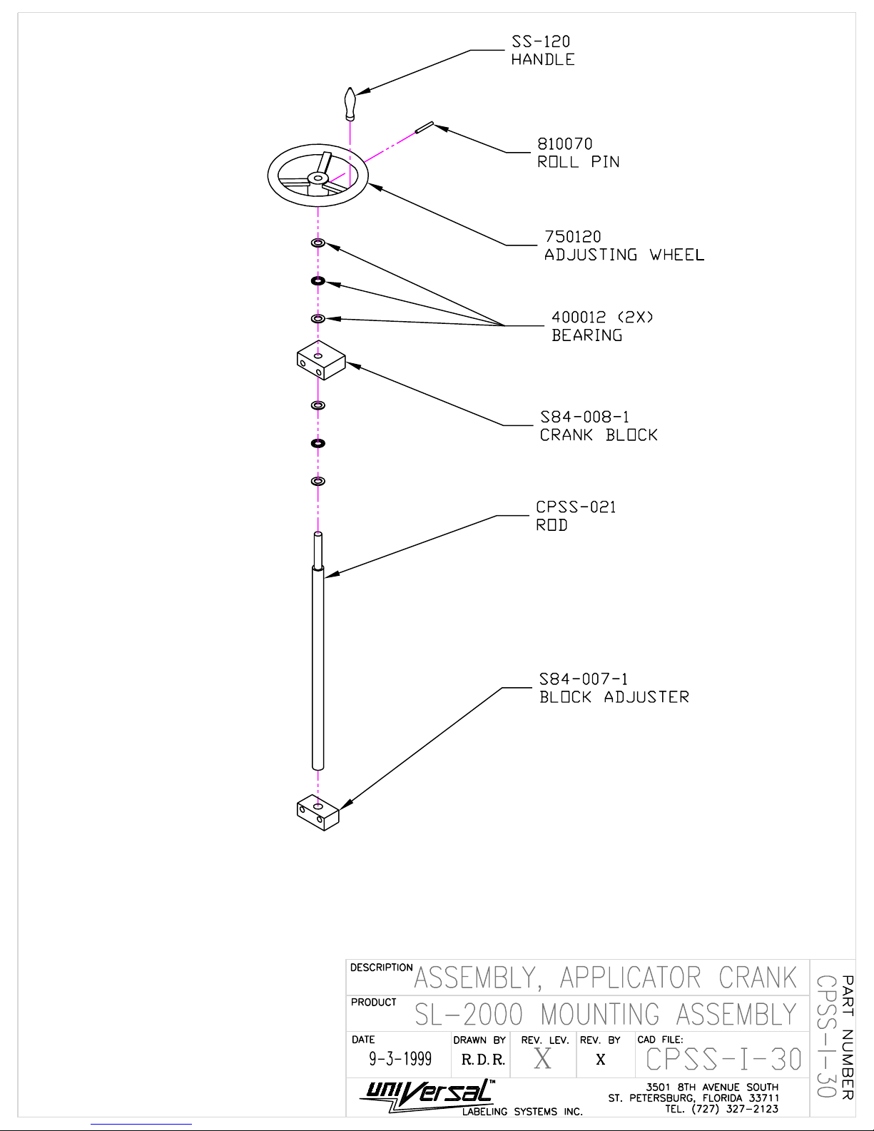
Assembly, Applicator Crank
Micro Adjustor
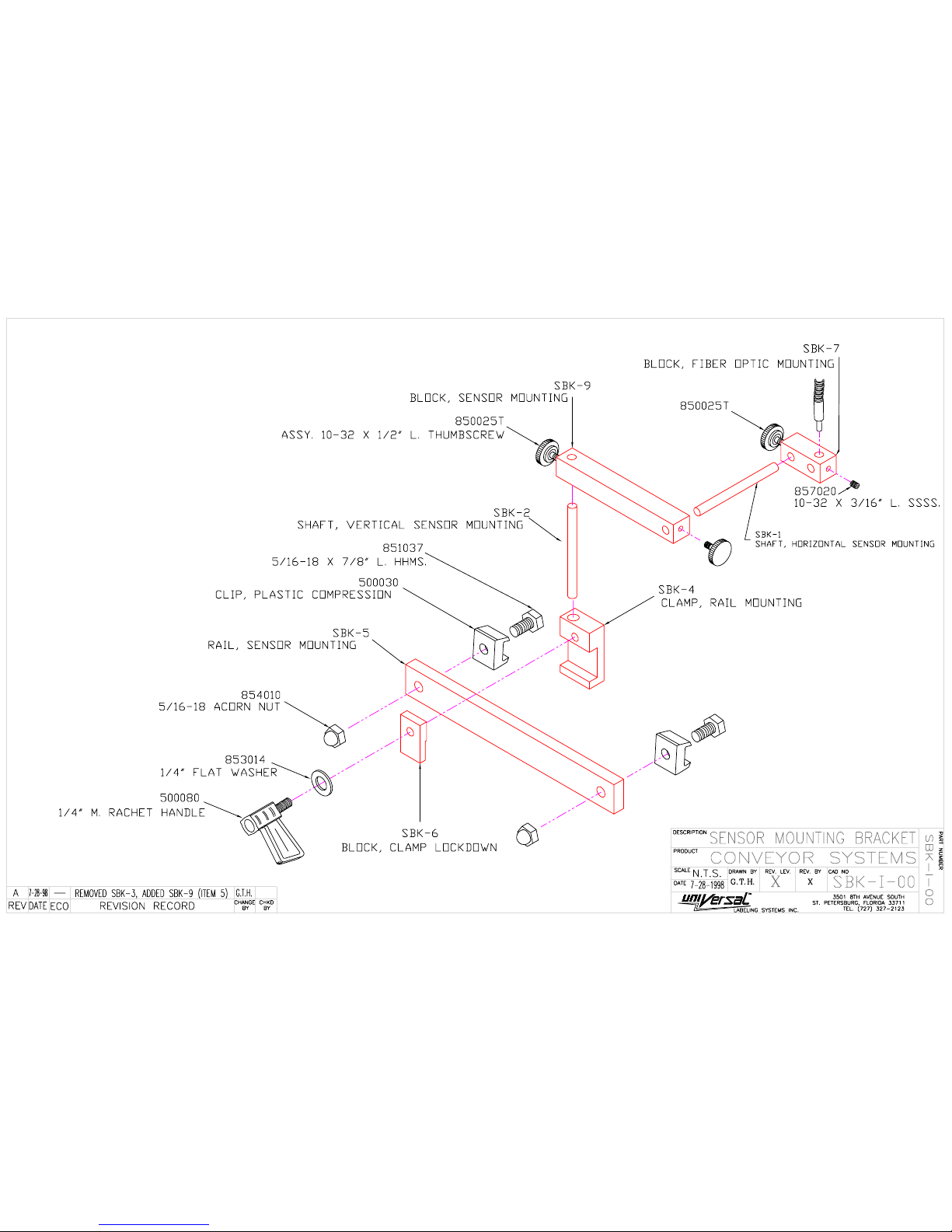
Sensor Mounting Bracket SBK
Wipe Down WPD-500
R320 Elect. Control box
R320 Control Box Electrical Schematic
Product Spacer
Turning Unit BOM
Turning Unit
Mounting Assy CP-1000
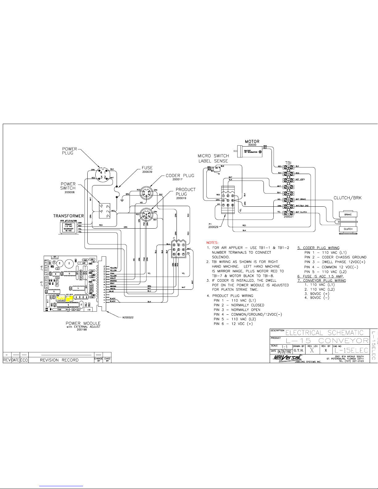
Electrical Schematic L15

MODEL R-320
ASSEMBLY AND OPERATING INSTRUCTIONS
Conveyor Height can be adjusted from your system’s specified height by adjusting the
leveling pads
RE-TIGHTEN LOCKING BOLT AND ANGULAR BRACE, BEFORE REMOVING SUPPORT
AT BOTH ENDS OF CONVEYOR. FAILURE TO RE-TIGHTEN THE LOCKING SCREW
ON SLIDING SLEEVE COULD RESULT IN THE CONVEYOR AND ATTACHMENTS
DROPPING, CAUSING SERIOUS DAMAGE TO THE SYSTEM.
SEE APPLIER INSTRUCTION MANUAL FOR PROPER OPERATION OF APPLIER HEAD
AND WEBBING.
TO ADJUST SYSTEM FOR INDIVIDUAL CONTAINERS, PROCEED AS FOLLOWS:
1. Selecting the container to be labeled, place on conveyor for reference and adjust vertical
height of turning unit so that belt is centered vertically on container.
2. Adjust vertical height of guide rails opposite the applier and turning unit to center on product
but never low enough that rail drags on conveyor top.
3. Adjust guide rail across conveyor so that container is encapsulated securely between
the turning belt and the sponge backing plate. Move container along belt of turning
unit to establish that the sponge backing is adjusted parallel to belt. This is important,
as container must be controlled by turning unit and sponge backing on guide rail.
4. With applier head turned off, turn on conveyor. Set speed control by knob on control box on
front of conveyor to maximum speed.
5. Turn on turning unit by on-off switch located on control box on top of unit. (NOTE:
This unit’s power cord is to be plugged into control box on front of conveyor). Adjust
speed of turning unit so that turning belt is moving at a slightly higher rate of surface
speed than conveyor.
6. Place container on conveyor on entrance end and allow to proceed through turning unit.
7. When it is considered that the container is being properly controlled and guide rail
adjustments are proper, select the appropriate label; place roll on applier and web
properly. Refer to applier instructions.

MODEL R-320
ASSEMBLY AND OPERATING INSTRUCTIONS
8. Stop conveyor by turning speed control to “O”. Turn off turning unit. Plug power
cord of applier into control box on front of conveyor. (NOTE: Applier and turning
unit will not receive power with switch on control box on front of conveyor in OFF
position).
9. Raise or lower applier so that label is centered on container. Label web must always
run to lower edge of peeler bar on this system, with edge of peeler bar clearing top of
conveyor EDGE. DO NOT LOWER APPLIER TO THE POINT WHERE EDGE
OF PEELER BAR IS RESTING ON TOP OF CONVEYOR EDGE.
10. Adjust peeler bar so that back side clears turning belt by no more than 1/8”.
11. Turn on master switch on applier, then turn on motor switch; one label will advance.
12. Product sensing micro switch is secured to edge of guide rail with arm extending
through guide rail. Activating this switch by hand will cause applier to deliver a label.
NOTE: Position label at end of peeler bar and adjust star wheel on applier so that 1/8”
to 1/4” of label is extending beyond peeler bar edge when label is delivered and
applier stops delivering a label. Trigger applier head with product sensing several
times to allow web to track properly and to observe extension of label beyond peeler
bar.
YOU SHOULD NOW BE READY TO LABEL
Turn on conveyor by speed control knob and adjust to just below maximum speed. Turn on
turning unit. Speed control knob on applier should be set at approximately 65 on dial - - with
turning unit at approximately the same setting.
With all systems running - - Place container on conveyor and
NOTE:
1. Point at which product switch activates relative to position of container. The ideal
point of which the applier starts delivering the label is as the container contacts the
center line of the first pulley of the turning unit and is encapsulated between the
turning unit belt and the rubber of the guide rail. Adjust the product sensing switch
back or forward to achieve the best results. A little experimenting by the operator for
the optimum position is in order. Triggering the applier too early or too late can result
in mis-register or wrinkled labels.
2. Next in this procedure, observe that as the label is being dispensed and applied that the
speed of the applier is not causing the label to be pulled by being too slow. (Speed up
by speed control on applier), or is delivering the label too fast as to incur wrinkling of
label on the container (slow applier by same procedure).

MODEL R-320
ASSEMBLY AND OPERATING INSTRUCTIONS
IT IS EXTREMELY IMPORTANT THAT SPEEDS OF LABEL DELIVERY AND PRODUCT
BE MATCHED FOR SATISFACTORY PLACEMENT AND WIPE DOWN OF LABEL.
If label is tending to walk up or down on container, label applier may be rotated to position peeler
bar in parallel with container, so that label is started on container accurately, by loosening large
hex nut on swiveling bracket that applier is secured to and located on sliding sleeve on post.
Rotate applier by turning knurled knob at swivel point. NOTE: In making this adjustment, be
sure that rotating the applier does not cause the peeler bar to be forced into contact with top of
conveyor. Raise applier to prevent this, then lower into position after adjustment is made. Retest by passing one container through the system and noting the label placement. If still off, readjust as above until the optimum position is found.
It has been noted many times that during a labeling run that label placement may vary slightly.
This is most often the result of non-uniformity in the containers.
1. Slight tapers from top to bottom in the containers not visible to the eye.
2. Bottoms and sides of the containers not square, again not detectable visually.
Variations in containers as small as .005 inch can result in visual mis-alignment when wrapping
labels completely around containers. Most often these discrepancies are attributed to the abetting
system and are pointed out in these instruction as GUIDE LINES in TROUBLE SHOOTING the
equipment.
Suggestions for improvements in the design of our equipment is solicited and appreciated.
Many thanks for reading these instructions in their entirety.

SUGGESTED SPEED SETTING
As tested at the factory, the following are suggested setting of speeds and time delays:
DIAL SETTING
* Conveyor Speed _______________
* Turning Unit _______________
* Applier _______________
Product Spacer _______________
These settings will product approximately _______________
parts per minute production
If speed of any of the above “*” are changed for any reason, comparable changes in the other
settings should be made.
The above speed settings are provided only as guidelines for start-up and may need to be changed
because of variables in voltages, area to area, and other variables over which we have no control.
SETUP INSTRUCTIONS

When machine is received, open carton carefully and remove machine by placing hands under
machine base for lifting. Place machine on flat surface for installation of label roll holder to
machine. (NOTE: Acorn nuts and hex nuts to be removed). Slide label reel over the two
threaded studs, secure with hex nuts, then install the two acorn nuts. Machine is not ready for
installation and can be secured to an appropriately fabricated bars, flatplate, etc., by the four (4)
bolts on the bottom of machine that are securing the bottom cover for shipment.
FOR THOSE MACHINES EQUIPPED WITH LOW LEVEL ALARM AND/OR WEB
BREAK ALARM:
NOTE: Low level alarm is mounted to label reel bar and needs only to be plugged into small 2
prong plug dangling from rear of machine. Swinging curved bar is to be moved downward for
loading of labels and rests on outside of roll when in operation, under slight spring pressure.
When position of curved bar reaches a position near core of label roll, an audible sound will emit
from small box mounted to top of machine. Light will also come on at same time. Both audible
alarm and light may be cut off by toggle switch on top of box.
NOTE: Web break alarm - - located between the pull roll and web rewind. Waste web must
pass under plastic finger. The finger is supported by waste web and in the event of web breakage,
finger will drop downward causing audible signal and light to come on top of box on top of
machine.
SEE WIRING DIAGRAM IN BACK OF MANUAL


R320 AUTOMATIC SYSTEM
WITH L15H APPLICATOR
RECOMMENDED SPARE PARTS
PART # PART DESCRIPTION
200109 MICRO SWITCH, LABEL SENSING
200198 POWER MODULE
420173 STARWHEEL SPRING
L-129-S STARWHEEL, LABEL SENSING
L-137-H DRIVE ROLLER (HD)
L-140-F-3 SLIP CLUTCH COLLAR (REPLACES L-140-F-2)
L-175-1 ASSY. SPROCKET W/FELT & BEARINGS
L-143 LOWER IDLER ROLL ASSY (KNURLED ALUMINUM)
L-176-1 DRIVE BELT (120 X L037)
200160 TRANSFORMER
300013 REPLACEMENT MOTOR BRUSH FOR L-15H
300023 REPLACEMENT MOTOR BRUSH FOR TURNING UNIT
600008 4” TURNING UNIT BELT
600007 2” TURNING UNIT BELT
TA-215 2”W.x15”L. FOAM PAD W/PLATE
TA-415 4”W.x15”L. FOAM PAD W/PLATE
500030 PLASTIC COMPRESSION CLIP FOR CONVEYOR RAILING
L-132 IDLER ASSY (FOR L-15H)
LP-100-S-1-X ASSY, INTERMEDIATE SPROCKET
410000 CHAIN FOR L-15H (19.25”)
L-128-C REWIND SPOOL CLAMP FOR L-15
L-105-RA ASSY, WEB GUIDE CLAMP (R.H.)
L-105-LA ASSY, WEB GUIDE CLAMP (L.H.)
600300 1” PEELER PLATE TAPE (50’ ROLL)
200046 FUSE FOR CONTROL BOX (10 AMP)
500085 3/8 RATCHET HANDLE


TA-2/4 2 & 4 INCH TURNING UNITS
Bill of Material
ID# PART# QTY DESCRIPTION
1 300022 1 MOTOR, (1/4 HP. 100 RPM.)
2 400016 4 BEARING, (SEALED 3/8” 99R6)
3 410000 1 CHAIN, (# 25 LINK 19.375”)
4 410001 1 LINK, (# 25 MASTER)
5 600007 1 BELT, (2" X 37-1/4” 2" TA)
** 600008 1 BELT, (4" X 37-1/4” 4" TA)
7 TA-2-202 1 FRAME, MAIN
8 TA-2-203 2 POST, MOUNTING
9 TA-2-205 2 BLOCK, BEARING
10 TA-2-205-A 1 PLATE, IDLER ROLLER MOUNTING
11 TA-2-205-B 1 PLATE, UPPER BEARING MOUNTING
15 TA-2-219-1 1 COVER, MOTOR SHAFT
16 TA-2-201 1 PLATE, MOTOR BASE
** TA-4-401 1 PLATE, MOTOR BASE
17 TA-2-217 1 PLATE, CONVEYOR BELT BACKING
** TA-4-403 1 PLATE, CONVEYOR BELT BACKING
18 TA-4-406-1 1 COVER, TA CHAIN GUARD (1 OF 2)
19 TA-4-406-1 1 COVER, TA CHAIN GUARD (2 OF 2)
20 TA-4-407 1 SUPPORT, CHAIN GUARD
21 TA-2-206-A 1 SHAFT, IDLER ROLLER
** TA-4-408A 1 SHAFT, IDLER ROLLER
22 TA-2-206-B 1 SHAFT, DRIVE ROLLER
** TA-4-408B 1 SHAFT, DRIVE ROLLER
23 TA-2-204-A 1 ROLLER, IDLER 2” WIDE
** TA-4-409A 1 ROLLER, IDLER
24 TA-2-204-B 1 ROLLER, DRIVE 2” WIDE
** TA-4-409B 1 ROLLER, DRIVE
25 TA-4-413-1 1 SPROCKET, MOTOR
26 TA-4-412 1 SPROCKET, DRIVE
27 TA-2-218 1 PLATE, 2" COVER
** TA-4-418 1 PLATE, 4” COVER
28 L-172-04 2 SPACER, .125
29 L-172-03 OR L-172-12 3 SPACER, (.062 OR .093 RESPECTIVELY)
30 FLOOR STOCK 4 ACORN NUT, 1/4-20
31 FLOOR STOCK 4 1/4-20 x 1" H.H.M.S.
32 FLOOR STOCK 2 8-32 x 3/4" S.H.C.S.
33 FLOOR STOCK 17 10-32 x 3/4" S.H.C.S.
34 FLOOR STOCK 3 10-32 x 1/2" S.H.C.S.
35 FLOOR STOCK 2 8-32 x 3/8" SOCKET SET SCREWS
36 FLOOR STOCK 4 1/4-20 x 5/8" F.H.M.S.
37 FLOOR STOCK 4 6-32 x 3/8" S.H.C.S.
38 FLOOR STOCK 2 1/4-20 x 1/4" SOCKET SET SCREWS
39 FLOOR STOCK 2 10-32 x 1/4" SOCKET SET SCREWS
40 FLOOR STOCK 2 8-32 x 1" S.H.C.S.
41 FLOOR STOCK 2 8-32 HEX NUT
42 FLOOR STOCK 1 1/4-20 x 1/2" SET SCREW
43 FLOOR STOCK 2 8-32 x 3/8" S.H.C.S.
FILE: G:\ACCESSORIES\TA\TA2&4.DOC Revised 10:56 AM March 9, 2000

TA-2/4 2 & 4 INCH TURNING UNITS
Bill of Material
ID# PART# QTY DESCRIPTION
44 TA-2-215B 4 GUIDE, BACK PLATE
45 SS-112 2 KNOB, MICROMETE R ADJ.
46 TA-2-215A 2 PLATE, TURN-AROUND MOUNT
47 FLOOR STOCK 2 BOLT, 3/8 x 2-1/4 H.H.M.S
48 FLOOR STOCK 11 WASHER, #10 x .06 THK.
49 FLOOR STOCK 4 WASHER, 1/4” x .06 THK.
50 FLOOR STOCK 4 WASHER, #6
51 200026 1 CONNECTOR, 4 PIN MALE (CONVEYOR MODEL)
52 TB-1 1 ASSEMBLY, TA BOX (FIELD UPGRADE MODEL)
N/S 300023 2 BRUSHES, FOR MOTOR 300022
(**) = SPECIFICALLY FOR 4” TURNING UNIT (TA-4)
FILE: G:\ACCESSORIES\TA\TA2&4.DOC Revised 10:56 AM March 9, 2000

 Loading...