

Universal Flow Monitors (UFM) CP-N6 Operating Manual
CoolPoint
®
Installation and Operation Manual
Vortex Shedding Flowmeters
Series:
CP/N6- CP/N16
Effective with products having serial number 090100001 and greater
UNIVERSAL FLOW MONITORS, INC.
1755 East Nine Mile Road PO Box 249
Hazel Park, MI 48030-0249
TEL (248) 542-9635 FAX (248) 398-4274
Website: http://www.flowmeters.com
CPMED061010

UNIVERSAL FLOW MONITORS, INC.
TABLE OF CONTENTS
CONTENTS
TABLE OF CONTENTS....................................................................................................................................... 2
PROPRIETARY NOTICE .................................................................................................................................. 3
USING THIS MANUAL ...................................................................................................................................... 3
QUICK SET UP ............................................................................................................................................................ 4
WIRING DIAGRAMS (Pin Configurations)...................................................................................................... 6
INSTALLATION ..................................................................................................................................................... 7
GENERAL SPECIFICATIONS ....................................................................................................................... 8
OPERATION ......................................................................................................................................................... 10
APPLICATIONS ................................................................................................................................................. 10
MODEL CODES........................................................................................................................................................ 10
PRESSURE DROP CHARTS ................................................................................................................................. 11
CABLing ..................................................................................................................................................................... 11
DIMENSIONS ........................................................................................................................................................... 12
RMA NOTICE RETURN MERCHANDISE AUTHORIZATION ............................................................ 13
RMA FORM ............................................................................................................................................................ 15
WARRANTY INFORMATION .................................................................................................................... 16
2 CPMED061010
UNIVERSAL FLOW MONITORS, INC.
PROPRIETARY NOTICE
The information contained in this publication is derived in part from proprietary and patented data
and has been prepared for the express purpose of assisting in installation, operation, and
maintenance of the instruments described herein. Publication of this information does not convey
any rights of use or reproduction other than in connection with the installation, operation and
maintenance of the equipment described herein. Universal Flow Monitors, Inc. reserves the right
to change the information contained in this publication at any time and without prior notice.
USING THIS MANUAL
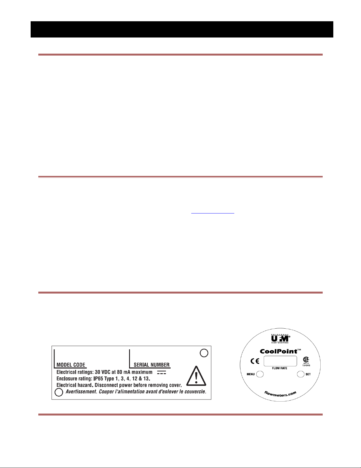
In order to use this manual, you will need the model code that can be found on the nameplate of
the flowmeter, as shown on the example below (see MODEL CODES). The Model Code allows you
to determine minimum and maximum flow capabilities, as well as pressure drop for various sizes.
NAMEPLATE EXAMPLE – CP/N6-CP/N16
3 CPMED061010

UNIVERSAL FLOW MONITORS, INC.
Install in pipe making sure to orient IN port to flow supply.
10 pipe diameters distance is required upstream and 5 down for best accuracy.
Use proportional spacing if this much space is not available.
50 pipe diameters are required upstream as distance from a valve.
No use of Teflon tape please. (See detailed piping instructions.)
Attach pin connector/cable assembly to unit. (See detailed wiring instructions.)
CONFIGURATION OF METER
At start up , display shows 888 showing that it’s digits are all functional
8.8.8
Next firmware revision is displayed.
Then model is shown
4.69
Cn
Example
Run mode achieved. Flow rate displayed at 0 flow is 0.
0.00
Note that if no adjustments are made, GPM displays, alarm is off and output is 4-20 mA.
SELECTING LPM OR GPM
If flow is started, toggle from LPM to GPM using Set button. LPM will be the higher value.
12.4
Example
OPTING FOR AND SELECTING ALARM POINT
Depress Menu for 1 second.
This will display ALA for alarm mode
ALA
If pulse mode is showing, push Menu button to get back to alarm mode.
PUL
PIPING
QUICK SET UP
4 CPMED061010

UNIVERSAL FLOW MONITORS, INC.
Push Set button and default setting of zero will display (indicating that alarm is not active)
00.0
Depress Menu button repeatedly until desired set point is achieved.
12.6
Depress Set button to save the setting
12.6
Settings roll over to zero and start over if you miss it the first time. Only displayed values are feasible.
Now display shows “nc “indicating that circuit is closed when not in alarm state.
nc
Depress Menu button to change this to “no” indicating that circuit is open when not in alarm state.
no
Depress Set button to save the setting
SELECTING PULSE OUT INSTEAD OF ALARM
Depress Menu for 1 second.
This will display ALA for alarm mode
ALA
Push Menu button to change to pulse mode.
PUL
Depress Set button to save the setting
Note that pulse out is at a predetermined rate of pulses per gallon and is not altered by LPM display.
4-20 mA output is not affected by pulse out.
5 CPMED061010
UNIVERSAL FLOW MONITORS, INC.
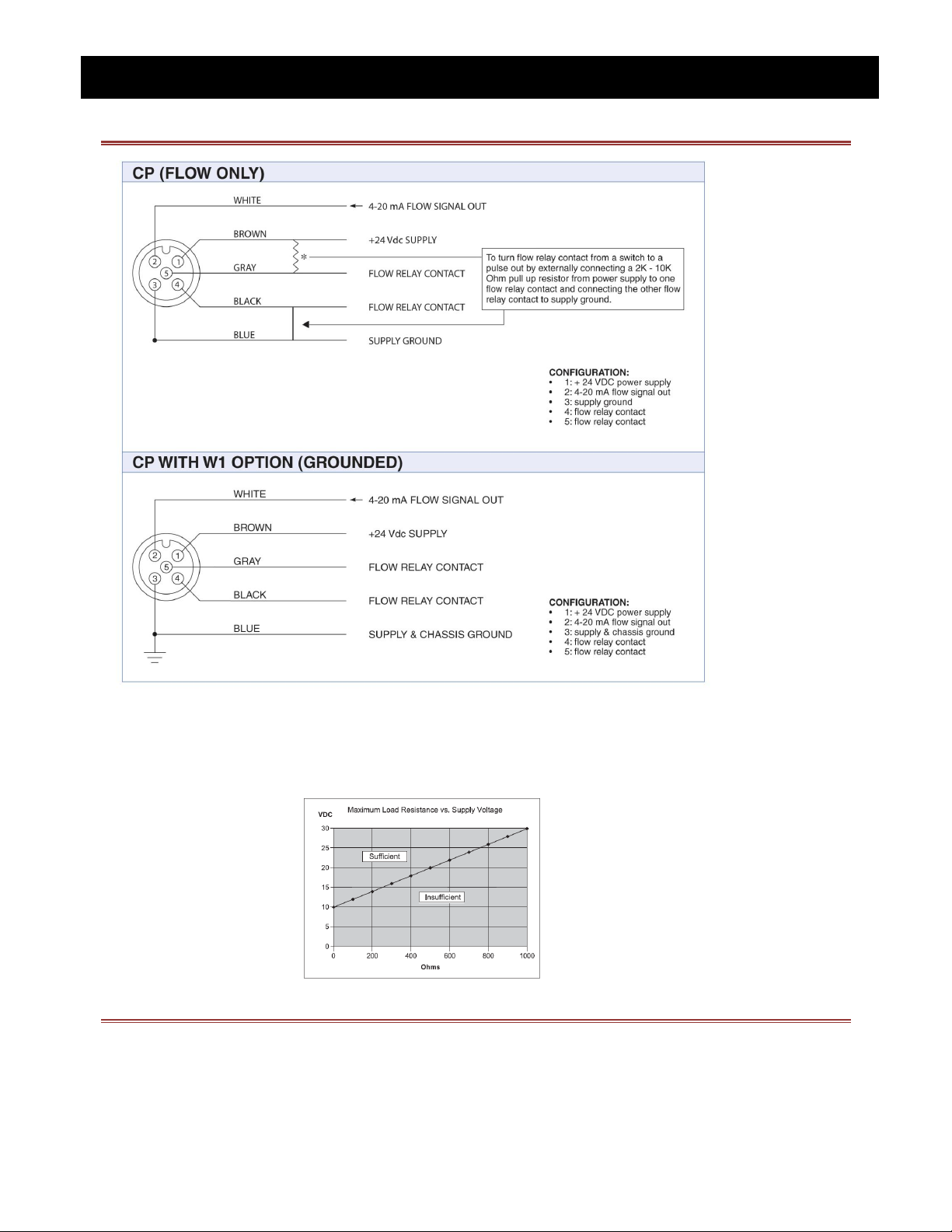
WIRING DIAGRAMS (PIN CONFIGURATIONS)
DC Power Supply Voltage Requirements for 4-20 mA Outputs:
6 CPMED061010
 Loading...