

Page 1
1-800-547-5740 • Fax: (503) 643-6322
www.ueitest.com • email: info@ueitest.com
UTL2002
INSTRUCTION MANUAL
Page 2
I n s t a l l a t i o n
1. Pull apart the two halves of the case by inserting a coin in the slot on
the bottom of the case and tw i s t .
2. Feed the sensor’s wires (the end with bare wires) through the top
hole in the side of the black case and connect the wires into the
wiring terminals. No polarity on the wiring is required.
3. Connect on 9V-006P battery and fit it in place.
4. Replace two halves of the case properly.
5. To mount the case on the wall:
A. Drill two holes 50mm apart, ensuring holes are aligned
vertically.
B. Fit wallplugs and screws, but allow screws to protrude from
the wall by 3mm.
C. Place keyholes on back of the case over screws and push
down to mount.
D. If using a mains adapter instead of battery, connect to the
socket for mains adapter at the right side of the back case.
The system is now ready for use.
Operating Instructions
For Bath-Tub
1. Mount the unit over the bath-tub.
2. Adjust your desired water level (fix the sensor by pressing the
suction cap)
3. The alarm will be triggered when water is over the sensor.
For Floor
1. Take away the suction cap from the sensor.
2. Place the sensor on the flat floor.
3. The alarm will be triggered when water floods.
Testing the Battery
Test the battery condition by pressing the “Test Button”.
M a i n t e n a n c e
Cleaning and Decontamination
Periodically clean your instrument’s case using a damp cloth. DO NOT
use abrasives, cleaning solvents or strong detergents, as they may
damage the finish or affect the reliability of the structural components.
Battery
Check the battery every 2 months visually to ensure no leaks have
occurred. Leaking battery will result in poor performance and could
damage the unit.
Introduction
The UTL2002 sounds an alarm when water contacts its remote sensor. Use
it in freezers, refrigeration condensate pans, water heater containment
pans, basements, marine applications, RV’s and much more.
Features include
• 9 Volt battery operated
• Jack for conventional 9 Volt adapter
• Remote sensor with 7” cord
• Larger remote-sensor cord is easily added
• Suction-cup mounted sensor
• Visual (LED) and loud audible alarms
• Self test button
• Mounting hardware included
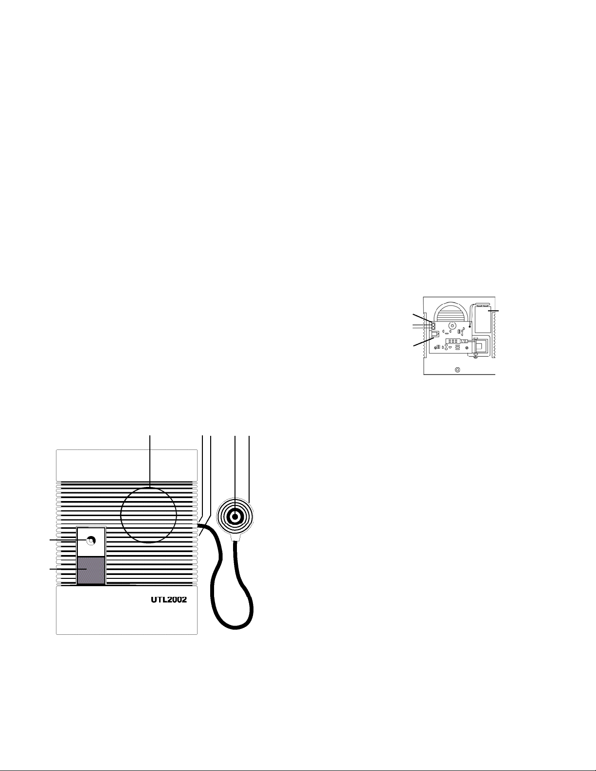
C o n t rols and Indicators
1. L ED Indica t o r
2. Test Button
3. Speaker
4. Hole for Sensor Wires
5. Socket for Mains Adapter
6. Open Slot
7. Sensor
8. Suction Cap
UTL2002-MAN P. 1
1
2
3
4 5
6 7
On the back
of sensor
Battery
Compartment
9V
Battery
Wiring Terminal
Sensor’s Wires
Socket for
Mains Adapter
Page 3

Limited Warranty
The UTL2002 is warranted to be free from defects in materials and workmanship for a period
of one year from the date of purchase. If within the warra n ty period your instrument should
become inoperative from such defects, the unit will be repaired or replaced at UEi’s option.
This warra n ty covers normal use and does not cover damage which occurs in shipment or
failure which results from alteration, tampering, accident, misuse, abuse, neglect or improper
maintenance. Batteries and consequential damage resulting from failed batteries are not
covered by warra n ty.
Any implied warranties, including but not limited to implied warranties of merchantability
and fitness for a particular purpose, are limited to the express warranty. UEi shall not be
liable for loss of use of the instrument or other incidental or consequential damages,
expenses, or economic loss, or for any claim or claims for such damage, expenses or
economic loss. A purchase receipt or other proof of original purchase date will be required
before warra n ty repairs will be rendered. Instruments out of warra n ty will be repaired (when
r e p a i r able) for a service charge. Return the unit postage paid and insured to:
1-800-547-5740 • FAX: (503) 643-6322
www.ueitest.com • Email: info@ueitest.com
UTL is distributed by UEi
This warranty gives you specific legal rights. You may also have other rights which vary from
state to state.
UTL2002
Water Leakage Indicator
Copyright © 2007 UEi UTL2002-MAN 4/07
PLEASE
RECYCLE
 Loading...