

1-800-547-5740 • Fax: (503) 643-6322
www.ueitest.com • email: info@ueitest.com
UET175
INSTRUCTION MANUAL
Checking Transformer
1. Turn off power.
2. Locate the leads to be tested.
3. S e p a r ate the remaining leads in the primary so they do not
short out.
4. Obtain an AC volt meter or multi-tester than can measure at
least 30 volts.
5. Apply the correct voltage to the primary side of the transformer.
6. With the AC volt meter, measure the voltage across the
secondary leads using the following table.
NOTE: No-load voltage reading may be slightly higher than the above
stated voltages.
7. If incorrect readings are measured, immediately disconnect the
voltage to the primary and recheck all connections.
8. Check the fuse in line with the blue lead in the secondary making
sure it is good. If not, replace only with a 3.15 Amp/250 Volt
slow blow fuse.
9. Reapply the voltage to the primary. If incorrect readings continue
to be measured, obtain a new transformer.
10. If correct readings are measured, disconnect power to the
primary and proceed to install the transformer.
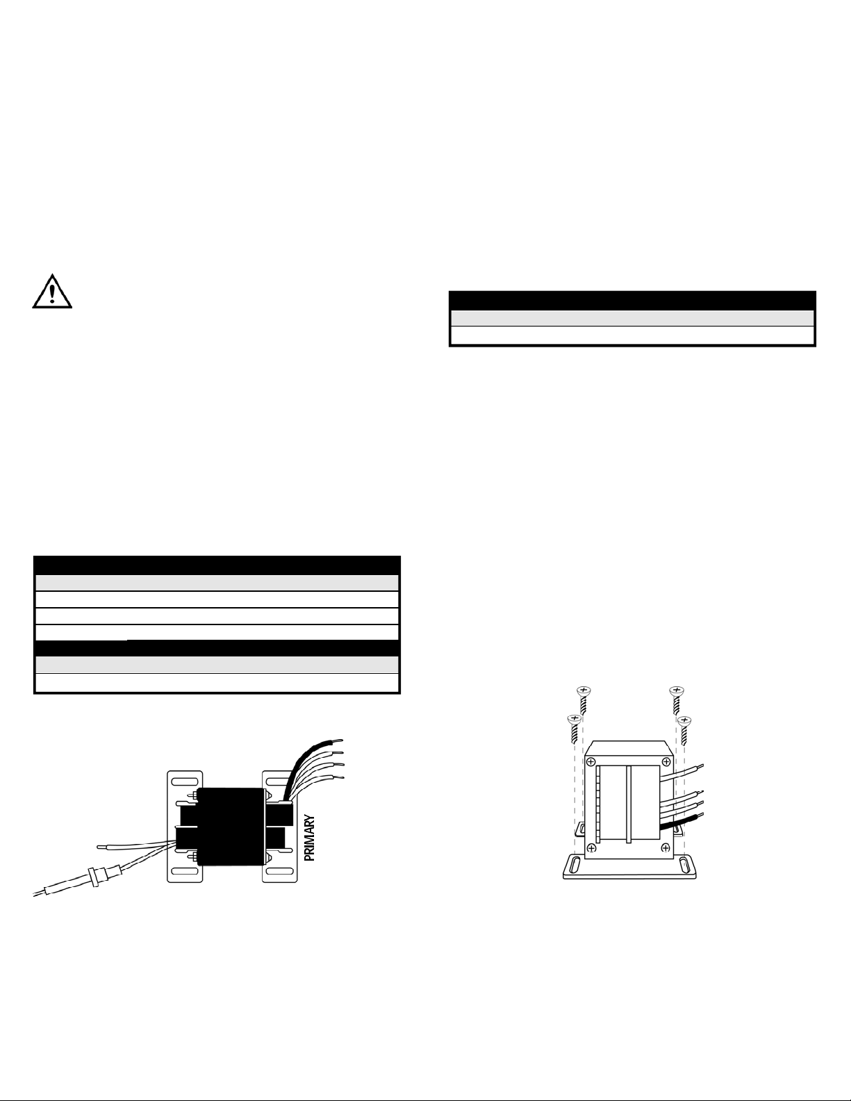
Mounting
The UET175 is designed for foot mounting. Four mounting screws are
provided (Fig 2).
Introduction
The UET 175 is used for 24V control circuits to protect equipment or
minimize shock hazard. Rating not to exceed 75 VA .
Features include
• Primary and secondary wires are color coded for easy hookup
• Includes: Fuse, 6 wire nuts, and 4 mounting screws
Safety Notes
CAUTION!
1. Transformer should be installed by a trained, experienced
serviceman.
2. Power should be disconnected before beginning installation
to prevent electrical shock or equipment damage.
3. Wiring must comply with local codes and ordinances.
4. All unused exposed leadwires should be taped or insulated.
5. Check thoroughly after installing.
Operating Instructions
Application
Wire color codes - The UET175 has color coded wires to make hook-up
as simple as possible (Fig 1).
UET175-MAN P. 1
Primary (Input)
AC Voltage Use Lead Color
120 volts White and Black
208 volts White and Red
240 volts White and Orange
Secondary (Input)
AC Voltage Use Lead Color
24 volts Yellow and Blue
Secondary Voltage
Use leads Voltage
Yellow and Blue 24 Volts
(Fig 2)
(Fig 1)
Yellow
Fuse
Blue
White
Black
Red
Orange

Installation
1. Power must be disconnected before installing the transformer. It
is imperative that wiring conform to local codes and ordinances.
2. Follow hook-up procedure.
24V Secondary (yellow and blue leads)
a. Make sure power is OFF
b. Determine primary voltage (120, 208, 240) and locate correct leads
c. Tape the ends of the remaining leads in the primary to prevent them
from shorting out
d. Install transformer observing correct primary and secondary connections
e. Apply power and check correct operation
Standard & Optional Accessories
Standard
Fuse, pkg. of 3 (3. 15A, 250V slow blow) . . . . . . . . . . . . . . . . . .AF90
UET175-MAN P. 2

Limited Warranty
The UET 175 is warranted to be free from defects in materials and workmanship for a period of
one year from the date of purchase. If within the warra n ty period your instrument should
become inoperative from such defects, the unit will be repaired or replaced at UEi’s option.
This warra n ty covers normal use and does not cover damage which occurs in shipment or
failure which results from alteration, tampering, accident, misuse, abuse, neglect or improper
maintenance. Batteries and consequential damage resulting from failed batteries are not
covered by warra n ty.
Any implied warranties, including but not limited to implied warranties of merchantability
and fitness for a particular purpose, are limited to the express warranty. UEi shall not be
liable for loss of use of the instrument or other incidental or consequential damages,
expenses, or economic loss, or for any claim or claims for such damage, expenses or
economic loss. A purchase receipt or other proof of original purchase date will be required
before warra n ty repairs will be rendered. Instruments out of warra n ty will be repaired (when
r e p a i r able) for a service charge. Return the unit postage paid and insured to:
1-800-547-5740 • FAX: (503) 643-6322
www.ueitest.com • Email: info@ueitest.com
This warranty gives you specific legal rights. You may also have other rights which vary from
state to state.
UET175
Foot Mount Multi-Tap Transformer
Copyright © 2007 UEi UET175-MAN 1/07
PLEASE
RECYCLE
 Loading...