

Page 1
UAD P
OFTWARE
S
Manual version 140211
ERSION
V
LUG
7.5
-I
NS
M
ANUAL
Universal Audio, Inc.
4585 Scotts Valley Drive
Scotts Valley, CA 95066-4517
www.uaudio.com
Customer Support
USA (toll-free): 1-877-698-2834
International: +1-831-440-1176
Page 2

N
OTICES
Disclaimer
This manual provides general information, preparation
for use, installation and operating instructions for the Universal Audio UAD Powered Plug-Ins. The information contained in this manual is subject to change without notice.
Universal Audio, Inc. makes no warranties of any kind
with regard to this manual, or the product(s) it refers to,
including, but not limited to, the implied warranties of
merchantability and fitness for a particular purpose.
Universal Audio, Inc. shall not be liable for errors contained herein or direct, indirect, special, incidental, or
consequential damages in connection with the furnishing, performance, or use of this material or the product(s).
Copyright
Copyright ©2014 Universal Audio, Inc. All rights reserved.
Trademarks
Universal Audio, the Universal Audio diamond logo,
UAD, UAD Series, UAD-1, UAD-2, UAD-2 SOLO, UAD-2
DUO, UAD-2 QUAD, UAD-2 OCTO, Powered Plug-Ins,
1176LN, 1176SE, Teletronix, LA-2A, LA-3A, LA-610, LA610MkII, 2-1176, 610, 2-610, 6176, 710 Twin-Finity,
2192, 4-710d, Cambridge EQ, DreamVerb, Plate 140,
Precision Limiter, RealVerb Pro, Precision Buss Compressor, Precision De-Esser, Precision Maximizer, Satellite,
Satellite DUO, Satellite QUAD, Apollo, Apollo DUO,
Apollo QUAD, Apollo 16, Analog Ears | Digital Minds
and Helios, are trademarks or registered trademarks of
Universal Audio, Inc.
Other company and product names mentioned herein
are trademarks of their respective owners.Universal Audio, Inc.
End User License Agreement
By installing the software, you confirmed your acceptance of the Universal Audio End User License Agreement, as well as the Universal Audio terms of service and
privacy policy, and any additional Third-Party Software
terms, all of which can be found at:
www.uaudio.com/eula
Page 3

TABLE OF CONTENTS
Chapter 1. Documentation & Support . . . . . . . . . . . . . . . . . . . . . . . . . . . . . . .
UAD Documentation Overview
Customer Support
. . . . . . . . . . . . . . . . . . . . . . . . . . . . . . . . . . . . . . . . . . . . . . . . . . . . . . . . . . . . . 17
. . . . . . . . . . . . . . . . . . . . . . . . . . . . . . . . . . . . . . . . . . . . . . . . . . 14
Chapter 2. Ampex ATR-102 . . . . . . . . . . . . . . . . . . . . . . . . . . . . . . . . . . . . . .
Mastering Tape Recorder
Ampex ATR-102 Screenshots
Operational Overview
Primary Controls
. . . . . . . . . . . . . . . . . . . . . . . . . . . . . . . . . . . . . . . . . . . . . . . . . . . . . . . . . . . . . . 23
Secondary Controls
Manual Calibration Procedure
Manual Calibration Notes
Parameter Dependencies
. . . . . . . . . . . . . . . . . . . . . . . . . . . . . . . . . . . . . . . . . . . . . . . . . . . . . . . 18
. . . . . . . . . . . . . . . . . . . . . . . . . . . . . . . . . . . . . . . . . . . . . . . . . . . . 19
. . . . . . . . . . . . . . . . . . . . . . . . . . . . . . . . . . . . . . . . . . . . . . . . . . . . . . . . . 20
. . . . . . . . . . . . . . . . . . . . . . . . . . . . . . . . . . . . . . . . . . . . . . . . . . . . . . . . . . . . 31
. . . . . . . . . . . . . . . . . . . . . . . . . . . . . . . . . . . . . . . . . . . . . . . . . . . 39
. . . . . . . . . . . . . . . . . . . . . . . . . . . . . . . . . . . . . . . . . . . . . . . . . . . . . . 42
. . . . . . . . . . . . . . . . . . . . . . . . . . . . . . . . . . . . . . . . . . . . . . . . . . . . . . . 43
Chapter 3. API 500 Series EQ Collection . . . . . . . . . . . . . . . . . . . . . . . . . . . . .
Introduction
API 500 Series EQ Collection Screenshots
Operational Overview
API 550A Controls
API 560 Controls
Historical Background
. . . . . . . . . . . . . . . . . . . . . . . . . . . . . . . . . . . . . . . . . . . . . . . . . . . . . . . . . . . . . . . . . . 45
. . . . . . . . . . . . . . . . . . . . . . . . . . . . . . . . . . . . . . . . . 46
. . . . . . . . . . . . . . . . . . . . . . . . . . . . . . . . . . . . . . . . . . . . . . . . . . . . . . . . . 47
. . . . . . . . . . . . . . . . . . . . . . . . . . . . . . . . . . . . . . . . . . . . . . . . . . . . . . . . . . . . 48
. . . . . . . . . . . . . . . . . . . . . . . . . . . . . . . . . . . . . . . . . . . . . . . . . . . . . . . . . . . . . . 50
. . . . . . . . . . . . . . . . . . . . . . . . . . . . . . . . . . . . . . . . . . . . . . . . . . . . . . . . . . 51
14
18
45
Chapter 4. API Vision Console Channel Strip. . . . . . . . . . . . . . . . . . . . . . . . . .
Introduction
API Vision Console Channel Strip Screenshot
Operational Overview
API Vision Console Channel Strip Controls
Historical Background
. . . . . . . . . . . . . . . . . . . . . . . . . . . . . . . . . . . . . . . . . . . . . . . . . . . . . . . . . . . . . . . . . . 52
. . . . . . . . . . . . . . . . . . . . . . . . . . . . . . . . . . . . . . . 53
. . . . . . . . . . . . . . . . . . . . . . . . . . . . . . . . . . . . . . . . . . . . . . . . . . . . . . . . . 54
. . . . . . . . . . . . . . . . . . . . . . . . . . . . . . . . . . . . . . . . . 57
. . . . . . . . . . . . . . . . . . . . . . . . . . . . . . . . . . . . . . . . . . . . . . . . . . . . . . . . . . 68
Chapter 5. Cambridge EQ. . . . . . . . . . . . . . . . . . . . . . . . . . . . . . . . . . . . . . . .
Overview
Cambridge EQ Screenshot
Cambridge EQ Controls
Low Cut / High Cut Filters
EQ Bands
Parametric EQ
Shelf EQ
. . . . . . . . . . . . . . . . . . . . . . . . . . . . . . . . . . . . . . . . . . . . . . . . . . . . . . . . . . . . . . . . . . . . 69
. . . . . . . . . . . . . . . . . . . . . . . . . . . . . . . . . . . . . . . . . . . . . . . . . . . . . . 69
. . . . . . . . . . . . . . . . . . . . . . . . . . . . . . . . . . . . . . . . . . . . . . . . . . . . . . . . 70
. . . . . . . . . . . . . . . . . . . . . . . . . . . . . . . . . . . . . . . . . . . . . . . . . . . . . . 73
. . . . . . . . . . . . . . . . . . . . . . . . . . . . . . . . . . . . . . . . . . . . . . . . . . . . . . . . . . . . . . . . . . . . 74
. . . . . . . . . . . . . . . . . . . . . . . . . . . . . . . . . . . . . . . . . . . . . . . . . . . . . . . . . . . . . . . . 75
. . . . . . . . . . . . . . . . . . . . . . . . . . . . . . . . . . . . . . . . . . . . . . . . . . . . . . . . . . . . . . . . . . . . . 78
Chapter 6. Cooper Time Cube . . . . . . . . . . . . . . . . . . . . . . . . . . . . . . . . . . . . .
Dual Mechanical Delay Line
Cooper Time Cube Screenshot
. . . . . . . . . . . . . . . . . . . . . . . . . . . . . . . . . . . . . . . . . . . . . . . . . . . . . 80
. . . . . . . . . . . . . . . . . . . . . . . . . . . . . . . . . . . . . . . . . . . . . . . . . . . 80
52
69
80
UAD Powered Plug-Ins Manual - 3 - Table of Contents
Page 4

TABLE OF CONTENTS
Design Overview
Cooper Time Cube Controls
Channel Controls
Cooper Time Cube Hardware
. . . . . . . . . . . . . . . . . . . . . . . . . . . . . . . . . . . . . . . . . . . . . . . . . . . . . . . . . . . . . . 81
. . . . . . . . . . . . . . . . . . . . . . . . . . . . . . . . . . . . . . . . . . . . . . . . . . . . . 81
. . . . . . . . . . . . . . . . . . . . . . . . . . . . . . . . . . . . . . . . . . . . . . . . . . . . . . . . . . . . . . 84
. . . . . . . . . . . . . . . . . . . . . . . . . . . . . . . . . . . . . . . . . . . . . . . . . . . 85
Chapter 7. CS-1 Channel Strip . . . . . . . . . . . . . . . . . . . . . . . . . . . . . . . . . . . .
Overview
EX-1 Equalizer and Compressor
EX-1 Equalizer Controls
EX-1 Compressor Controls
EX-1M Overview
DM-1 Delay Modulator
DM-1 Controls
DM-1L
RS-1 Reflection Engine
RS-1 Controls
. . . . . . . . . . . . . . . . . . . . . . . . . . . . . . . . . . . . . . . . . . . . . . . . . . . . . . . . . . . . . . . . . . . . 86
. . . . . . . . . . . . . . . . . . . . . . . . . . . . . . . . . . . . . . . . . . . . . . . . . 87
. . . . . . . . . . . . . . . . . . . . . . . . . . . . . . . . . . . . . . . . . . . . . . . . . . . . . . . . 87
. . . . . . . . . . . . . . . . . . . . . . . . . . . . . . . . . . . . . . . . . . . . . . . . . . . . . . 88
. . . . . . . . . . . . . . . . . . . . . . . . . . . . . . . . . . . . . . . . . . . . . . . . . . . . . . . . . . . . . . 89
. . . . . . . . . . . . . . . . . . . . . . . . . . . . . . . . . . . . . . . . . . . . . . . . . . . . . . . . . 90
. . . . . . . . . . . . . . . . . . . . . . . . . . . . . . . . . . . . . . . . . . . . . . . . . . . . . . . . . . . . . . . . 90
. . . . . . . . . . . . . . . . . . . . . . . . . . . . . . . . . . . . . . . . . . . . . . . . . . . . . . . . . . . . . . . . . . . . . . 92
. . . . . . . . . . . . . . . . . . . . . . . . . . . . . . . . . . . . . . . . . . . . . . . . . . . . . . . . . 93
. . . . . . . . . . . . . . . . . . . . . . . . . . . . . . . . . . . . . . . . . . . . . . . . . . . . . . . . . . . . . . . . . 94
Chapter 8. dbx 160 Compressor/Limiter . . . . . . . . . . . . . . . . . . . . . . . . . . . .
Overview
dbx 160 Screenshot
dbx 160 Controls
. . . . . . . . . . . . . . . . . . . . . . . . . . . . . . . . . . . . . . . . . . . . . . . . . . . . . . . . . . . . . . . . . . . . 96
. . . . . . . . . . . . . . . . . . . . . . . . . . . . . . . . . . . . . . . . . . . . . . . . . . . . . . . . . . . 96
. . . . . . . . . . . . . . . . . . . . . . . . . . . . . . . . . . . . . . . . . . . . . . . . . . . . . . . . . . . . . 97
86
96
Chapter 9. DreamVerb . . . . . . . . . . . . . . . . . . . . . . . . . . . . . . . . . . . . . . . . . .
Overview
Signal Flow
Resonance (Equalization) Panel
Shape Panel
Materials Panel
Reflections Panel
Reverberation Panel
Positioning Panel
Levels Panel
Spatial Characteristics
DreamVerb Presets
Preset Design Tips
. . . . . . . . . . . . . . . . . . . . . . . . . . . . . . . . . . . . . . . . . . . . . . . . . . . . . . . . . . . . . . . . . . . . 99
. . . . . . . . . . . . . . . . . . . . . . . . . . . . . . . . . . . . . . . . . . . . . . . . . . . . . . . . . . . . . . . . . 100
. . . . . . . . . . . . . . . . . . . . . . . . . . . . . . . . . . . . . . . . . . . . . . . . . 101
. . . . . . . . . . . . . . . . . . . . . . . . . . . . . . . . . . . . . . . . . . . . . . . . . . . . . . . . . . . . . . . . . 103
. . . . . . . . . . . . . . . . . . . . . . . . . . . . . . . . . . . . . . . . . . . . . . . . . . . . . . . . . . . . . . 105
. . . . . . . . . . . . . . . . . . . . . . . . . . . . . . . . . . . . . . . . . . . . . . . . . . . . . . . . . . . . . 107
. . . . . . . . . . . . . . . . . . . . . . . . . . . . . . . . . . . . . . . . . . . . . . . . . . . . . . . . . . 109
. . . . . . . . . . . . . . . . . . . . . . . . . . . . . . . . . . . . . . . . . . . . . . . . . . . . . . . . . . . . . 110
. . . . . . . . . . . . . . . . . . . . . . . . . . . . . . . . . . . . . . . . . . . . . . . . . . . . . . . . . . . . . . . . . 112
. . . . . . . . . . . . . . . . . . . . . . . . . . . . . . . . . . . . . . . . . . . . . . . . . . . . . . . . . 113
. . . . . . . . . . . . . . . . . . . . . . . . . . . . . . . . . . . . . . . . . . . . . . . . . . . . . . . . . . . 114
. . . . . . . . . . . . . . . . . . . . . . . . . . . . . . . . . . . . . . . . . . . . . . . . . . . . . . . . . . . . 114
Chapter 10. Empirical Labs EL7 FATSO . . . . . . . . . . . . . . . . . . . . . . . . . . . . .
Introduction
FATSO Screenshots
FATSO Functional Overview
FATSO Controls
. . . . . . . . . . . . . . . . . . . . . . . . . . . . . . . . . . . . . . . . . . . . . . . . . . . . . . . . . . . . . . . . . 116
. . . . . . . . . . . . . . . . . . . . . . . . . . . . . . . . . . . . . . . . . . . . . . . . . . . . . . . . . . 117
. . . . . . . . . . . . . . . . . . . . . . . . . . . . . . . . . . . . . . . . . . . . . . . . . . . 117
. . . . . . . . . . . . . . . . . . . . . . . . . . . . . . . . . . . . . . . . . . . . . . . . . . . . . . . . . . . . . . 120
99
116
UAD Powered Plug-Ins Manual - 4 - Table of Contents
Page 5

TABLE OF CONTENTS
Channel Controls. . . . . . . . . . . . . . . . . . . . . . . . . . . . . . . . . . . . . . . . . . . . . . . . . . . . . . . . . . . . . 121
Global Controls . . . . . . . . . . . . . . . . . . . . . . . . . . . . . . . . . . . . . . . . . . . . . . . . . . . . . . . . . . . . . . 124
FATSO Sr. Controls. . . . . . . . . . . . . . . . . . . . . . . . . . . . . . . . . . . . . . . . . . . . . . . . . . . . . . . . . . . 125
Chapter 11. EMT 140 Plate Reverb . . . . . . . . . . . . . . . . . . . . . . . . . . . . . . . . 129
Overview . . . . . . . . . . . . . . . . . . . . . . . . . . . . . . . . . . . . . . . . . . . . . . . . . . . . . . . . . . . . . . . . . . . 129
EMT 140 Screenshot . . . . . . . . . . . . . . . . . . . . . . . . . . . . . . . . . . . . . . . . . . . . . . . . . . . . . . . . . . 129
EMT 140 Controls . . . . . . . . . . . . . . . . . . . . . . . . . . . . . . . . . . . . . . . . . . . . . . . . . . . . . . . . . . . . 130
Reverb Controls . . . . . . . . . . . . . . . . . . . . . . . . . . . . . . . . . . . . . . . . . . . . . . . . . . . . . . . . . . . . . . 131
Stereo Controls . . . . . . . . . . . . . . . . . . . . . . . . . . . . . . . . . . . . . . . . . . . . . . . . . . . . . . . . . . . . . . 132
EQ Controls . . . . . . . . . . . . . . . . . . . . . . . . . . . . . . . . . . . . . . . . . . . . . . . . . . . . . . . . . . . . . . . . . 132
Modulation Controls . . . . . . . . . . . . . . . . . . . . . . . . . . . . . . . . . . . . . . . . . . . . . . . . . . . . . . . . . . 133
Blend Controls . . . . . . . . . . . . . . . . . . . . . . . . . . . . . . . . . . . . . . . . . . . . . . . . . . . . . . . . . . . . . . . 134
Chapter 12. EMT 250 Electronic Reverberator . . . . . . . . . . . . . . . . . . . . . . . . 136
Introduction . . . . . . . . . . . . . . . . . . . . . . . . . . . . . . . . . . . . . . . . . . . . . . . . . . . . . . . . . . . . . . . . . 136
EMT 250 Screenshot . . . . . . . . . . . . . . . . . . . . . . . . . . . . . . . . . . . . . . . . . . . . . . . . . . . . . . . . . . 137
Functional Overview . . . . . . . . . . . . . . . . . . . . . . . . . . . . . . . . . . . . . . . . . . . . . . . . . . . . . . . . . . 137
Program Mode Controls . . . . . . . . . . . . . . . . . . . . . . . . . . . . . . . . . . . . . . . . . . . . . . . . . . . . . . . 140
Global Controls . . . . . . . . . . . . . . . . . . . . . . . . . . . . . . . . . . . . . . . . . . . . . . . . . . . . . . . . . . . . . . 147
Chapter 13. EP-34 Classic Tape Echo. . . . . . . . . . . . . . . . . . . . . . . . . . . . . . . 149
EP-34 Overview. . . . . . . . . . . . . . . . . . . . . . . . . . . . . . . . . . . . . . . . . . . . . . . . . . . . . . . . . . . . . . 149
EP-34 Tape Echo Screenshot . . . . . . . . . . . . . . . . . . . . . . . . . . . . . . . . . . . . . . . . . . . . . . . . . . . 150
EP-34 Controls. . . . . . . . . . . . . . . . . . . . . . . . . . . . . . . . . . . . . . . . . . . . . . . . . . . . . . . . . . . . . . . 150
EP-34 Hardware History. . . . . . . . . . . . . . . . . . . . . . . . . . . . . . . . . . . . . . . . . . . . . . . . . . . . . . . 154
Chapter 14. Fairchild Tube Limiter Collection. . . . . . . . . . . . . . . . . . . . . . . . . 156
The Gold Standard in Vintage Tube Limiters. . . . . . . . . . . . . . . . . . . . . . . . . . . . . . . . . . . . . . . 156
Fairchild Tube Limiter Collection Screenshots . . . . . . . . . . . . . . . . . . . . . . . . . . . . . . . . . . . . . . 157
Fairchild Plug-In Family. . . . . . . . . . . . . . . . . . . . . . . . . . . . . . . . . . . . . . . . . . . . . . . . . . . . . . . . 158
Fairchild 670 Operational Overview. . . . . . . . . . . . . . . . . . . . . . . . . . . . . . . . . . . . . . . . . . . . . 160
Fairchild 670 Modes. . . . . . . . . . . . . . . . . . . . . . . . . . . . . . . . . . . . . . . . . . . . . . . . . . . . . . . . . . 162
Fairchild Controls . . . . . . . . . . . . . . . . . . . . . . . . . . . . . . . . . . . . . . . . . . . . . . . . . . . . . . . . . . . . 163
Historical Background. . . . . . . . . . . . . . . . . . . . . . . . . . . . . . . . . . . . . . . . . . . . . . . . . . . . . . . . . 171
Chapter 15. Harrison 32C EQ . . . . . . . . . . . . . . . . . . . . . . . . . . . . . . . . . . . . 173
Overview . . . . . . . . . . . . . . . . . . . . . . . . . . . . . . . . . . . . . . . . . . . . . . . . . . . . . . . . . . . . . . . . . . . 173
Harrison 32C EQ Screenshot . . . . . . . . . . . . . . . . . . . . . . . . . . . . . . . . . . . . . . . . . . . . . . . . . . . 173
Harrison 32C EQ and Harrison 32C SE Controls . . . . . . . . . . . . . . . . . . . . . . . . . . . . . . . . . . 174
Harrison 32C SE . . . . . . . . . . . . . . . . . . . . . . . . . . . . . . . . . . . . . . . . . . . . . . . . . . . . . . . . . . . . . 176
UAD Powered Plug-Ins Manual - 5 - Table of Contents
Page 6

TABLE OF CONTENTS
Harrison 32C Latency . . . . . . . . . . . . . . . . . . . . . . . . . . . . . . . . . . . . . . . . . . . . . . . . . . . . . . . . . 177
Chapter 16. Helios Type 69 Equalizer . . . . . . . . . . . . . . . . . . . . . . . . . . . . . . 178
Overview . . . . . . . . . . . . . . . . . . . . . . . . . . . . . . . . . . . . . . . . . . . . . . . . . . . . . . . . . . . . . . . . . . . 178
Helios Type 69 Screenshot . . . . . . . . . . . . . . . . . . . . . . . . . . . . . . . . . . . . . . . . . . . . . . . . . . . . . 178
Helios Type 69 Controls . . . . . . . . . . . . . . . . . . . . . . . . . . . . . . . . . . . . . . . . . . . . . . . . . . . . . . . 179
Helios 69 Latency . . . . . . . . . . . . . . . . . . . . . . . . . . . . . . . . . . . . . . . . . . . . . . . . . . . . . . . . . . . . 182
Chapter 17. LA-3A Compressor . . . . . . . . . . . . . . . . . . . . . . . . . . . . . . . . . . 184
Overview . . . . . . . . . . . . . . . . . . . . . . . . . . . . . . . . . . . . . . . . . . . . . . . . . . . . . . . . . . . . . . . . . . . 184
LA-3A Screenshot . . . . . . . . . . . . . . . . . . . . . . . . . . . . . . . . . . . . . . . . . . . . . . . . . . . . . . . . . . . . 184
LA-3A Controls . . . . . . . . . . . . . . . . . . . . . . . . . . . . . . . . . . . . . . . . . . . . . . . . . . . . . . . . . . . . . . 185
Chapter 18. Lexicon 224 . . . . . . . . . . . . . . . . . . . . . . . . . . . . . . . . . . . . . . . 186
Classic Digital Reverb . . . . . . . . . . . . . . . . . . . . . . . . . . . . . . . . . . . . . . . . . . . . . . . . . . . . . . . . . 186
Lexicon 224 Screenshot . . . . . . . . . . . . . . . . . . . . . . . . . . . . . . . . . . . . . . . . . . . . . . . . . . . . . . . 188
Operational Overview . . . . . . . . . . . . . . . . . . . . . . . . . . . . . . . . . . . . . . . . . . . . . . . . . . . . . . . . 189
Primary Controls . . . . . . . . . . . . . . . . . . . . . . . . . . . . . . . . . . . . . . . . . . . . . . . . . . . . . . . . . . . . . 193
Hidden Controls. . . . . . . . . . . . . . . . . . . . . . . . . . . . . . . . . . . . . . . . . . . . . . . . . . . . . . . . . . . . . . 200
Program Descriptions . . . . . . . . . . . . . . . . . . . . . . . . . . . . . . . . . . . . . . . . . . . . . . . . . . . . . . . . . 203
Chapter 19. Little Labs IBP . . . . . . . . . . . . . . . . . . . . . . . . . . . . . . . . . . . . . . 206
Overview . . . . . . . . . . . . . . . . . . . . . . . . . . . . . . . . . . . . . . . . . . . . . . . . . . . . . . . . . . . . . . . . . . . 206
Little Labs IBP Screenshot . . . . . . . . . . . . . . . . . . . . . . . . . . . . . . . . . . . . . . . . . . . . . . . . . . . . . . 206
Little Labs IBP Controls. . . . . . . . . . . . . . . . . . . . . . . . . . . . . . . . . . . . . . . . . . . . . . . . . . . . . . . . . 207
Little Labs IBP Latency . . . . . . . . . . . . . . . . . . . . . . . . . . . . . . . . . . . . . . . . . . . . . . . . . . . . . . . . . 208
Chapter 20. Little Labs VOG . . . . . . . . . . . . . . . . . . . . . . . . . . . . . . . . . . . . . 209
Bass Resonance Processor . . . . . . . . . . . . . . . . . . . . . . . . . . . . . . . . . . . . . . . . . . . . . . . . . . . . . 209
Little Labs VOG Screenshot. . . . . . . . . . . . . . . . . . . . . . . . . . . . . . . . . . . . . . . . . . . . . . . . . . . . . 210
Operational Overview . . . . . . . . . . . . . . . . . . . . . . . . . . . . . . . . . . . . . . . . . . . . . . . . . . . . . . . . 210
Little Labs VOG Parameters . . . . . . . . . . . . . . . . . . . . . . . . . . . . . . . . . . . . . . . . . . . . . . . . . . . . 211
Chapter 21. Manley Massive Passive EQ . . . . . . . . . . . . . . . . . . . . . . . . . . . 214
Overview . . . . . . . . . . . . . . . . . . . . . . . . . . . . . . . . . . . . . . . . . . . . . . . . . . . . . . . . . . . . . . . . . . . 214
Massive Passive Screenshots . . . . . . . . . . . . . . . . . . . . . . . . . . . . . . . . . . . . . . . . . . . . . . . . . . . 215
Unusual EQ Conventions . . . . . . . . . . . . . . . . . . . . . . . . . . . . . . . . . . . . . . . . . . . . . . . . . . . . . . 215
Massive Passive Mastering EQ. . . . . . . . . . . . . . . . . . . . . . . . . . . . . . . . . . . . . . . . . . . . . . . . . . 216
Standard vs. Mastering Versions . . . . . . . . . . . . . . . . . . . . . . . . . . . . . . . . . . . . . . . . . . . . . . . . 217
Massive Passive Band Controls. . . . . . . . . . . . . . . . . . . . . . . . . . . . . . . . . . . . . . . . . . . . . . . . . . 217
Channel Controls. . . . . . . . . . . . . . . . . . . . . . . . . . . . . . . . . . . . . . . . . . . . . . . . . . . . . . . . . . . . . 221
Other Controls. . . . . . . . . . . . . . . . . . . . . . . . . . . . . . . . . . . . . . . . . . . . . . . . . . . . . . . . . . . . . . . 223
UAD Powered Plug-Ins Manual - 6 - Table of Contents
Page 7

TABLE OF CONTENTS
Massive Passive Latency . . . . . . . . . . . . . . . . . . . . . . . . . . . . . . . . . . . . . . . . . . . . . . . . . . . . . . . 224
Notes from Manley Laboratories . . . . . . . . . . . . . . . . . . . . . . . . . . . . . . . . . . . . . . . . . . . . . . . . 224
Additional Information . . . . . . . . . . . . . . . . . . . . . . . . . . . . . . . . . . . . . . . . . . . . . . . . . . . . . . . . 226
Chapter 22. Moog Multimode Filter . . . . . . . . . . . . . . . . . . . . . . . . . . . . . . . 227
Overview . . . . . . . . . . . . . . . . . . . . . . . . . . . . . . . . . . . . . . . . . . . . . . . . . . . . . . . . . . . . . . . . . . . 227
Moog Filter Screenshot . . . . . . . . . . . . . . . . . . . . . . . . . . . . . . . . . . . . . . . . . . . . . . . . . . . . . . . . 228
Moog Filter Controls . . . . . . . . . . . . . . . . . . . . . . . . . . . . . . . . . . . . . . . . . . . . . . . . . . . . . . . . . . 228
Moog Filter SE . . . . . . . . . . . . . . . . . . . . . . . . . . . . . . . . . . . . . . . . . . . . . . . . . . . . . . . . . . . . . . . 234
Moog Filter Latency. . . . . . . . . . . . . . . . . . . . . . . . . . . . . . . . . . . . . . . . . . . . . . . . . . . . . . . . . . . 235
Chapter 23. MXR Flanger/Doubler . . . . . . . . . . . . . . . . . . . . . . . . . . . . . . . . 236
Classic Electronic Flanging . . . . . . . . . . . . . . . . . . . . . . . . . . . . . . . . . . . . . . . . . . . . . . . . . . . . . 236
MXR Flanger/Doubler Screenshot . . . . . . . . . . . . . . . . . . . . . . . . . . . . . . . . . . . . . . . . . . . . . . . 237
Operational Overview . . . . . . . . . . . . . . . . . . . . . . . . . . . . . . . . . . . . . . . . . . . . . . . . . . . . . . . . 237
MXR Flanger/Doubler Controls . . . . . . . . . . . . . . . . . . . . . . . . . . . . . . . . . . . . . . . . . . . . . . . . . 238
MXR Flanger/Doubler Latency . . . . . . . . . . . . . . . . . . . . . . . . . . . . . . . . . . . . . . . . . . . . . . . . . . 243
Chapter 24. Neve 1073 Equalizer. . . . . . . . . . . . . . . . . . . . . . . . . . . . . . . . . 244
Overview . . . . . . . . . . . . . . . . . . . . . . . . . . . . . . . . . . . . . . . . . . . . . . . . . . . . . . . . . . . . . . . . . . . 244
Neve 1073 Screenshot . . . . . . . . . . . . . . . . . . . . . . . . . . . . . . . . . . . . . . . . . . . . . . . . . . . . . . . . 244
Neve 1073 and 1073SE Controls . . . . . . . . . . . . . . . . . . . . . . . . . . . . . . . . . . . . . . . . . . . . . . . 244
Neve 1073SE . . . . . . . . . . . . . . . . . . . . . . . . . . . . . . . . . . . . . . . . . . . . . . . . . . . . . . . . . . . . . . . 247
Neve 1073 Latency. . . . . . . . . . . . . . . . . . . . . . . . . . . . . . . . . . . . . . . . . . . . . . . . . . . . . . . . . . . 248
Chapter 25. Neve 1081 Equalizer. . . . . . . . . . . . . . . . . . . . . . . . . . . . . . . . . 249
Overview . . . . . . . . . . . . . . . . . . . . . . . . . . . . . . . . . . . . . . . . . . . . . . . . . . . . . . . . . . . . . . . . . . . 249
Neve 1081 Screenshot . . . . . . . . . . . . . . . . . . . . . . . . . . . . . . . . . . . . . . . . . . . . . . . . . . . . . . . . 249
Neve 1081 and 1081SE Controls . . . . . . . . . . . . . . . . . . . . . . . . . . . . . . . . . . . . . . . . . . . . . . . 250
Neve 1081SE . . . . . . . . . . . . . . . . . . . . . . . . . . . . . . . . . . . . . . . . . . . . . . . . . . . . . . . . . . . . . . . 255
Neve 1081 Latency. . . . . . . . . . . . . . . . . . . . . . . . . . . . . . . . . . . . . . . . . . . . . . . . . . . . . . . . . . . 255
Chapter 26. Neve 31102 Console EQ . . . . . . . . . . . . . . . . . . . . . . . . . . . . . . 256
Overview . . . . . . . . . . . . . . . . . . . . . . . . . . . . . . . . . . . . . . . . . . . . . . . . . . . . . . . . . . . . . . . . . . . 256
Neve 31102 Screenshot . . . . . . . . . . . . . . . . . . . . . . . . . . . . . . . . . . . . . . . . . . . . . . . . . . . . . . . 256
Neve 31102 and 31102SE Controls. . . . . . . . . . . . . . . . . . . . . . . . . . . . . . . . . . . . . . . . . . . . . 257
Neve 31102SE . . . . . . . . . . . . . . . . . . . . . . . . . . . . . . . . . . . . . . . . . . . . . . . . . . . . . . . . . . . . . . 260
Neve 31102 Latency. . . . . . . . . . . . . . . . . . . . . . . . . . . . . . . . . . . . . . . . . . . . . . . . . . . . . . . . . . 261
Chapter 27. Neve 33609 Compressor . . . . . . . . . . . . . . . . . . . . . . . . . . . . . 262
Overview . . . . . . . . . . . . . . . . . . . . . . . . . . . . . . . . . . . . . . . . . . . . . . . . . . . . . . . . . . . . . . . . . . . 262
Neve 33609 Screenshot . . . . . . . . . . . . . . . . . . . . . . . . . . . . . . . . . . . . . . . . . . . . . . . . . . . . . . . 263
UAD Powered Plug-Ins Manual - 7 - Table of Contents
Page 8

TABLE OF CONTENTS
Operation . . . . . . . . . . . . . . . . . . . . . . . . . . . . . . . . . . . . . . . . . . . . . . . . . . . . . . . . . . . . . . . . . . 263
Neve 33609 and 33609SE Controls. . . . . . . . . . . . . . . . . . . . . . . . . . . . . . . . . . . . . . . . . . . . . 264
Limiter. . . . . . . . . . . . . . . . . . . . . . . . . . . . . . . . . . . . . . . . . . . . . . . . . . . . . . . . . . . . . . . . . . . . . . 264
Compressor . . . . . . . . . . . . . . . . . . . . . . . . . . . . . . . . . . . . . . . . . . . . . . . . . . . . . . . . . . . . . . . . . 265
Other Controls. . . . . . . . . . . . . . . . . . . . . . . . . . . . . . . . . . . . . . . . . . . . . . . . . . . . . . . . . . . . . . . 266
Neve 33609SE . . . . . . . . . . . . . . . . . . . . . . . . . . . . . . . . . . . . . . . . . . . . . . . . . . . . . . . . . . . . . . 271
Neve 33609 Latency. . . . . . . . . . . . . . . . . . . . . . . . . . . . . . . . . . . . . . . . . . . . . . . . . . . . . . . . . . 271
Chapter 28. Neve 88RS Channel Strip . . . . . . . . . . . . . . . . . . . . . . . . . . . . . 273
Overview . . . . . . . . . . . . . . . . . . . . . . . . . . . . . . . . . . . . . . . . . . . . . . . . . . . . . . . . . . . . . . . . . . . 273
Neve 88RS Screenshot . . . . . . . . . . . . . . . . . . . . . . . . . . . . . . . . . . . . . . . . . . . . . . . . . . . . . . . . 274
Neve 88RS Controls . . . . . . . . . . . . . . . . . . . . . . . . . . . . . . . . . . . . . . . . . . . . . . . . . . . . . . . . . . 275
Dynamics . . . . . . . . . . . . . . . . . . . . . . . . . . . . . . . . . . . . . . . . . . . . . . . . . . . . . . . . . . . . . . . . . . . 275
Gate/Expander . . . . . . . . . . . . . . . . . . . . . . . . . . . . . . . . . . . . . . . . . . . . . . . . . . . . . . . . . . . . . . 276
Limiter/Compressor. . . . . . . . . . . . . . . . . . . . . . . . . . . . . . . . . . . . . . . . . . . . . . . . . . . . . . . . . . . 279
EQ . . . . . . . . . . . . . . . . . . . . . . . . . . . . . . . . . . . . . . . . . . . . . . . . . . . . . . . . . . . . . . . . . . . . . . . . 282
Cut Filters . . . . . . . . . . . . . . . . . . . . . . . . . . . . . . . . . . . . . . . . . . . . . . . . . . . . . . . . . . . . . . . . . . . 286
Global . . . . . . . . . . . . . . . . . . . . . . . . . . . . . . . . . . . . . . . . . . . . . . . . . . . . . . . . . . . . . . . . . . . . . 286
Chapter 29. Ocean Way Studios. . . . . . . . . . . . . . . . . . . . . . . . . . . . . . . . . . 288
Dynamic Room Modeling . . . . . . . . . . . . . . . . . . . . . . . . . . . . . . . . . . . . . . . . . . . . . . . . . . . . . . 288
Ocean Way Studios Screenshot. . . . . . . . . . . . . . . . . . . . . . . . . . . . . . . . . . . . . . . . . . . . . . . . . 289
What Is Ocean Way Studios? . . . . . . . . . . . . . . . . . . . . . . . . . . . . . . . . . . . . . . . . . . . . . . . . . . 290
Operational Overviews. . . . . . . . . . . . . . . . . . . . . . . . . . . . . . . . . . . . . . . . . . . . . . . . . . . . . . . . 292
Modes Overview . . . . . . . . . . . . . . . . . . . . . . . . . . . . . . . . . . . . . . . . . . . . . . . . . . . . . . . . . . . . . 292
Microphones Overview. . . . . . . . . . . . . . . . . . . . . . . . . . . . . . . . . . . . . . . . . . . . . . . . . . . . . . . . 294
Using Ocean Way Studios . . . . . . . . . . . . . . . . . . . . . . . . . . . . . . . . . . . . . . . . . . . . . . . . . . . . . 298
Ocean Way Studios Controls. . . . . . . . . . . . . . . . . . . . . . . . . . . . . . . . . . . . . . . . . . . . . . . . . . . 304
Display Panels . . . . . . . . . . . . . . . . . . . . . . . . . . . . . . . . . . . . . . . . . . . . . . . . . . . . . . . . . . . . . . . 307
Microphones . . . . . . . . . . . . . . . . . . . . . . . . . . . . . . . . . . . . . . . . . . . . . . . . . . . . . . . . . . . . . . . . 308
Master Controls . . . . . . . . . . . . . . . . . . . . . . . . . . . . . . . . . . . . . . . . . . . . . . . . . . . . . . . . . . . . . . 311
Master EQ . . . . . . . . . . . . . . . . . . . . . . . . . . . . . . . . . . . . . . . . . . . . . . . . . . . . . . . . . . . . . . . . . . 314
The History of Ocean Way Recording. . . . . . . . . . . . . . . . . . . . . . . . . . . . . . . . . . . . . . . . . . . . 315
Chapter 30. Precision Buss Compressor . . . . . . . . . . . . . . . . . . . . . . . . . . . . 320
Overview . . . . . . . . . . . . . . . . . . . . . . . . . . . . . . . . . . . . . . . . . . . . . . . . . . . . . . . . . . . . . . . . . . . 320
Precision Buss Compressor Screenshot . . . . . . . . . . . . . . . . . . . . . . . . . . . . . . . . . . . . . . . . . . . 321
Precision Buss Compressor Controls . . . . . . . . . . . . . . . . . . . . . . . . . . . . . . . . . . . . . . . . . . . . . 321
Chapter 31. Precision De-Esser . . . . . . . . . . . . . . . . . . . . . . . . . . . . . . . . . . . 326
Overview . . . . . . . . . . . . . . . . . . . . . . . . . . . . . . . . . . . . . . . . . . . . . . . . . . . . . . . . . . . . . . . . . . . 326
UAD Powered Plug-Ins Manual - 8 - Table of Contents
Page 9

TABLE OF CONTENTS
Precision De-Esser Screenshot . . . . . . . . . . . . . . . . . . . . . . . . . . . . . . . . . . . . . . . . . . . . . . . . . . 326
Precision De-Esser Controls . . . . . . . . . . . . . . . . . . . . . . . . . . . . . . . . . . . . . . . . . . . . . . . . . . . . 327
Operating Tips. . . . . . . . . . . . . . . . . . . . . . . . . . . . . . . . . . . . . . . . . . . . . . . . . . . . . . . . . . . . . . . 329
Chapter 32. Precision Enhancer Hz . . . . . . . . . . . . . . . . . . . . . . . . . . . . . . . . 330
Overview . . . . . . . . . . . . . . . . . . . . . . . . . . . . . . . . . . . . . . . . . . . . . . . . . . . . . . . . . . . . . . . . . . . 330
Precision Enhancer Hz Screenshot . . . . . . . . . . . . . . . . . . . . . . . . . . . . . . . . . . . . . . . . . . . . . . . 330
Precision Enhancer Hz Controls . . . . . . . . . . . . . . . . . . . . . . . . . . . . . . . . . . . . . . . . . . . . . . . . . 331
Precision Enhancer Hz Usage Notes . . . . . . . . . . . . . . . . . . . . . . . . . . . . . . . . . . . . . . . . . . . . . 334
Chapter 33. Precision Enhancer kHz . . . . . . . . . . . . . . . . . . . . . . . . . . . . . . . 335
Overview . . . . . . . . . . . . . . . . . . . . . . . . . . . . . . . . . . . . . . . . . . . . . . . . . . . . . . . . . . . . . . . . . . . 335
Precision Enhancer kHz Screenshot . . . . . . . . . . . . . . . . . . . . . . . . . . . . . . . . . . . . . . . . . . . . . . 336
Precision Enhancer kHz Controls . . . . . . . . . . . . . . . . . . . . . . . . . . . . . . . . . . . . . . . . . . . . . . . . 336
Chapter 34. Precision Equalizer . . . . . . . . . . . . . . . . . . . . . . . . . . . . . . . . . . 339
Overview . . . . . . . . . . . . . . . . . . . . . . . . . . . . . . . . . . . . . . . . . . . . . . . . . . . . . . . . . . . . . . . . . . . 339
Precision Equalizer Screenshot. . . . . . . . . . . . . . . . . . . . . . . . . . . . . . . . . . . . . . . . . . . . . . . . . . 339
Precision Equalizer Controls. . . . . . . . . . . . . . . . . . . . . . . . . . . . . . . . . . . . . . . . . . . . . . . . . . . . 340
Control Grouping . . . . . . . . . . . . . . . . . . . . . . . . . . . . . . . . . . . . . . . . . . . . . . . . . . . . . . . . . . . . 340
Modes . . . . . . . . . . . . . . . . . . . . . . . . . . . . . . . . . . . . . . . . . . . . . . . . . . . . . . . . . . . . . . . . . . . . . 340
Band Controls . . . . . . . . . . . . . . . . . . . . . . . . . . . . . . . . . . . . . . . . . . . . . . . . . . . . . . . . . . . . . . . 342
Precision Equalizer Latency . . . . . . . . . . . . . . . . . . . . . . . . . . . . . . . . . . . . . . . . . . . . . . . . . . . . 344
Chapter 35. Precision K-Stereo Ambience Recovery . . . . . . . . . . . . . . . . . . . 345
Precision K-Stereo Screenshot . . . . . . . . . . . . . . . . . . . . . . . . . . . . . . . . . . . . . . . . . . . . . . . . . . 345
Operational Overview . . . . . . . . . . . . . . . . . . . . . . . . . . . . . . . . . . . . . . . . . . . . . . . . . . . . . . . . 346
Blog Article by Bob Katz. . . . . . . . . . . . . . . . . . . . . . . . . . . . . . . . . . . . . . . . . . . . . . . . . . . . . . . 347
Precision K-Stereo Controls. . . . . . . . . . . . . . . . . . . . . . . . . . . . . . . . . . . . . . . . . . . . . . . . . . . . . 347
Ambience Recovery. . . . . . . . . . . . . . . . . . . . . . . . . . . . . . . . . . . . . . . . . . . . . . . . . . . . . . . . . . . 348
Ambience Filters . . . . . . . . . . . . . . . . . . . . . . . . . . . . . . . . . . . . . . . . . . . . . . . . . . . . . . . . . . . . . 349
Mid/Side Controls. . . . . . . . . . . . . . . . . . . . . . . . . . . . . . . . . . . . . . . . . . . . . . . . . . . . . . . . . . . . 351
Output Gain Controls . . . . . . . . . . . . . . . . . . . . . . . . . . . . . . . . . . . . . . . . . . . . . . . . . . . . . . . . . 352
Output Level Meters. . . . . . . . . . . . . . . . . . . . . . . . . . . . . . . . . . . . . . . . . . . . . . . . . . . . . . . . . . . 353
Power . . . . . . . . . . . . . . . . . . . . . . . . . . . . . . . . . . . . . . . . . . . . . . . . . . . . . . . . . . . . . . . . . . . . . . 353
Factory Preset Notes by Bob Katz . . . . . . . . . . . . . . . . . . . . . . . . . . . . . . . . . . . . . . . . . . . . . . . 354
Chapter 36. Precision Limiter . . . . . . . . . . . . . . . . . . . . . . . . . . . . . . . . . . . . 356
Overview . . . . . . . . . . . . . . . . . . . . . . . . . . . . . . . . . . . . . . . . . . . . . . . . . . . . . . . . . . . . . . . . . . . 356
Precision Limiter Screenshot . . . . . . . . . . . . . . . . . . . . . . . . . . . . . . . . . . . . . . . . . . . . . . . . . . . . 357
Controls Overview. . . . . . . . . . . . . . . . . . . . . . . . . . . . . . . . . . . . . . . . . . . . . . . . . . . . . . . . . . . . 357
UAD Powered Plug-Ins Manual - 9 - Table of Contents
Page 10

TABLE OF CONTENTS
Precision Limiter Controls . . . . . . . . . . . . . . . . . . . . . . . . . . . . . . . . . . . . . . . . . . . . . . . . . . . . . . 357
Precision Limiter Meters Overview . . . . . . . . . . . . . . . . . . . . . . . . . . . . . . . . . . . . . . . . . . . . . . . 358
Precision Limiter Latency . . . . . . . . . . . . . . . . . . . . . . . . . . . . . . . . . . . . . . . . . . . . . . . . . . . . . . . 363
Chapter 37. Precision Maximizer . . . . . . . . . . . . . . . . . . . . . . . . . . . . . . . . . 364
Overview . . . . . . . . . . . . . . . . . . . . . . . . . . . . . . . . . . . . . . . . . . . . . . . . . . . . . . . . . . . . . . . . . . . 364
Precision Maximizer Screenshot. . . . . . . . . . . . . . . . . . . . . . . . . . . . . . . . . . . . . . . . . . . . . . . . . 365
Precision Maximizer Controls. . . . . . . . . . . . . . . . . . . . . . . . . . . . . . . . . . . . . . . . . . . . . . . . . . . 365
Operating Tips. . . . . . . . . . . . . . . . . . . . . . . . . . . . . . . . . . . . . . . . . . . . . . . . . . . . . . . . . . . . . . . 369
Precision Maximizer Latency . . . . . . . . . . . . . . . . . . . . . . . . . . . . . . . . . . . . . . . . . . . . . . . . . . . 369
Chapter 38. Precision Multiband . . . . . . . . . . . . . . . . . . . . . . . . . . . . . . . . . 370
Overview . . . . . . . . . . . . . . . . . . . . . . . . . . . . . . . . . . . . . . . . . . . . . . . . . . . . . . . . . . . . . . . . . . . 370
Precision Multiband Screenshot . . . . . . . . . . . . . . . . . . . . . . . . . . . . . . . . . . . . . . . . . . . . . . . . . 370
Precision Multiband Interface . . . . . . . . . . . . . . . . . . . . . . . . . . . . . . . . . . . . . . . . . . . . . . . . . . . 371
Band Controls . . . . . . . . . . . . . . . . . . . . . . . . . . . . . . . . . . . . . . . . . . . . . . . . . . . . . . . . . . . . . . . 372
Band Parameters . . . . . . . . . . . . . . . . . . . . . . . . . . . . . . . . . . . . . . . . . . . . . . . . . . . . . . . . . . . . . 373
EQ Display. . . . . . . . . . . . . . . . . . . . . . . . . . . . . . . . . . . . . . . . . . . . . . . . . . . . . . . . . . . . . . . . . . 377
Frequency Controls . . . . . . . . . . . . . . . . . . . . . . . . . . . . . . . . . . . . . . . . . . . . . . . . . . . . . . . . . . . 379
Dynamics Meters . . . . . . . . . . . . . . . . . . . . . . . . . . . . . . . . . . . . . . . . . . . . . . . . . . . . . . . . . . . . . 380
Global Controls . . . . . . . . . . . . . . . . . . . . . . . . . . . . . . . . . . . . . . . . . . . . . . . . . . . . . . . . . . . . . . 381
Precision Multiband Latency . . . . . . . . . . . . . . . . . . . . . . . . . . . . . . . . . . . . . . . . . . . . . . . . . . . . 383
Chapter 39. Pultec Passive EQ Collection . . . . . . . . . . . . . . . . . . . . . . . . . . . 384
Introduction . . . . . . . . . . . . . . . . . . . . . . . . . . . . . . . . . . . . . . . . . . . . . . . . . . . . . . . . . . . . . . . . . 384
Pultec Passive EQ Collection Screenshots . . . . . . . . . . . . . . . . . . . . . . . . . . . . . . . . . . . . . . . . . 385
Pultec Plug-In Family . . . . . . . . . . . . . . . . . . . . . . . . . . . . . . . . . . . . . . . . . . . . . . . . . . . . . . . . . . 386
Operational Overview . . . . . . . . . . . . . . . . . . . . . . . . . . . . . . . . . . . . . . . . . . . . . . . . . . . . . . . . 387
Pultec EQP-1A Controls . . . . . . . . . . . . . . . . . . . . . . . . . . . . . . . . . . . . . . . . . . . . . . . . . . . . . . . 388
Pultec MEQ-5 Controls . . . . . . . . . . . . . . . . . . . . . . . . . . . . . . . . . . . . . . . . . . . . . . . . . . . . . . . . 391
Pultec HLF-3C Controls . . . . . . . . . . . . . . . . . . . . . . . . . . . . . . . . . . . . . . . . . . . . . . . . . . . . . . . . 393
History . . . . . . . . . . . . . . . . . . . . . . . . . . . . . . . . . . . . . . . . . . . . . . . . . . . . . . . . . . . . . . . . . . . . . 395
Chapter 40. RealVerb Pro . . . . . . . . . . . . . . . . . . . . . . . . . . . . . . . . . . . . . . 396
Overview . . . . . . . . . . . . . . . . . . . . . . . . . . . . . . . . . . . . . . . . . . . . . . . . . . . . . . . . . . . . . . . . . . . 396
RealVerb Pro Background. . . . . . . . . . . . . . . . . . . . . . . . . . . . . . . . . . . . . . . . . . . . . . . . . . . . . . 397
Spectral Characteristics. . . . . . . . . . . . . . . . . . . . . . . . . . . . . . . . . . . . . . . . . . . . . . . . . . . . . . . . 398
Resonance (Equalization) . . . . . . . . . . . . . . . . . . . . . . . . . . . . . . . . . . . . . . . . . . . . . . . . . . . . . . 403
Timing . . . . . . . . . . . . . . . . . . . . . . . . . . . . . . . . . . . . . . . . . . . . . . . . . . . . . . . . . . . . . . . . . . . . . 404
Positioning . . . . . . . . . . . . . . . . . . . . . . . . . . . . . . . . . . . . . . . . . . . . . . . . . . . . . . . . . . . . . . . . . . 406
Levels . . . . . . . . . . . . . . . . . . . . . . . . . . . . . . . . . . . . . . . . . . . . . . . . . . . . . . . . . . . . . . . . . . . . . . 408
UAD Powered Plug-Ins Manual - 10 - Table of Contents
Page 11

TABLE OF CONTENTS
Morphing . . . . . . . . . . . . . . . . . . . . . . . . . . . . . . . . . . . . . . . . . . . . . . . . . . . . . . . . . . . . . . . . . . . 408
RealVerb Pro Preset Management . . . . . . . . . . . . . . . . . . . . . . . . . . . . . . . . . . . . . . . . . . . . . . . 410
RealVerb Pro Preset List. . . . . . . . . . . . . . . . . . . . . . . . . . . . . . . . . . . . . . . . . . . . . . . . . . . . . . . . 410
Chapter 41. Boss CE-1 Chorus Ensemble . . . . . . . . . . . . . . . . . . . . . . . . . . . . 411
Overview . . . . . . . . . . . . . . . . . . . . . . . . . . . . . . . . . . . . . . . . . . . . . . . . . . . . . . . . . . . . . . . . . . . 411
Boss CE-1 Screenshot . . . . . . . . . . . . . . . . . . . . . . . . . . . . . . . . . . . . . . . . . . . . . . . . . . . . . . . . . 411
Boss CE-1 Controls . . . . . . . . . . . . . . . . . . . . . . . . . . . . . . . . . . . . . . . . . . . . . . . . . . . . . . . . . . . 412
Chapter 42. Roland Dimension D . . . . . . . . . . . . . . . . . . . . . . . . . . . . . . . . . 415
Overview . . . . . . . . . . . . . . . . . . . . . . . . . . . . . . . . . . . . . . . . . . . . . . . . . . . . . . . . . . . . . . . . . . . 415
Roland Dimension D Screenshot . . . . . . . . . . . . . . . . . . . . . . . . . . . . . . . . . . . . . . . . . . . . . . . . 415
Roland Dimension D Controls. . . . . . . . . . . . . . . . . . . . . . . . . . . . . . . . . . . . . . . . . . . . . . . . . . . 416
Chapter 43. Roland RE-201 Space Echo . . . . . . . . . . . . . . . . . . . . . . . . . . . . 417
Overview . . . . . . . . . . . . . . . . . . . . . . . . . . . . . . . . . . . . . . . . . . . . . . . . . . . . . . . . . . . . . . . . . . . 417
Roland RE-201 Screenshot . . . . . . . . . . . . . . . . . . . . . . . . . . . . . . . . . . . . . . . . . . . . . . . . . . . . . 418
Roland RE-201 Interface. . . . . . . . . . . . . . . . . . . . . . . . . . . . . . . . . . . . . . . . . . . . . . . . . . . . . . . 418
Roland RE-201 Controls . . . . . . . . . . . . . . . . . . . . . . . . . . . . . . . . . . . . . . . . . . . . . . . . . . . . . . . 418
Chapter 44. SPL Transient Designer . . . . . . . . . . . . . . . . . . . . . . . . . . . . . . . 424
Overview . . . . . . . . . . . . . . . . . . . . . . . . . . . . . . . . . . . . . . . . . . . . . . . . . . . . . . . . . . . . . . . . . . . 424
SPL Transient Designer Screenshot. . . . . . . . . . . . . . . . . . . . . . . . . . . . . . . . . . . . . . . . . . . . . . . 424
SPL Transient Designer Controls . . . . . . . . . . . . . . . . . . . . . . . . . . . . . . . . . . . . . . . . . . . . . . . . . 425
Acknowledgement. . . . . . . . . . . . . . . . . . . . . . . . . . . . . . . . . . . . . . . . . . . . . . . . . . . . . . . . . . . . 427
Applications. . . . . . . . . . . . . . . . . . . . . . . . . . . . . . . . . . . . . . . . . . . . . . . . . . . . . . . . . . . . . . . . . 427
Technology. . . . . . . . . . . . . . . . . . . . . . . . . . . . . . . . . . . . . . . . . . . . . . . . . . . . . . . . . . . . . . . . . . 431
Chapter 45. SSL E Channel Strip . . . . . . . . . . . . . . . . . . . . . . . . . . . . . . . . . . 435
Large Format Mix Module . . . . . . . . . . . . . . . . . . . . . . . . . . . . . . . . . . . . . . . . . . . . . . . . . . . . . 435
SSL E Channel Strip Screenshot . . . . . . . . . . . . . . . . . . . . . . . . . . . . . . . . . . . . . . . . . . . . . . . . . 436
SSL E Channel Strip Controls . . . . . . . . . . . . . . . . . . . . . . . . . . . . . . . . . . . . . . . . . . . . . . . . . . . 436
Filters . . . . . . . . . . . . . . . . . . . . . . . . . . . . . . . . . . . . . . . . . . . . . . . . . . . . . . . . . . . . . . . . . . . . . . 437
Dynamics . . . . . . . . . . . . . . . . . . . . . . . . . . . . . . . . . . . . . . . . . . . . . . . . . . . . . . . . . . . . . . . . . . . 438
Compressor/Limiter. . . . . . . . . . . . . . . . . . . . . . . . . . . . . . . . . . . . . . . . . . . . . . . . . . . . . . . . . . . 438
Gate/Expander . . . . . . . . . . . . . . . . . . . . . . . . . . . . . . . . . . . . . . . . . . . . . . . . . . . . . . . . . . . . . . 439
EQ . . . . . . . . . . . . . . . . . . . . . . . . . . . . . . . . . . . . . . . . . . . . . . . . . . . . . . . . . . . . . . . . . . . . . . . . 442
Global . . . . . . . . . . . . . . . . . . . . . . . . . . . . . . . . . . . . . . . . . . . . . . . . . . . . . . . . . . . . . . . . . . . . . 446
Usage Notes . . . . . . . . . . . . . . . . . . . . . . . . . . . . . . . . . . . . . . . . . . . . . . . . . . . . . . . . . . . . . . . . 447
Chapter 46. SSL G Bus Compressor. . . . . . . . . . . . . . . . . . . . . . . . . . . . . . . . 449
Large Format Console Dynamics . . . . . . . . . . . . . . . . . . . . . . . . . . . . . . . . . . . . . . . . . . . . . . . . 449
UAD Powered Plug-Ins Manual - 11 - Table of Contents
Page 12

TABLE OF CONTENTS
SSL G Bus Compressor Screenshot. . . . . . . . . . . . . . . . . . . . . . . . . . . . . . . . . . . . . . . . . . . . . . . 449
SSL G Bus Compressor Controls. . . . . . . . . . . . . . . . . . . . . . . . . . . . . . . . . . . . . . . . . . . . . . . . . 450
General Usage Notes . . . . . . . . . . . . . . . . . . . . . . . . . . . . . . . . . . . . . . . . . . . . . . . . . . . . . . . . . 452
Chapter 47. Studer A800 . . . . . . . . . . . . . . . . . . . . . . . . . . . . . . . . . . . . . . . 454
Multichannel Tape Recorder. . . . . . . . . . . . . . . . . . . . . . . . . . . . . . . . . . . . . . . . . . . . . . . . . . . . 454
Studer A800 Screenshot. . . . . . . . . . . . . . . . . . . . . . . . . . . . . . . . . . . . . . . . . . . . . . . . . . . . . . . 455
Operational Overview . . . . . . . . . . . . . . . . . . . . . . . . . . . . . . . . . . . . . . . . . . . . . . . . . . . . . . . . 455
Primary Controls . . . . . . . . . . . . . . . . . . . . . . . . . . . . . . . . . . . . . . . . . . . . . . . . . . . . . . . . . . . . . 458
Secondary Controls. . . . . . . . . . . . . . . . . . . . . . . . . . . . . . . . . . . . . . . . . . . . . . . . . . . . . . . . . . . 461
Studer A800 Latency. . . . . . . . . . . . . . . . . . . . . . . . . . . . . . . . . . . . . . . . . . . . . . . . . . . . . . . . . . 467
Chapter 48. Teletronix LA-2A Leveler Collection . . . . . . . . . . . . . . . . . . . . . . 468
History . . . . . . . . . . . . . . . . . . . . . . . . . . . . . . . . . . . . . . . . . . . . . . . . . . . . . . . . . . . . . . . . . . . . . 468
Teletronix LA-2A Leveler Collection Screenshots. . . . . . . . . . . . . . . . . . . . . . . . . . . . . . . . . . . . 469
LA-2A Plug-In Family . . . . . . . . . . . . . . . . . . . . . . . . . . . . . . . . . . . . . . . . . . . . . . . . . . . . . . . . . 470
Operational Overview . . . . . . . . . . . . . . . . . . . . . . . . . . . . . . . . . . . . . . . . . . . . . . . . . . . . . . . . 471
LA-2A Controls . . . . . . . . . . . . . . . . . . . . . . . . . . . . . . . . . . . . . . . . . . . . . . . . . . . . . . . . . . . . . . 473
Historical Background. . . . . . . . . . . . . . . . . . . . . . . . . . . . . . . . . . . . . . . . . . . . . . . . . . . . . . . . . 475
Chapter 49. Trident A-Range EQ. . . . . . . . . . . . . . . . . . . . . . . . . . . . . . . . . . 477
Overview . . . . . . . . . . . . . . . . . . . . . . . . . . . . . . . . . . . . . . . . . . . . . . . . . . . . . . . . . . . . . . . . . . . 477
Trident A-Range EQ Screenshot. . . . . . . . . . . . . . . . . . . . . . . . . . . . . . . . . . . . . . . . . . . . . . . . . 477
Operational Overview . . . . . . . . . . . . . . . . . . . . . . . . . . . . . . . . . . . . . . . . . . . . . . . . . . . . . . . . 478
Trident A-Range EQ Controls. . . . . . . . . . . . . . . . . . . . . . . . . . . . . . . . . . . . . . . . . . . . . . . . . . . 479
Trident A-Range Latency. . . . . . . . . . . . . . . . . . . . . . . . . . . . . . . . . . . . . . . . . . . . . . . . . . . . . . . 481
Chapter 50. UA 1176 Classic Limiter Collection . . . . . . . . . . . . . . . . . . . . . . . 483
History . . . . . . . . . . . . . . . . . . . . . . . . . . . . . . . . . . . . . . . . . . . . . . . . . . . . . . . . . . . . . . . . . . . . . 483
UA 1176 Screenshots . . . . . . . . . . . . . . . . . . . . . . . . . . . . . . . . . . . . . . . . . . . . . . . . . . . . . . . . . 484
1176 Plug-In Family . . . . . . . . . . . . . . . . . . . . . . . . . . . . . . . . . . . . . . . . . . . . . . . . . . . . . . . . . . 485
Operational Overview . . . . . . . . . . . . . . . . . . . . . . . . . . . . . . . . . . . . . . . . . . . . . . . . . . . . . . . . 487
1176 Controls . . . . . . . . . . . . . . . . . . . . . . . . . . . . . . . . . . . . . . . . . . . . . . . . . . . . . . . . . . . . . . . 489
Chapter 51. UA 610 Tube Preamp & EQ Collection . . . . . . . . . . . . . . . . . . . . 494
Historical to Modern Tube Amplification from Universal Audio . . . . . . . . . . . . . . . . . . . . . . . 494
UA 610 Screenshots . . . . . . . . . . . . . . . . . . . . . . . . . . . . . . . . . . . . . . . . . . . . . . . . . . . . . . . . . . 495
The UA 610 Plug-Ins . . . . . . . . . . . . . . . . . . . . . . . . . . . . . . . . . . . . . . . . . . . . . . . . . . . . . . . . . . 496
Input Level Controls . . . . . . . . . . . . . . . . . . . . . . . . . . . . . . . . . . . . . . . . . . . . . . . . . . . . . . . . . . . 499
Output Level Controls . . . . . . . . . . . . . . . . . . . . . . . . . . . . . . . . . . . . . . . . . . . . . . . . . . . . . . . . . 501
EQ . . . . . . . . . . . . . . . . . . . . . . . . . . . . . . . . . . . . . . . . . . . . . . . . . . . . . . . . . . . . . . . . . . . . . . . . 502
UAD Powered Plug-Ins Manual - 12 - Table of Contents
Page 13

TABLE OF CONTENTS
610 History . . . . . . . . . . . . . . . . . . . . . . . . . . . . . . . . . . . . . . . . . . . . . . . . . . . . . . . . . . . . . . . . . 503
UAD Powered Plug-Ins Manual - 13 - Table of Contents
Page 14

CHAPTER 1
Documentation & Support
UAD Documentation Overview
This section describes the various instructional and technical resources that
are available for installing, using, and troubleshooting UAD Powered PlugIns. Documentation for the product line is available in written, video, and online formats.
ReadMe The ReadMe contains information that may not be available in other loca-
tions. Please review all the information in the ReadMe before installing or using UAD Powered Plug-Ins. The ReadMe.rtf file is presented for viewing during the software installation process, and installed to:
Windows • Start Menu>All Programs>UAD Powered Plug-Ins
Mac • Startup Disk/Applications/Universal Audio
Operation Manuals
Documentation for UAD-2 and Powered Plug-Ins are separated by areas of
functionality, as described below. The user manuals are on the software disc,
and also placed inside the Powered Plug-Ins Documentation folder on the
hard drive during software installation.
All manuals are in PDF format. PDF files require a free PDF reader application
such as Adobe Reader (Windows) or Preview (Mac).
UAD System Manual
The UAD System Manual is the complete operation manual for UAD functionality and applies to the entire UAD product line. It contains detailed information about installing and configuring UAD devices, the UAD Meter & Control
Panel application, how to use UAD Powered Plug-Ins within a DAW, obtaining optional plug-in licenses at the UA online store, and more. It includes everything about UAD except Apollo-specific information and individual UAD
Powered Plug-In descriptions.
UAD Plug-Ins Manual
The features and functionality of all the individual UAD Powered Plug-Ins is detailed in the UAD Plug-Ins Manual. Refer to this document to learn about the
operation, controls, and user interface of each plug-in.
UAD Powered Plug-Ins Manual - 14 - Chapter 1: Documentation & Support
Page 15

Direct Developers
UAD Powered Plug-Ins includes plug-ins from our Direct Developer partners.
Documentation for these 3rd-party plug-ins are separate files that are written
and provided by the plug-in developers themselves. The filenames for these
plug-ins are the same as the plug-in names.
Installed Locations
The UAD and Direct Developer manual files are copied to the hard drive by
the software installer to the following locations:
Windows • Start Menu>All Programs>UAD Powered Plug-Ins>Documentation
Mac • /Applications/Universal Audio/Documentation
Manual Conventions
UAD Powered Plug-Ins is a cross-platform solution for both Windows and Mac
computers. The UAD hardware device can be installed into either platform; it
is the exact same hardware for both platforms. Operation of the plug-ins is
practically identical regardless of the host system platform and application.
However, certain platform-specific instructions will differ according to the host
system you are using.
Platforms Instructions in this guide that are platform-specific are indicated with a head-
ing in red letters. Instructions that are identical regardless of platform are not
differentiated.
Windows Instructions specific to the Windows platform use this red Windows heading.
Mac Instructions specific to the Mac platform use this red Mac heading.
UAD Nomenclature
Unless specified otherwise, for descriptive purposes within this manual,
“UAD-2” means all UAD-2 family products (SOLO, DUO, QUAD, OCTO,
UAD-2 Satellite, and Apollo audio interface).
Screen Shots Screenshots in this manual may be taken from the Windows and/or Mac ver-
sion of the software, and are used interchangeably when the content and
functionality of the screenshot is the same on both platforms. Slight variations
in the appearance of a screenshot between operating systems are inevitable.
When the content of and function of the software represented in a screenshot
is identical on both platforms, no differentiation is made in the screenshot title.
If there is a significant difference between platforms, screenshots from both
platforms are included.
UAD Powered Plug-Ins Manual - 15 - Chapter 1: Documentation & Support
Page 16

Online Documentation
The technical support pages on our website offer a wealth of helpful information that is not included in the documentation contained within the software
bundle. Please visit our support pages for important technical information including the latest release notes, host application notes, and more. The main
UAD Powered Plug-Ins support website is:
Support Website • www.uaudio.com/support
Videos Our support website contains many helpful videos that explain how to install
UAD hardware and software, register and authorize the products, obtain optional plug-ins, and more:
• www.uaudio.com/videos
Blog Our online magazine is published regularly and contains lots of useful and in-
teresting information. How-to pages, artist/producer/engineer interviews,
support Q & A, detailed scientific notes, and other fascinating articles make
the Webzine a great place to routinely visit:
• www.uaudio.com/blog
Users Forum The unofficial UAD Powered Plug-Ins users forum, for the exchange of tips and
information, is on the world wide web at:
• www.uadforum.com
UAD Powered Plug-Ins Manual - 16 - Chapter 1: Documentation & Support
Page 17

Customer Support
Customer support is provided by Universal Audio staff to all registered UAD
Powered Plug-Ins users.
Support Hours Our support specialists are available to assist you via email and telephone
during our normal business hours, which are from 9am to 5pm, Monday
through Friday, Pacific Standard Time.
Phone Support Customer Service & Technical Support
USA toll-free: +1-877-698-2834
International: +1-831-440-1176
Online Support To request online support, please visit our support page, then click the “Sub-
mit Support Ticket” button to create a help ticket:
• www.uaudio.com/support
Website • www.uaudio.com
Address Universal Audio, Inc.
4585 Scotts Valley Drive
Scotts Valley, CA 95066-4517
USA
Feedback Your feedback on the performance and features of UAD Powered Plug-Ins is
very important to us. Please send your comments and suggestions to us. Comments (not technical support issues) may be sent to info@uaudio.com.
UAD Powered Plug-Ins Manual - 17 - Chapter 1: Documentation & Support
Page 18

CHAPTER 2
Ampex ATR-102
Mastering Tape Recorder
It's Not a Record Until it's Mastered on an Ampex® Tape Machine.
For more than three decades, the two-channel Ampex ATR-102 Mastering
Tape Recorder has turned music recordings into records. With its cohesive
sound, punch, and ability to provide subtle-to-deep tape saturation and color,
the Ampex ATR-102 is a fixture in major recording and mastering studios —
and is considered by many engineers to be the best-sounding tape machine
for final mixdown. The perfect complement to the workhorse Studer 800 Multichannel Tape Recorder, the Ampex ATR-102 plug-in can provide the final
“analog polish” on your music, turning songs into albums.
Impeccably modeled in the renowned UAD engineering tradition — and incorporating presets from noted Ampex ATR-102 users Chuck Ainlay, Richard
Dodd, Buddy Miller, Mike Poole, and more — the Ampex ATR-102 Mastering
Tape Recorder plug-in emulation for UAD-2 faithfully replicates the unique dynamics, frequency response, and saturation characteristics of the original
hardware. Scrutinized and fully authenticated by the Ampex Corporation, the
sound of the Ampex ATR-102 plug-in for UAD-2 is virtually indistinguishable
from its analog cousin.
History Introduced in 1976, the Ampex ATR-102 2-Track Tape Recorder was a
near-instant hit, thanks to its revolutionary servo-controlled reel motors and
capstan, which provided smooth, continuous tape tension and handling. The
large capstan, and absence of pinch rollers, provided nearly non-existent
speed drift and ultra-low flutter. The clever ATR-102 design allowed users to
change out heads and guides in mere minutes, with a 1” head being a very
popular “hot-rod” modification in more recent years — especially when running at 15 IPS (inches per second). The ATR’s role in modern recording history
is so prevalent, that it would be easier to list classic albums that weren’t mixed
down on this machine, rather than to try to list all those that were.
All visual and aural references to the Ampex Product and all use of Ampex’s trademarks are being
made with written permission from Ampex Corporation. Any references to third party tape formulations are used solely for identification and do not imply any endorsement by, or affiliation with, any
tape manufacturer.
UAD Powered Plug-Ins Manual - 18 - Chapter 2: Ampex ATR-102
Page 19
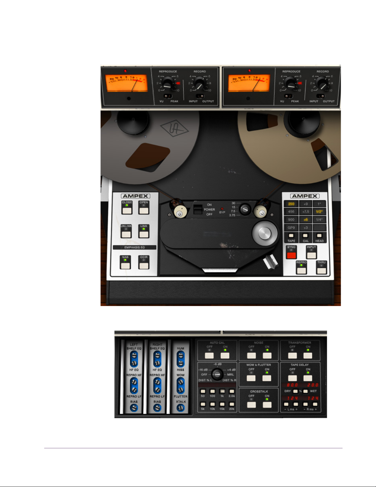
Ampex ATR-102 Screenshots
Figure 1. The UAD Ampex ATR-102 plug-in window
Figure 2. Ampex ATR-102 secondary controls in “open” mode
UAD Powered Plug-Ins Manual - 19 - Chapter 2: Ampex ATR-102
Page 20

Operational Overview
Famous Tape Sound
Mixdown Tape Deck
Multiple Tape Types
The UAD Ampex ATR-102 provides all of the original unit’s desirable analog
sweetness. Like magnetic tape, users can dial in a clean sound, or just the
right amount of harmonic saturation.
The primary purpose of the UAD Ampex ATR-102 is to obtain tape mixdown
sonics within the DAW environment. To obtain the classic tape mixdown
sound, instantiate the plug-in as the last insert on the output bus, after other
processing is applied (or possibly as the second-to-last insert, before a
brick-wall processor such as the (UAD Precision Limiter). Of course, creative
“non-standard” results can be obtained by placing the Ampex ATR-102 in
any channel insert or on busses in a send/return configuration.
The UAD Ampex ATR-102 models seven popular magnetic tape formulas.
Each type has its own subtle sonic variation, distortion onset, and tape compression characteristics. The tape types that can be selected depend on the
active tape speed and head type; all tape types are not available for all tape
speeds and head types. Lower fidelity types are included to facilitate more
signal coloration options.
Multiple Tape Heads
Multiple Tape Speeds
Multiple Calibration Levels
The original hardware machine was manufactured with an interchangeable
head block system which enabled the system to be quickly converted to use either 1/4” or 1/2” tape stock by simply swapping out the heads and recalibrating the electronics. As track width increases, subtle improvements to stability, fidelity, and noise become apparent. A popular custom aftermarket
tape head is available which enables the use of 1” tape stock, enabling even
higher fidelity with its greater track widths. All three tape head widths are accurately modeled and selectable in the UAD Ampex ATR-102.
All four tape speeds in the original hardware are modeled in the UAD Ampex
ATR-102. Speeds of 3.75, 7.5, 15, and 30 inches per second (IPS) are available. Each speed provides distinct frequency shift, head bump, and distortion
characteristics. Higher speeds have higher fidelity; 3.75 IPS has a distinctively “lo fi” character.
Tape machines can be setup with different calibration levels, which entails setting unity gain from input through output based on the magnetic flux (amount
of magnetic field) of a given tape formulation. Different calibration levels provide different tape response characteristics for a given level into the recorder.
Four selectable calibration levels are available in the UAD Ampex ATR-102.
UAD Powered Plug-Ins Manual - 20 - Chapter 2: Ampex ATR-102
Page 21

Ancillary Noises Tape recorders have inherent signal noises that are a by-product of the elec-
tro-mechanical nature of the machine. While “undesirable” tape system noise
is historically considered a negative and was an attribute that pushed the
technical envelope for better machine design and tape formulas (and ultimately, “noiseless” digital recorders), noise is still an ever-present characteristic of the sound of using tape and tape machines.
The UAD Ampex ATR-102 models the hum, hiss, wow, flutter, and crosstalk
characteristics of the original hardware. These noise components can be individually disabled, adjusted, and/or exaggerated for creative purposes
(even though the servo-controlled, direct-drive capstan tape transport of the
original hardware provides excellent wow and flutter specifications).
Modeled Transformer
The original hardware was manufactured with isolation transformers, which
can color the signal. A common modification to the hardware tape machine
eliminates the transformers from the signal path to produce a (subjectively)
“cleaner” sound. UAD Ampex ATR-102 simulates the behavior of the transformers in the hardware circuit, and can be optionally disabled in the plug-in,
providing both sonic options.
Tape Delay A popular application of multi-head tape recorders is to employ them for slap-
back tape echo effects. If the machine is running in record mode but the recorded signal is monitored from the repro head (as opposed to the sync
head), the physical space between these two heads results in a short delay between the signal sent to the recorder and the monitored signal. When these
signals are combined with mixer routings, the classic slapback echo is manifest. The UAD Ampex ATR-102 implements the ability to reproduce this classic
effect with a simple set of controls, and expands the capabilities by extending
the available delay times beyond what is possible in the physical realm.
Automatic Calibration
The ability of a magnetic tape recorder, which has inherently non-linear response characteristics, to accurately reproduce an audio signal with a minimum of noise and distortion requires precise adjustments to the system electronics. The calibration settings are based on the current tape speed,
formulation, emphasis EQ, and tape width. The hardware must be meticulously re-adjusted each time a different tape, speed, emphasis EQ, or head
width is used (and for system wear and drift, even if these variables are not
changed). UAD Ampex ATR-102 has an automatic calibration feature that
tunes all calibration electronics with a single button.
UAD Powered Plug-Ins Manual - 21 - Chapter 2: Ampex ATR-102
Page 22

Low Level Tuning Even though automatic calibration is available, the individual controls that ad-
just calibration are exposed for sonic manipulation. Playback EQ, record
(tape) EQ, and record bias can easily be altered for manual calibration
and/or creative purposes.
Manual Calibration Tools
UAD Ampex ATR-102 includes the full suite of tools required to manually calibrate the recorder. Manual calibration tools are provided so expert users can
calibrate the system to their preferred methods for obtaining desired results.
The manual calibration tools consist of a tone generator (with multiple test
tones and levels), a distortion meter with digital readouts, and a full suite of
Magnetic Reference Laboratory (MRL) alignment tapes, which are used to calibrate playback electronics.
Mono/Stereo Operation
While the UAD Ampex ATR-102 is a true stereo processor designed primarily
for use in stereo-in/stereo-out configurations, it will also operate in
mono-in/stereo-out and mono-in/mono-out modes.
When used in a mono-in/stereo-out configuration, the mono input signal is
sent to both channels of the processor, which can then be adjusted independently. When used in a mono-in/mono-out configuration, adjusting any left or
right control will change both the left and right controls (the left/right controls
are always linked in mono mode).
Quick Setup Set up the plug-in by first adjusting Tape Speed, Tape Type (tape formulation),
and Emphasis EQ, or simply select a factory preset. Note that as you lower
the tape speed, the tape “sound” becomes more audible. Once this basic
setup is made, adjust the L/R Record (gain) levels, for more or less tape/circuit coloration/saturation.
Artist Presets UAD Ampex ATR-102 includes artist presets from prominent ATR-102 users.
Some of the artist presets are in the internal factory bank and are accessed
via the host application’s preset menu. Additional artist presets are copied to
disk by the UAD installer. The additional presets can be loaded using the Settings menu in the UAD Toolbar.
Primary & Secondary Controls
The graphical interface panel has two modes; open and closed. In closed
mode, the primary controls (those that are typically most used) are available
on the main panel interface and the tape reels are visible. Additional (typically less used) controls are available on the secondary panel in open mode.
The secondary controls panel (Figure 4 on page 31) is accessed by clicking
the OPEN button beneath the AMPEX label.
UAD Powered Plug-Ins Manual - 22 - Chapter 2: Ampex ATR-102
Page 23
Primary Controls
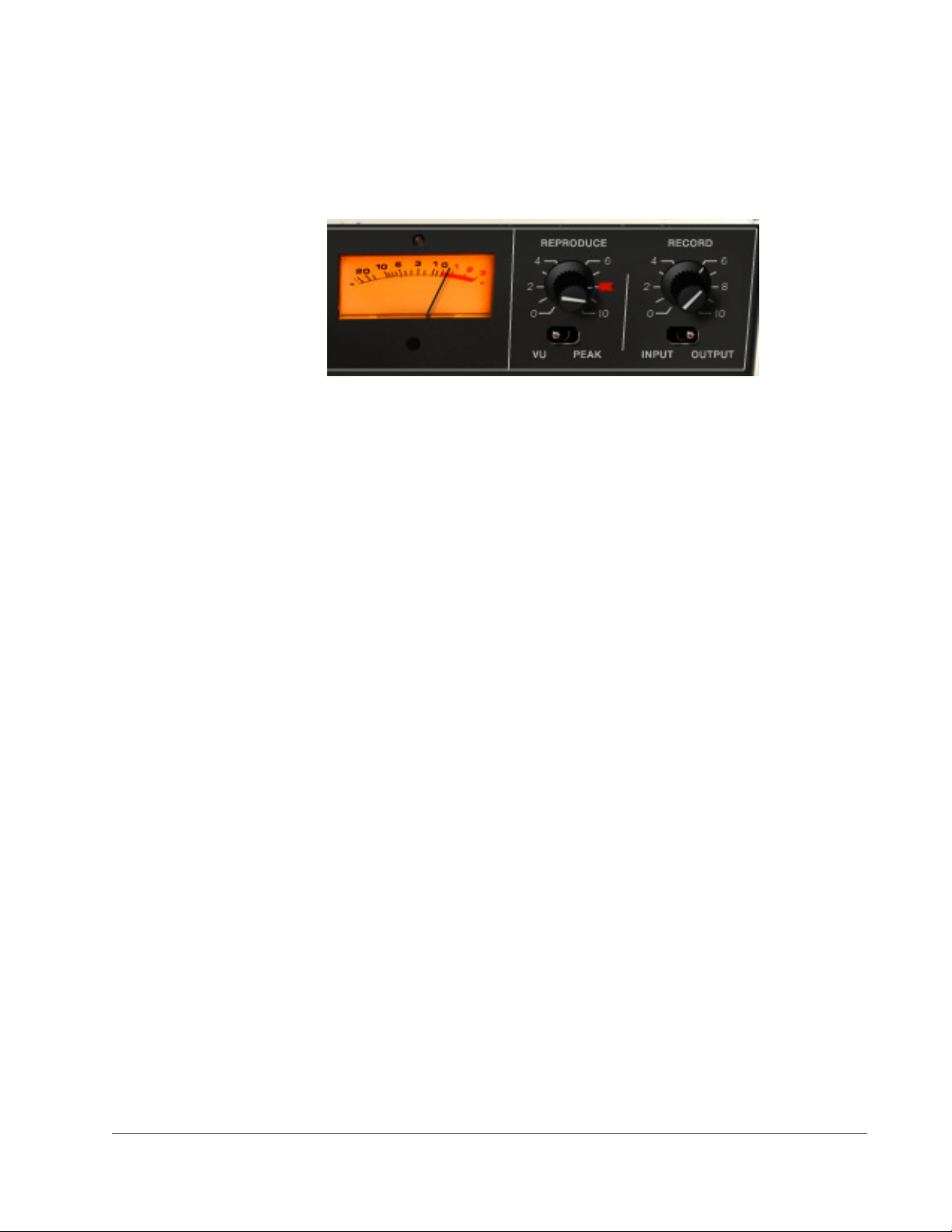
Meters The two Meters display signal levels of the plug-in for the left and right chan-
nels. Meter ballistics of the original hardware are modeled. The Meters can
be switched to display input or output levels in peak or VU modes.
Figure 3. One side of the Ampex ATR-102 “penthouse” showing meter and I/O controls
The plug-in operates at an internal level of –12 dBFS. Therefore a digital signal with a level of –12 dB below full scale digital (0 dBFS) at the plug-in input
will equate to 0 dB on the Meters when Reproduce is in its calibrated position,
which is marked with the “red arrow sticker.”
When Path Select is set to Thru, the Meters indicate signal levels at the input
of the plug-in prior to processing.
Note: Although there are separate left/right Meter controls for VU/Peak and
Input/Output, these controls are permanently linked and cannot be switched
individually for the left and right channels.
Input/Output These switches change the Meter to display levels at the input or output of the
plug-in. Input metering is a UAD-only feature which is unavailable in the original hardware.
Input
When in Input mode, the Meter reflects the signal level after the Record (input)
gain when Path Select is set to Sync or Repro. In Input mode when Path Select
is set to Thru, the Meter reflects the pre-processed (raw input) signal level.
Output
When in Output mode, the meter reflects the signal level at the output of the
plug-in, which is just after the Reproduce (output) gain.
Peak/VU This switch is used to change Meter behavior between Peak or VU modes.
UAD Powered Plug-Ins Manual - 23 - Chapter 2: Ampex ATR-102
Page 24
Clip LED The left and right channels each have a Clip LED, just above the Meter.
The Clip LED is not in the original hardware; it is a UAD-only feature.
The Clip LED illuminates only when the machine’s audio electronics clip. The
Clip LED is not affected by the recorded tape signal, even if the tape is overloaded and distorting.
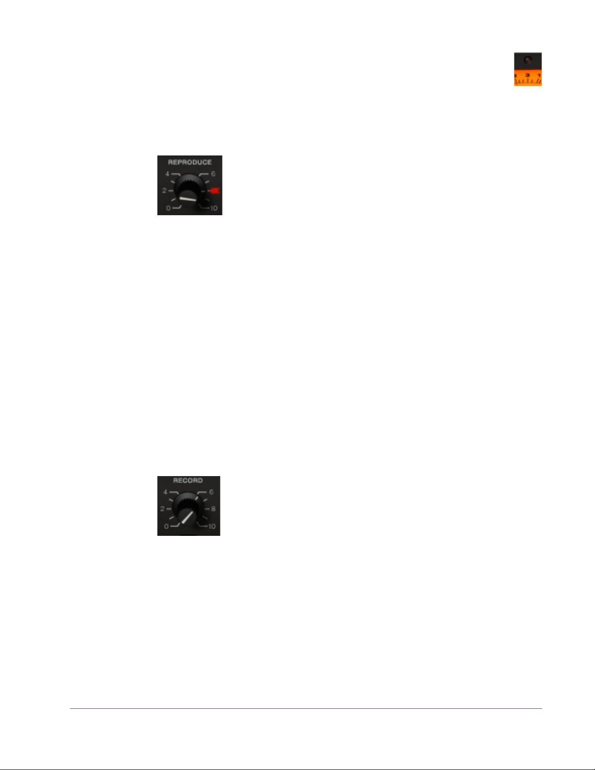
Reproduce Reproduce adjusts the signal level coming off the virtual tape
before the signal is sent to the Meters. There are two Reproduce
controls, one each for the left and right channels. The left/right
Reproduce controls can be adjusted individually, or simultaneously adjusted when Link mode (page 25) is active.
The available range is –∞ dB (off) to +9.48 dB. The default value of 0 dB is
the “calibrated position” which is marked with a “red arrow sticker.” Reproduce is not affected by Auto Cal.
Tip: Click the “REPRODUCE” label text to return Reproduce to 0 dB.
The Meters accurately reflect the output level (when set to Output mode) even
if Reproduce is not in its calibrated position. However, if Reproduce is moved
from the “cal” position, the Meters will no longer correspond to a particular
level being recorded onto the virtual tape. In this case, the Meters will not reflect the actual “operating level” of the tape because Reproduce changes the
signal level coming off the tape before it is sent to the Meters.
Note: The graphical interface panel values for Reproduce, which range from
0 – 10, are arbitrary and do not reflect a particular dB value.
Record Record adjusts the signal level into the plug-in and the tape cir-
cuitry. There are two Record controls, one for the left channel
and one for the right. These left/right Record controls can be
adjusted individually, or simultaneously when Link mode
(page 25) is active.
The available range is –∞ dB (off) to +9.3 dB. The default value is 0 dB. The
graphical interface panel values, which range from 0 – 10, are arbitrary and
do not reflect a particular dB value.
Tip: Click the “RECORD” label text to return the Record value to 0 dB.
UAD Powered Plug-Ins Manual - 24 - Chapter 2: Ampex ATR-102
Page 25
Record is a primary “color” control for the plug-in. Just like genuine magnetic
tape, lower Record levels will have a cleaner sound, while higher levels result
in more harmonic saturation and coloration. Higher Record levels will also increase the output level from the plug-in. The Reproduce control can be lowered to compensate if unity gain operation is desired.
Reproduce/Record Controls Arrangement
Note that the Reproduce control is to the left of the Record control, which is
atypical of most signal flow designs, where inputs usually precede outputs
(flowing from left to right). This quirky arrangement of the Ampex ATR-102
I/O controls, where the input control “follows” the output control, is true to the
original hardware design. In Controls View, the Record (input) control precedes the Reproduce (output) control.
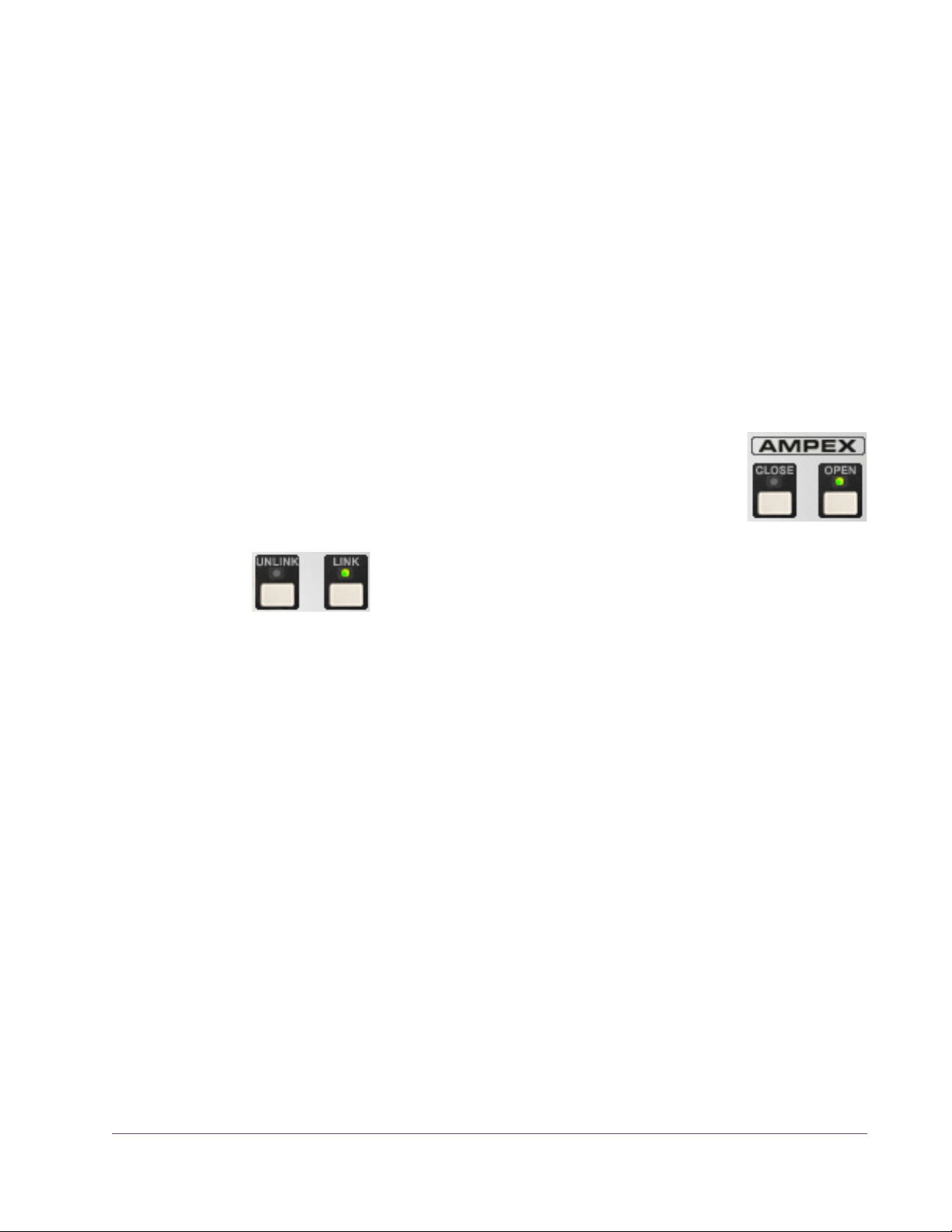
Open/Close The secondary controls (Figure 4 on page 31) are accessed
by clicking the OPEN button beneath the AMPEX label. Conversely, the panel is closed by clicking the CLOSE button.
Link/Unlink Link mode is a software-only addition that enables controls
that are identical for the left and right channels to be linked
for ease of operation when both channels require the same
values, or unlinked when independent left/right control is desired. In other
words, left/right channel controls are ganged together in link mode.
The Link parameter is stored within presets and can be accessed via automation.
Note: Although there are separate left/right Meter controls for VU/Peak and
Input/Output, these controls are permanently linked and cannot be switched
individually for the left and right channels, even if Unlink mode is active.
Link
In Link mode, modifying any left or right channel control causes its adjacent
stereo counterpart control to snap to the same position.
Important: When Unlink mode is active and Link is enabled, the left chan-
nel control values are copied to the right channel. Control offsets between
channels are lost in this case.
UAD Powered Plug-Ins Manual - 25 - Chapter 2: Ampex ATR-102
Page 26
When Link is active, automation data is written and read for the left channel
only. In this case, the automation data for the left will control both channels.
Additionally, changing the right channel parameters from a control surface or
when in “controls only” (non-GUI) mode will have no effect.
Unlink
When Unlink is active, the controls for the left and right channels are independent. When unlinked, automation data is written and read by each channel
separately.
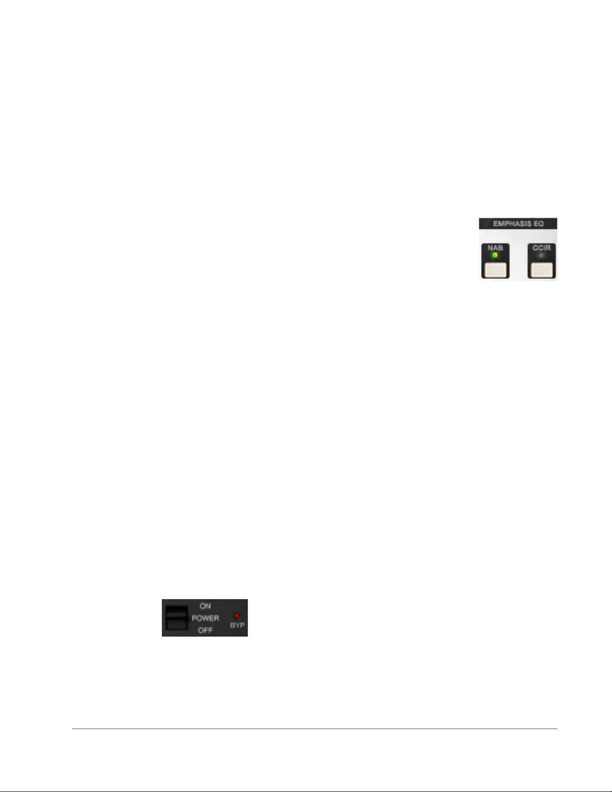
Emphasis EQ The Emphasis EQ buttons determine the active Emphasis EQ
values and the frequency of the Hum noise. NAB or CCIR
curves can be selected when the Tape Speed is 7.5 or 15
IPS. When the Tape Speed is 30 IPS, neither value is available (the LEDs are dimmed) because the EQ is fixed with the
AES emphasis curve, per the original hardware. At 3.75 IPS, only NAB is
available (as it is with the hardware).
When the value is set to NAB (traditionally the United States standard), the
Hum Noise frequency is 60 Hz. When set to CCIR (traditionally the standard
in Europe and other regions), the Hum Noise frequency is 50 Hz. See “Noise
Enable” on page 33 and “Hum” on page 33 for more information about
Hum.
Tape Speed and Emphasis EQ were originally practical controls for recording
duration versus noise and local standards. Historically, the origin of the tape
machine (US or European) dictated the built-in EQ emphasis, but later machines like the Ampex ATR-102 had both circuits available.
CCIR (also known as IEC1) is the EQ pre-emphasis made famous on British
records and is considered the technically superior EQ; many say this EQ was
part of the “British sound” during tape’s heyday. NAB (also known as IEC2)
was the American standard with its own sound. AES is truly standardized at
30 IPS and is the sole EQ found on the Ampex ATR-102 at 30 IPS.
Power Power is the plug-in bypass control. When set to OFF, em-
ulation processing is disabled, the Meters and control LEDs
are dimmed, the Bypass LED illuminates, and DSP usage is
reduced. Power is useful for comparing the processed settings to the original
signal.
UAD Powered Plug-Ins Manual - 26 - Chapter 2: Ampex ATR-102
Page 27
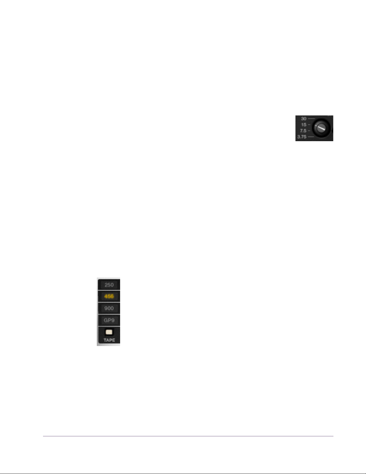
OFF is similar to the Thru position in the Path Select control (page 29) except
that the Meters are still active when the Thru control is used. However, in this
state, the Meters indicate signal levels at the input of the plug-in prior to processing.
Note: DSP usage is reduced only when DSP LoadLock is disabled. If DSP
LoadLock is enabled (the default setting), activating OFF will not reduce DSP
usage.
Tape Speed The Tape Speed control determines the speed of the tape trans-
port, in inches per second (IPS). Tape Speed affects the recorder’s fidelity and associated “head bump” sonics. Head
bump is bass frequency build-up that occurs with magnetic tape;
the dominant frequencies shift according to transport speed.
To change the Tape Speed value, click the IPS text values, or drag the knob,
or click the knob then use the mouse scroll wheel.
15 IPS is considered the favorite for rock and acoustic music due to its low frequency “head bump” (low frequency rise) and warmer sound, while 30 IPS is
the norm for classical and jazz due to its lower noise floor, greater fidelity and
flatter response. 7.5 and 3.75 IPS are also available for an even more colored experience, with even greater frequency shift and other artifacts.
Note: The available parameter ranges of Tape Type, Head Width, and Em-
phasis EQ are affected by Tape Speed. See Table 6 on page 43 for details.
Tape Type Tape Type selects the active tape stock formulation. Seven
Tape Types are modeled in the UAD Ampex ATR-102. To select the Tape Type, click the TAPE button to cycle through the
available types, or click directly on the Tape Type value label.
The active Tape Type is highlighted in yellow.
Note: The available Tape Types and defaults are dependent
on the current Tape Speed and Head values. The available
Tape Types, and the associated Tape Speed and Head values,
are shown in Table 6 on page 43.
Each type has its own subtle sonic variation, distortion onset, and tape compression characteristics. Generally speaking, the lower the Cal Level for each
formula, the higher the signal level required to reach saturation and distortion.
UAD Powered Plug-Ins Manual - 27 - Chapter 2: Ampex ATR-102
Page 28
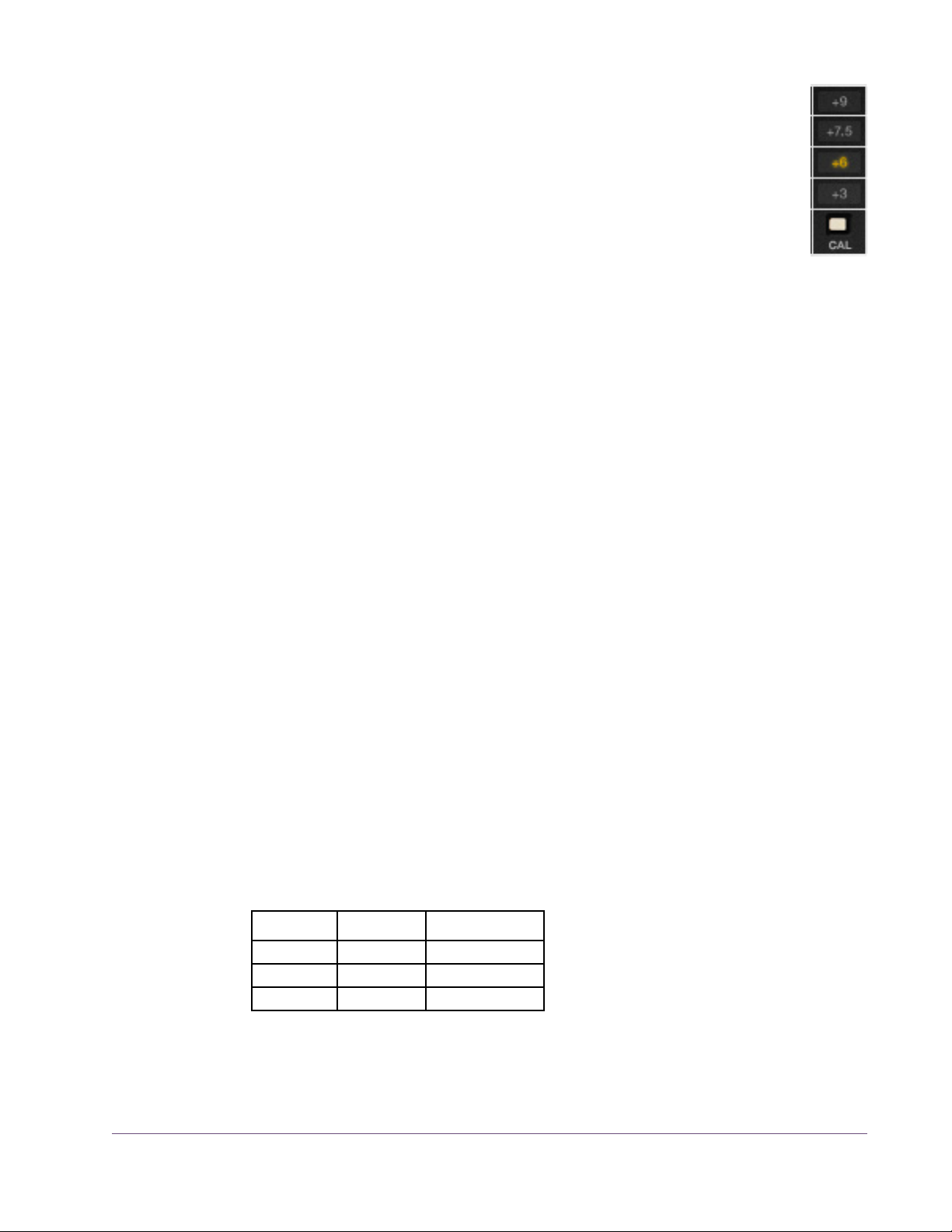
Cal Level Cal Level automatically sets tape calibration/fluxivity. The Cal Level
setting takes care of the setup one would need to make under equivalent hardware operation, and sets the reference tape/flux level without disturbing the (unity) gain of the plug-in.
To select the Cal Level, click the CAL button to cycle through the available levels, or click directly on the calibration value label. The active
Cal Level is highlighted in yellow. The default value is +6 dB.
Because Cal Level affects the operating levels in the plug-in, it can be used to
compensate for overly high (or low) levels at the input of the plug-in. For example, if the input is too hot, lowering the Cal Level will reduce the signal level
without changing Record, which can affect the tape saturation characteristics.
Note: The noise floor is affected by the Cal Level when Noise Enable
(page 33) is active.
As tape formulas advanced, their output level increased, thus lowering relative noise floor. Under normal use, the machine would be calibrated to the
tape’s output level. However, sometimes the machine is under-calibrated to
leave more headroom for a broader sweet spot or to prevent electronics from
clipping. Therefore, one can “go traditional” and calibrate to the recommended levels (Table 1), or select a non-corresponding calibration setting.
As an example, if 456 is the selected Tape Type and when Cal is set at +6
(6 dB higher than the NAB tape standard), the reference flux level is 355
nWb/m (nanoweber per meter) and is 10 dB below the point where THD
reaches 3% (referred to as the maximum operating level). Therefore, with a
1 kHz test tone at –12 dBFS sent to the plug-in, with Tape Type set to 456, Cal
set to +6, and Auto Cal enabled, output levels of the plug-in will match the input level and fluxivity on the tape will be 355 nWb/m.
The tape manufacturer’s recommended calibration settings for each Tape
Type are shown in Table 1.
Table 1. Tape Manufacturer’s Recommended Calibration Levels
Tape Type Calibration Flux Level
111 +0 dB 177 nWb/m
35-90 +3 dB 251 nWb/m
250 +3 dB 251 nWb/m
UAD Powered Plug-Ins Manual - 28 - Chapter 2: Ampex ATR-102
Page 29
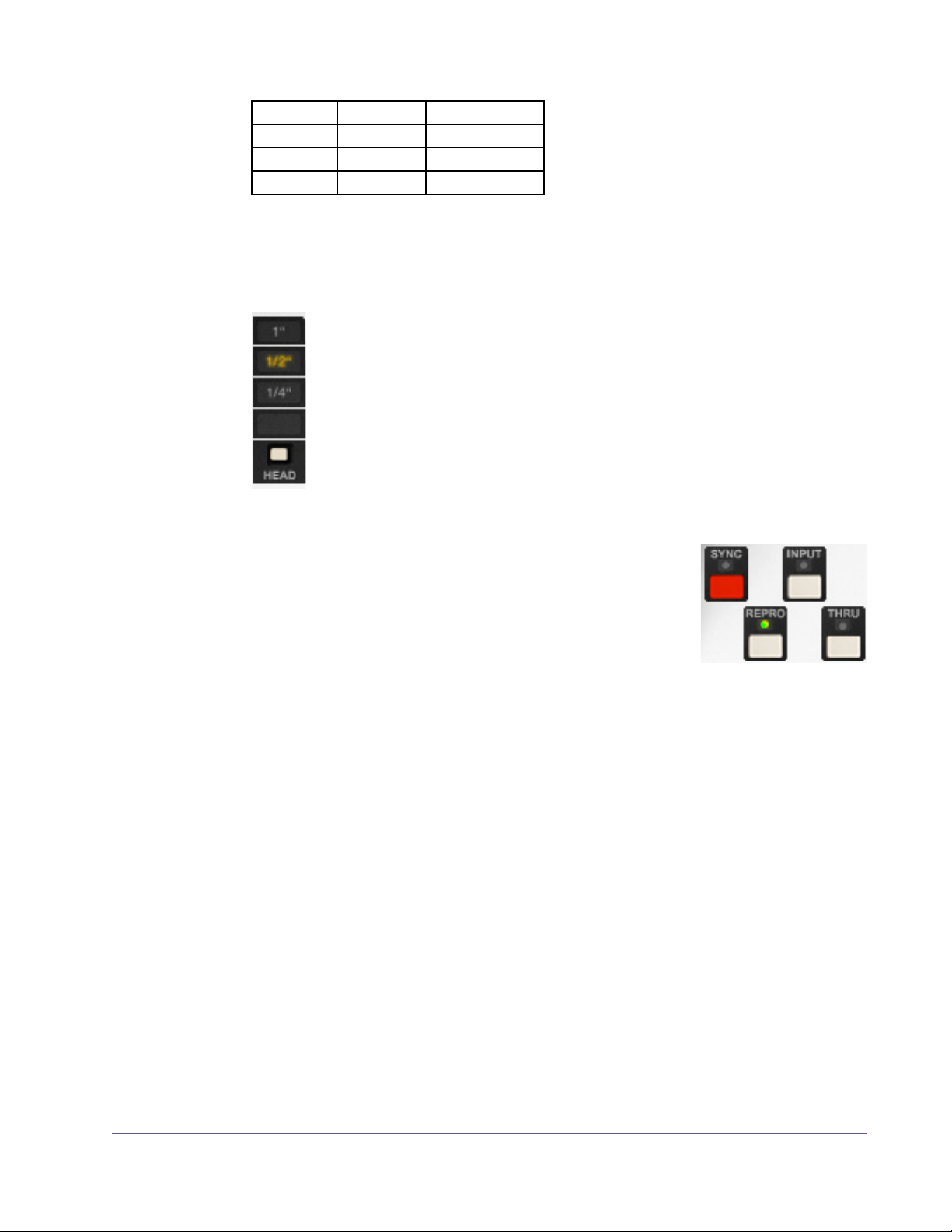
Table 1. Tape Manufacturer’s Recommended Calibration Levels
456 +6 dB 355 nWb/m
468 +6 dB 355 nWb/m
900 +9 dB 502 nWb/m
GP9 +9 dB 502 nWb/m
Tip: The UAD Ampex ATR-102 default presets bank offers a variety of preset
Tape Type, Tape Speed, CAL level, and EQ configurations that are commonly
used for the recording of specific genres.
Head Width This control specifies the active tape head model. Head Widths of
1/4,” 1/2,” or 1” can be selected.
To select the Head Width, click the HEAD button to cycle through the
available values, or click directly on the value label. The active Head
Width is highlighted in yellow.
Note: At tape speeds of 3.75” and 7.5” only the 1/4” head can be
used. At these speeds, the 1/2” and 1” heads cannot be selected.
Path Select The Path Select buttons specify which of the four possi-
ble signal paths is active in the Ampex ATR-102. The
active mode is indicated by an illuminated LED above
its associated button. The default value is Repro.
Sync
Sync mode models the sound of direct tape recording and playback via the
sync/record head, plus all corresponding machine electronics.
Sync mode is generally not used for playback due to its poorer frequency response, but it is included for authenticity and creative purposes.
Repro
Repro mode models the sound of tape recording through the record head and
playback through the reproduction head, plus all corresponding machine
electronics.
Input
Input mode emulates the sound of the Ampex ATR-102 through the machine
electronics only, without tape sonics. This is the scenario when the machine is
in live monitoring mode but the tape transport is not running.
UAD Powered Plug-Ins Manual - 29 - Chapter 2: Ampex ATR-102
Page 30
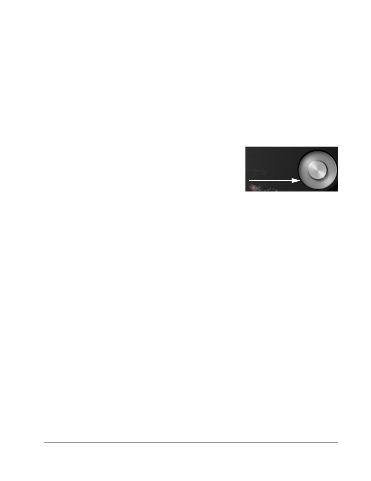
Thru
Click capstan
to start/stop
reels animation
Thru is a processor bypass control. When Thru is enabled, all controls are inactive, emulation processing is disabled, and DSP usage is reduced.
Thru behavior is similar to that of the OFF position in the POWER control
(page 26), except that the Meters are still active in Thru mode. In this state, the
Meters indicate signal levels at the input of the plug-in prior to processing.
Note: DSP usage is reduced only when DSP LoadLock is disabled. If DSP
LoadLock is enabled (the default setting), activating Thru will not reduce DSP
usage.
Tape Reels Animation
When the secondary controls panel is closed
(Figure 1 on page 19), by default the graphical tape reels “spin” if the DAW transport is
running. The tape reels animation can be disabled by clicking the capstan graphic.
Re-clicking the capstan will re-start the animation.
The “spin state” is saved until it is changed again.
Note: Spinning reels automation is not supported in all hosts. In Sonar, the
plug-in must be configured as a “tempo-based effect” for reels animation.
UAD Powered Plug-Ins Manual - 30 - Chapter 2: Ampex ATR-102
Page 31

Secondary Controls
The secondary controls (Figure 4 below) adjust the various
calibration, ancillary noise, tone generator, and tape delay
parameters. The secondary controls panel is accessed by
clicking the OPEN button beneath the AMPEX label.
Figure 4. UAD Ampex ATR-102 secondary controls
Auto Cal The Ampex ATR-102 has individual calibration controls for ad-
justing sync (record) EQ, reproduction (playback) EQ, and
record bias, which are used to compensate for the inherent
non-linearities of tape systems. On the hardware, these controls
are typically adjusted to calibrate the system for optimum response compensation due to tape non-linearities whenever the tape type, tape speed, emphasis EQ, or head width are changed.
When the Auto Cal (Automatic Calibration) ON button is clicked, the calibration EQ and bias controls are automatically adjusted to their “flat” calibrated
position for the currently active Tape Type, Tape Speed, Emphasis EQ, and
Head Type. The Auto Cal ON LED illuminates green when the calibration parameters (Shelf EQ, HF EQ, Repro HF, Repro LF, and Bias) are in their calibrated position.
Auto Cal is enabled by default. When Auto Cal is ON, the calibration parameters (Shelf EQ, HF EQ, Repro HF, Repro LF, and Bias) change values
whenever Tape Type, Tape Speed, Emphasis EQ, or Head Type is modified.
When Auto Cal is OFF, the calibration parameters do not change values
when Tape Type, Tape Speed, Emphasis EQ, or Head Type is modified.
Important: Any calibration settings made manually are lost when Auto Cal
is activated. Consider saving manual settings as a preset before activating
Auto Cal.
UAD Powered Plug-Ins Manual - 31 - Chapter 2: Ampex ATR-102
Page 32

After Auto Calibration occurs, the automatically adjusted pa-
rameters can be modified to any other value if desired. If a cal-
ibration parameter is adjusted while Auto Cal is ON, the ON
LED illuminates in red instead of green, indicating that the system is no longer in the calibrated state. If the moved controls are subsequently
returned to their original position, the LED will return to its green state, indicating the unit is back in calibration.
Tip: To return any of the individual calibration controls to their “flat” (cali-
brated) position, click the label text adjacent to the control (or, simply re-click
Auto Cal to return all calibration controls to their “flat” position).
The “Manual Calibration Procedure” on page 39 has instructions for perform-
ing system calibration manually.
Record EQ The Record EQ controls (HF EQ and Shelf EQ) are applied in
the tape recording circuit and affect tape saturation characteristics. They compensate for common residual HF loss due to
bias optimization and system filtering, and affect HF content in
the signal prior to the tape non-linearity.
HF EQ
HF EQ provides high frequency emphasis in the signal recorded to tape.
Shelf EQ
Shelf EQ is another control (in addition to HF EQ) provided to compensate for
tape non-linearity. Although adjustment of this control is not part of the Ampex
factory calibration procedure, it can be used for customized manual calibrations or creative purposes.
Repro EQ The Repro EQ controls (Repro HF and Repro LF) are post-head
controls for tape playback calibration. They affect the signal
coming out of the tape circuitry in both Repro and Sync
modes.
The Repro EQs are used as filters to shape the frequency response of the system in maintaining a flat response and enable compensation for any tape frequency loss or head wear.
UAD Powered Plug-Ins Manual - 32 - Chapter 2: Ampex ATR-102
Page 33

Repro HF
Adjusts the tape playback high frequency content when Path Select is set to
Sync or Repro.
Repro LF
Adjusts the tape playback low frequency content when Path Select is set to
Sync or Repro.
Bias This control adjusts the amount of bias in the record signal.
Bias is defined as an oscillator beyond the audible range applied to the audio at the record head, allowing for adjustment
of the record behavior. Ideal bias voltage settings provide maximum record
sensitivity and low distortion. Intentionally overbiasing is a common technique
especially for “tape compression” which produces a warmer, gently saturated sound. Underbiasing can also be used to add distortion and other nonlinear responses, similar to gate chatter or cold solder joints; extremely low
voltages may even cause audio to drop out entirely.
Bias voltage, HF/Shelf EQ, and Emphasis EQ (CCIR, NAB, AES) all work together to provide a linear response to the recorded signal. The “flat” (calibrated position) is determined by tape speed, tape type, emphasis EQ, and
head width.
Noise Enable This is a global enable control for the Hum and Hiss effect.
When Noise is ON, the level of Hum and Hiss can be independently adjusted using the Hum and Hiss Level controls.
The default values of 0 dB for Hum and Hiss are the actual modeled level in
the original hardware. Noise is not affected by automatic calibration.
Hum Determines the amount of Hum in the signal. Hum is added after the
tape circuitry. This control affects both the left and right channels.
Noise Enable must be ON for the Hum control to function.
The default value of 0 dB for Hum is the actual modeled level in the original
hardware. This default value can be offset by ±25 dB.
The Hum frequency is dependent on the Emphasis EQ control (page 26). The
frequency is 60 Hz when set to NAB (US) and 50 Hz when set to CCIR (European).
UAD Powered Plug-Ins Manual - 33 - Chapter 2: Ampex ATR-102
Page 34

When Tape Speed is set to 30 IPS, the green Emphasis EQ LEDs are not illuminated (and cannot be switched), indicating that the Emphasis EQ is set to
AES. However, the Hum frequency can still be set for 30 IPS mode by setting
Emphasis EQ to NAB (for 60 Hz) or CCIR (for 50 Hz) prior to setting Tape
Speed to 30 IPS.
Note: When Tape Speed is 3.75 IPS, only 60 Hz is available.
Hiss Hiss determines the amount of tape hiss in the tape playback signal.
The default value is 0 dB and can be offset by –25 dB to +50 dB for creative purposes. Noise Enable must be ON for this control to function.
Like the hardware, the amount of hiss is dependent on settings of the various
controls and may subtly change based on the values of Path Select, Tape
Type, Emphasis EQ, Cal Level, Bias, Playback EQs, and Output Level.
Hiss Level is not affected by automatic calibration, so its level does not change
with Tape Speed. When Hiss Level is at its default position (0 dB), the amount
of hiss present in the signal is as if the Tape Speed is 15 IPS. To emulate the
amount of hiss at the other tape speeds, enter the offsets from Table 2.
Wow & Flutter Enable
Table 2. Hiss Level Offsets
Tape Speed Hiss Level Setting
30 IPS –8 dB
15 IPS 0 dB
7.5 IPS 12.5 dB
3.75 IPS 17 dB
Note: Because hiss noise is an element of tape playback, Hiss is disabled
when Path Select is set to Input.
These buttons are global enable/disable controls for the Wow
and Flutter effects. When Wow & Flutter is ON, the level of
Wow and Flutter can be independently adjusted using the
Wow and Flutter Level controls.
Wow and Flutter are “undesirable” pitch modulations induced by the mechanical components of the tape transport. Wow is a by-product of capstan
irregularities, while flutter is a by-product of tape stretching and sticking. Both
can be effectively used for creative purposes.
UAD Powered Plug-Ins Manual - 34 - Chapter 2: Ampex ATR-102
Page 35
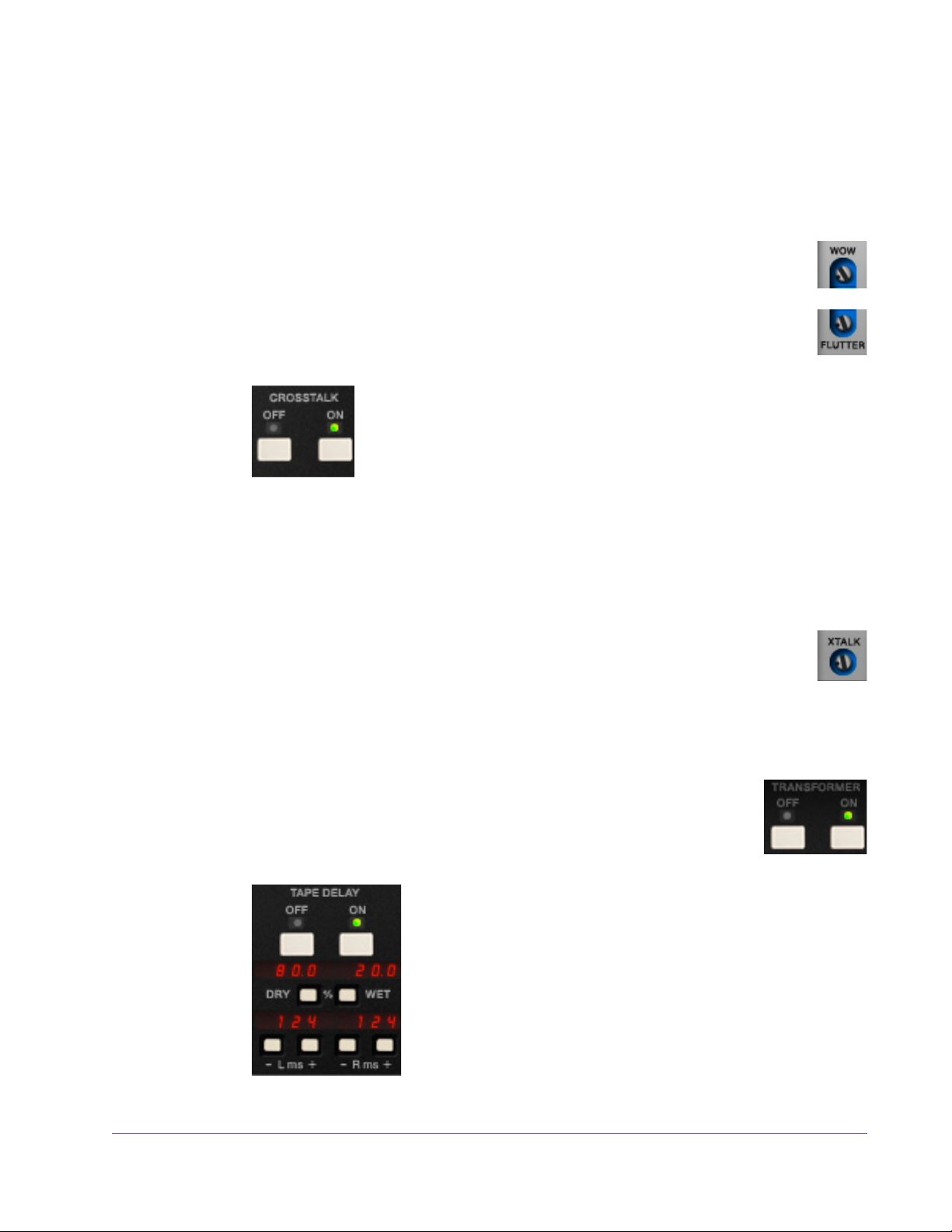
Wow usually refers to very low frequency fluctuations, while Flutter refers to
faster fluctuations. Wow and flutter is measured as the percentage of deflection from the original pitch. Both are more pronounced at lower tape speeds.
Note: Wow and Flutter levels change with Tape Speed, but they are not af-
fected by automatic calibration.
Wow Determines the amount of Wow in the signal. Wow & Flutter Enable
must be ON for this control to function.
Flutter Determines the amount of Flutter in the signal. Wow & Flutter Enable
must be ON for this control to function.
Crosstalk Enable These buttons are global enable/disable controls for the
Crosstalk Level (XTALK) parameter. When Crosstalk is ON, the
amount of Crosstalk can be adjusted using the Crosstalk Level
control.
Crosstalk is the amount of signal bleed between the left and right channels.
Crosstalk sonics can vary based upon the Tape Speed and Head Width pa-
rameters, however the amount of crosstalk does not vary with these settings.
Crosstalk Level
This control determines the amount of signal crosstalk. Crosstalk Enable must be ON for the Crosstalk Level control to function. The default
value of –45 dB is the actual modeled level in the original hardware.
The available range is –50 dB to –10 dB. Crosstalk Level is not affected by automatic calibration.
Transformer Enable
These ON/OFF buttons enable and disable the transformer circuit of the Ampex ATR-102. For an overview of this feature, see
“Modeled Transformer” on page 21.
Tape Delay These parameters control the built-in Tape Delay, which
creates tape echo effects. For an overview of this feature,
see “Tape Delay” on page 21. The Tape Delay controls
are not available in the original hardware.
Note: Tape Delay is not available when Path Select is set
to Input or Thru, nor when the Manual Calibration Tools
are active.
UAD Powered Plug-Ins Manual - 35 - Chapter 2: Ampex ATR-102
Page 36

Tape Delay Enable
Delay Time Defaults
• 30 IPS: 62 ms
• 15 IPS: 124 ms
• 7.5 IPS: 248 ms
• 3.75 IPS: 496 ms
These buttons are global enable/disable controls for the Tape Delay effect.
When Tape Delay is ON, its red numerical display is active, and other Tape
Delay parameters can be adjusted.
Dry/Wet Mix
The Dry/Wet pushbuttons control the mix of the Tape Delay effect. The
amount of dry and wet signals are displayed as percentages.
Click the Dry button to increase the dry signal level by 1%, or the Wet button
to increase the delayed signal level by 1%.
Tip: Hold the Dry/Wet buttons down to rapidly change the mix values. For
fine control in increments/decrements of 0.1%, hold down Shift while changing values.
Delay Time
The left and right channel delay times can be independently adjusted with
these controls. Click the “+” or “–” buttons to change the delay times in increments of 10 milliseconds. The available range is 0 – 1000 milliseconds.
Tip: Hold the +/– buttons down to rapidly change the delay times. For fine
control in increments/decrements of 1ms, hold down Shift while changing
values.
The default Delay Time values depend on the current
Tape Speed, and represent the actual delay time
that would occur in the physical realm, reflecting the
elapsed time between the signal put on tape at the
record/sync head and its reproduction at the playback/repro head. These “physical” default times
are shown at right.
Important: When the tape speed is changed, the current delay time is
changed to reflect the new “physical time” between the sync and repro heads
for the new tape speed, and previously set values are lost (see tip below).
Tip: To retain custom delay times when changing Tape Speed, hold Shift
when changing Tape Speed.
UAD Powered Plug-Ins Manual - 36 - Chapter 2: Ampex ATR-102
Page 37

Manual Calibration Tools
These controls are the suite of tools included to perform
manual calibration of the recorder. These UAD-only
tools are not in the original hardware. Manual calibration is entirely optional, as the Auto Cal feature can
quickly and automatically calibrate the system.
The manual calibration tools consist of an “external”
tone generator with multiple test tones and levels, a distortion meter with digital readouts, and a full suite of
modeled Magnetic Reference Laboratory (MRL) alignment tapes.
Note: The Manual Calibration Tools are operational only when Path Select
is set to Sync or Repro. Additionally, the tools may not operate in some hosts
unless audio is present on the track containing the plug-in and the transport is
running. Placing the plug-in on an aux, bus, or master output may eliminate
this host limitation.
This section describes the functions of the manual calibration tools. For instructions on how to use the tools to perform a manual system calibration, see the
“Manual Calibration Procedure” on page 39.
About MRL Alignment Tapes
Alignment tapes are carefully recorded with accurate and consistent flux levels and test tone frequencies. They are constant companions to all well-maintained professional tape machines. Different alignment tapes are required for
each tape speed, head width, equalization standard (CCIR/IEC or NAB),
and fluxivity level.
Alignment tapes are required for system calibration and adjustment so that
playback of previously-recorded session tapes will have correct and consistent equalization and levels, regardless of when, or where, the session tape
was originally recorded.
After tape playback system EQ and levels are calibrated to match the
known-to-be-correct values of the alignment tape(s), the record-side alignment
is performed. The entire record/playback system will then have proper EQ
and gain structuring.
Magnetic Reference Laboratory (“MRL”) is a company that produces alignment tapes. The MRL tapes used in the UAD Ampex ATR-102 are fringing
compensated. In-depth discussions about fringing compensation and system
alignment are beyond the scope of this manual; thorough resources are available from the MRL website at: http://www.mrltapes.com
UAD Powered Plug-Ins Manual - 37 - Chapter 2: Ampex ATR-102
Page 38

Manual Cal Knob The Manual Cal knob performs two functions: it sets the
signal level of the “external” test tone generator for
record calibration, and specifies when alignment tapes
are to be used for playback calibration.
When set to –16 dB, –6 dB, or +4 dB, a generated sine wave test tone at the
frequency specified by the Tones buttons is sent to the input of the record circuitry. This mode emulates sending external test tones into the system. The
level of the test tone is set by the knob position and remains static regardless
of other parameter values.
When set to MRL, a test tone from the “alignment tape” is sent into the playback circuitry. The MRL frequency is also specified by the Tones buttons, but
the levels used are from the calibrated alignment tape. Therefore the MRL tone
levels are dependent on other tape parameter values.
Tones The Tones buttons set the frequency of the “external” test
tone generator and the MRL tape test tones. Tone frequencies of 50 Hz, 100 Hz, 1 kHz, 2.5 kHz, 5 kHz, 10
kHz, 15 kHz, and 20 kHz are available.
Click a button to specify that frequency; the active frequency’s button is shadowed gray as if in the “down” position.
Distortion Meter The red numerical display, between the Manual Cal
knob and the Tones buttons, represents the amount (dis-
played as a percentage) of third harmonic distortion
present in each of the left and right channels. This feature can be useful for
custom calibration techniques.
When the Manual Cal knob is set to –16 dB, –6 dB, or +4 dB, the value represents third harmonic distortion in the tape playback circuit. Generally
speaking, increasing Record (input) will increase distortion while in this
mode, as tape saturation increases. If Bias is set very low, distortion may increase at lower Cal Levels.
Note: When the Manual Cal knob is set to MRL, the Distortion Meter is inac-
tive (there is no distortion display in this mode).
UAD Powered Plug-Ins Manual - 38 - Chapter 2: Ampex ATR-102
Page 39

Manual Calibration Procedure
Manual calibration tools are provided so expert users can calibrate the system to their preferred methods for obtaining desired results. For example,
some technicians may prefer adjustments for lowest distortion at a certain frequency; setting bias for maximum sensitivity (instead of overbiasing); or other
non-standard techniques.
The calibration procedure described here is the most commonly used technique, and is the (albeit simplified) method recommended by the Ampex Operation and Service Manual.
Important: Manual calibration is not required to use UAD Ampex ATR-102.
Following this procedure will result in the same (or nearly the same) values obtained by simply using the Auto Cal feature.
Tip: When making manual calibration settings, consider disabling Auto Cal
so the manually calibrated values are not accidentally lost if any of the controls that force automatic calibration (Tape Type, Tape Speed, Emphasis EQ,
and Head Width) are inadvertently modified.
Preparation • Reduce monitoring system volume to avoid loud sine wave Tones.
• Insert UAD Ampex ATR-102 on the DAW output bus (see note below).
• Set Path Select to Repro mode (Sync mode is not supported for manual cal).
• Set left and right Meter Input/Output switches to the “OUTPUT” position.
• Set left and right Meter Peak/VU switches to the “VU” position.
• Set Tape Speed, Tape Type, Cal Level, and Head Width to desired values.
• If Tape Speed is set to 3.75 IPS, set Cal Level to +3 dB.
• Disable Noise Enable (excessive Hiss may contribute to incorrect results).
• Do not change the above settings throughout the procedure.
• For related information, see the Manual Calibration Notes at the end of this
chapter.
Note: The Manual Calibration Tools are operational only when Path Select
is set to Sync or Repro. Additionally, the tools may not operate in some hosts
unless audio is present on the track containing the plug-in and the transport is
running. Placing the plug-in on an aux, bus, or master output may eliminate
this host limitation.
UAD Powered Plug-Ins Manual - 39 - Chapter 2: Ampex ATR-102
Page 40

To manually calibrate UAD Ampex ATR-102:
Repro Level Calibration
Repro EQ Calibration
1. Set the Manual Cal Knob to the “MRL” position. The built-in alignment tape
tone will sound and its level can be viewed on the Meters.
2. Set the Tones frequency to 1 kHz.
3. Adjust Reproduce (output) so the Meters display 0 dB.
4. Set the Tones frequency to 10 kHz.
5. Adjust Repro HF (not to be confused with HF EQ) so the Meters
display 0 dB.
6. Set the Tones frequency to 100 Hz.
7. Adjust Repro LF so the Meters display 0 dB (or as close as possible).*
*Because the MRL alignment tapes we used have fringing compensation, it may not be possible to
increase Repro LF enough to make the meter reach 0 dB at low frequencies. If a flat response is
desired, you can switch the Manual Cal knob from MRL mode to the “external” tones then readjust
Repro LF for flat response (0 dB) using the external tones instead of the MRL tones.
Note: If Repro HF and/or Repro LF EQs are adjusted by a large amount, it
may be necessary to recalibrate the output level (steps 1–3).
Record Bias Calibration
8. Set the Manual Cal Knob to the tone level position in Table 3 below (the
tone level depends on tape speed).
9. Set the Tones frequency to the value in Table 3 below (the frequency de-
pends on tape speed).
Table 3. Record Bias Calibration Frequencies and Levels
Tape Speed Tone Frequency Tone Level
3.75 IPS 2.5 kHz –16 dB
7.5 IPS 5 kHz –6 dB
15 IPS 10 kHz +4 dB
30 IPS 20 kHz +4 dB
10. Adjust Bias throughout its range until the Meters reach the maximum level
achievable with the Bias control.*
*If the meters reach their maximum “pinned” value, you may temporarily reduce the Reproduce
level to lower the meters, so the maximum achievable level can be accurately viewed (the maximum achievable level may be higher than the pinned value of 3 dB).
UAD Powered Plug-Ins Manual - 40 - Chapter 2: Ampex ATR-102
Page 41
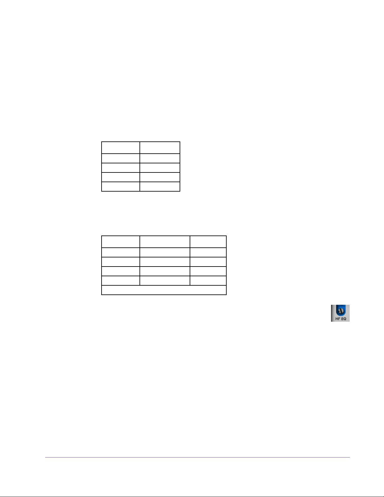
11. Increase Bias (clockwise) until the meter level is reduced by –3.5 dB from
its maximum (for 3.5 dB of overbias; see Manual Calibration Notes).*
*When calibrating at 3.75 or 7.5 IPS, the tone generator is at a lower level, therefore meter resolution is decreased. To increase meter precision when adjusting bias at the lower tape speeds, consider temporarily increasing the reproduce level.
Record Level Calibration
Record EQ Calibration
12. Set the Tones frequency to 1 kHz.
13. Adjust Record (input) so the Meters display the level in Table 4 below (the
level depends on tape speed).
Table 4. Meter Levels for Record and HF EQ Adjustments
Tape Speed Meter Level
3.75 IPS –20 dB
7.5 IPS –10 dB
15 IPS 0 dB
30 IPS 0 dB
14. Set the Tones frequency to the value in Table 5 below (the frequency de-
pends on tape speed).
Table 5. Record HF EQ Calibration Frequencies and Levels
Tape Speed Tone Frequency Tone Level
3.75 IPS 5 kHz* –16 dB
7.5 IPS 10 kHz –6 dB
15 IPS 15 kHz +4 dB
30 IPS 20 kHz +4 dB
*Note: 7.5 kHz is specified in Ampex manual.
15. Adjust Record HF EQ (not to be confused with Repro HF) so the
Meters display the level in Table 4 above (the level depends on tape
speed).
Note: If HF EQ is adjusted by a large amount, it may be necessary to reca-
librate the record level (steps 12, 13).
The manual calibration procedure is complete.
For related information, see the Manual Calibration Notes in the next section.
UAD Powered Plug-Ins Manual - 41 - Chapter 2: Ampex ATR-102
Page 42

Manual Calibration Notes
• 0 dB on the output meter represents +4 dBm (and –12 dBFS digital) when
Reproduce is in its calibrated position, which is marked with the “red arrow
sticker.”
• For proper calibration, follow the entire calibration procedure in order.
• This example uses 3.5 dB overbias. The amount of gain reduction in step 12
determines the amount of overbias. In some cases we used more than
3.5 dB of overbias to achieve a flatter response.
• Generally speaking, higher Cal Level values will have higher Distortion
Meter values for a given reading on the Meters. If Bias is set very low, dis-
tortion may increase at lower Cal Levels.
• We recommend leaving the record SHELF EQ control in its default position.
• The Ampex ATR-102 hardware has an additional gain control via a set-
screw (like Repro HF/LF, Bias, etc) which is usually used for manual gain
calibrations. This control is not available in the plug-in because it would be
redundant – the Reproduce control performs the same function.
• We chose to calibrate our reference machine using MRL fringing-compen-
sated calibration tapes, without later adjusting the Repro LF EQ for unity
gain using external test tones. Therefore the calibrated values in the plug-in
reflect this alignment method. In-depth discussions about fringing compensation and system alignment are beyond the scope of this manual; thorough
resources are available from the MRL website at: http://www.mrltapes.com
• Tape Type 111 uses a calibration level of 0 dB. This value is not available
in the plug-in, but it can be emulated by setting the CAL level to +3 dB, then
reducing the input level (Record knob) by –3 dB and increasing the output
level (Reproduce knob) by +3 dB.
• The plug-in operates at an internal level of –12 dBFS. Therefore a digital sig-
nal with a level of –12 dB below full scale digital (0 dBFS) at the plug-in input will represent 0 dB on the plug-in meters (if the plug-in is calibrated).
• The included artist presets demonstrate how manual calibration can be
used to obtain sonic variations (see “Artist Presets” on page 22).
Tip: For easy recall in future sessions, save unique calibrations as a preset.
UAD Powered Plug-Ins Manual - 42 - Chapter 2: Ampex ATR-102
Page 43
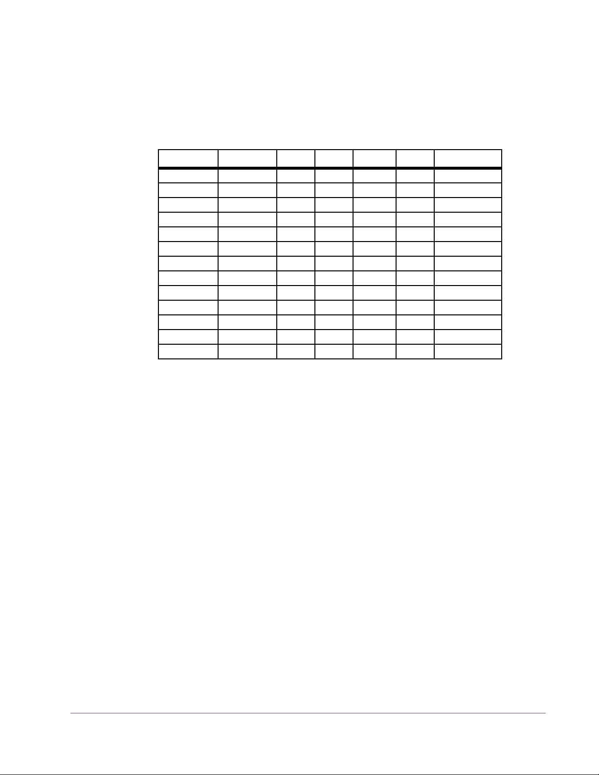
Parameter Dependencies
Available Settings
Some ATR-102 parameter value ranges depend on the value of other parameters. These dependencies are listed in Table 6 below.
Table 6. Ampex ATR-102 parameter dependencies
Tape Speed Head Width Tape 1 Tape 2 Tape 3 Tape 4 Emphasis EQ
30 IPS 1” 250 456 468 GP9 AES
30 IPS 1/2” 250 456 900 GP9 AES
30 IPS 1/4” 250 456 900 GP9 AES
15 IPS 1” 250 456 468 GP9 NAB
15 IPS 1” 250 456 468 GP9 CCIR
15 IPS 1/2” 250 456 900 GP9 NAB
15 IPS 1/2” 250 456 900 GP9 CCIR
15 IPS 1/4” 250 456 900 GP9 NAB
15 IPS 1/4” 250 456 900 GP9 CCIR
7.5 IPS 1/4” 250 456 35-90 111 NAB
7.5 IPS 1/4” 250 456 35-90 111 CCIR
3.75 IPS 1/4” 250 456 35-90 111 NAB
3.75 IPS 1/4” 250 456 35-90 111 CCIR
Ampex ATR-102 Latency
The Ampex ATR-102 uses an internal upsampling technique. This upsampling
results in a larger latency than most other UAD plug-ins. See “UAD Delay
Compensation” in the UAD System Manual for more information.
UAD Powered Plug-Ins Manual - 43 - Chapter 2: Ampex ATR-102
Page 44

UAD Powered Plug-Ins Manual - 44 - Chapter 2: Ampex ATR-102
Original Ampex ATR-102 Mastering Recorder Brochure
Page 45

CHAPTER 3
API 500 Series EQ Collection
Introduction
The 550A and 560 modular EQs are some of the most popular and enduring
mixing and tracking processors ever made. The 500 series modules from API
are true industry standards, found in professional multi-channel consoles to
Lunchbox racks in the humblest of project studios. Designed by the now legendary Saul Walker in the late 60s, the combination of Walker's 2520 op
amp and his Proportional Q circuitry gave the 550 and 560 an uncomplicated way to generate acoustically superior equalization.
Universal Audio now offers the UAD-2 platform true best-in-class emulations of
these two audio production staples. With UA’s industry-leading circuit modeling that captures the filter shapes, band interactions, and unique filter amplifier clipping behaviors providing full “suspension of disbelief,” these plugins
fulfill sonic requirements that previously only the API hardware could provide.
Based on vintage units provided by Ross Hogarth and Capitol Studios, both
plug-ins provide era-specific features and behaviors, and a remarkable model
of API’s custom 2520 and output transformer — the results are fantastic lowfrequency transparency and tight imaging, which is that legendary API
“punch in your gut” sound. Like with the hardware, the EQs are extremely fast
to set, reliable and uniform, and deliver that one-of-a-kind API high headroom
precision.
If you want the sound of classic American music, you need the API EQs.
UAD Powered Plug-Ins Manual - 45 - Chapter 3: API 500 Series EQ Collection
Page 46

API 500 Series EQ Collection Screenshots
Figure 5. The API 550A EQ (left) and API 560 EQ (right) plug-in windows
UAD Powered Plug-Ins Manual - 46 - Chapter 3: API 500 Series EQ Collection
Page 47

Operational Overview
API 500 Series Collection
The API 500 Series EQ Collection includes the UAD API 550A and UAD API
560 plug-ins, which are officially licensed from and endorsed by Automated
Processes Inc. Both plug-ins meticulously model the entire electronic path, including custom API 2520 op-amps, transformers, band interactions, and internal clipped filter nonlinearities.
API 550A The API 550A provides reciprocal equalization at 15 points in five steps of
boost or cut to a maximum of ±12 dB of gain at each point. The fifteen fixed
equalization points are divided into three overlapping band ranges. The high
and low frequency bands are individually selectable to function as either
peaking or shelving filters. A bandpass filter may be inserted independently
of all other selected equalization settings.
API 560 The 10 precision EQ bands make the 560 ideal for signal sweetening and
mix tuning. The boost and cut characteristics are identical, allowing previous
actions to be undone if desired.
Proportional Q The 550A and 560 filters feature API’s “Proportional Q” which continuously
narrows the bandwidth of the filter as band gain is increased, providing (as
stated by API) “an uncomplicated way to generate acoustically superior
equalization.”
Artist Presets The API 500 Series EQ Collection includes artist presets from prominent API
users. The artist presets are in the internal factory bank and are accessed via
the host application’s preset menu. The artist presets are also copied to disk
by the UAD installer so they can be used within Apollo’s Console application.
The presets can be loaded using the Settings menu in the UAD Toolbar (see
“Using UAD Powered Plug-Ins” in Chapter 7 of the UAD System Manual).
API 500 Series Latency
These plug-ins use an internal upsampling technique to achieve sonic design
goals. The upsampling results in a slightly larger latency than most other UAD
plug-ins. See Chapter 9 “Delay Compensation” in the UAD System Manual
for more information.
UAD Powered Plug-Ins Manual - 47 - Chapter 3: API 500 Series EQ Collection
Page 48
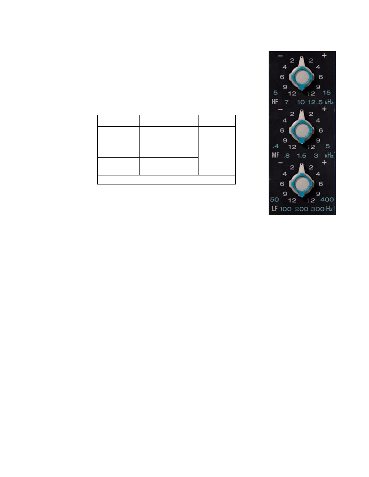
API 550A Controls
Band Controls The three EQ bands (HF/MF/LF) are controlled by
dual-concentric switches. The inner knob controls the
band frequency and the outer knob controls the band
gain. Available values for these controls are listed in
Table 7 below.
Table 7. API 550A Frequency and Gain Values
Band Frequency Values Gain Values
High Frequency
(HF)
Mid Frequency
(MF)
Low Frequency
(LF)
Frequency
5, 7, 10, 12.5, 15
(kHz)
0.4, 0.8, 1.5, 3, 5
(kHz)
50, 100, 200, 300, 400
(Hz)
Default values are in bold.
0
2
4
6
9
12
(±dB)
Frequency determines the center frequency of the
band when the filter is in peak mode and the cutoff frequency when the filter is in shelf mode. The frequency for the band can be set
using any of these four methods:
1. Drag the inner concentric knob to the desired value, or
2. Hover over the inner concentric knob then use the mouse scroll wheel, or
3. Click directly on the frequency value label to switch to that value, or
4. Click on the band label (HF/MF/LF) or units label (kHz/Hz) to cycle
through available values.
Gain
The gain for the band can be set using any of these three methods:
1. Drag the outer concentric knob handle to the desired value, or
2. Click the “+” or “–” text labels to increment/decrement values, or
3. Hover over the outer concentric knob then use the mouse scroll wheel, or
4. Click directly on the gain value label to switch to that value (this method
works only when Controls Mode is set to “Circular” in the UAD Control
Panel Configuration panel).
UAD Powered Plug-Ins Manual - 48 - Chapter 3: API 500 Series EQ Collection
Page 49

Bandpass Filter This switch (“FLTR”) applies a 50 Hz – 15 kHz bandpass filter to
the entire signal. The bandpass filter is completely independent
from the from the three main band filters.
Bell/Shelf Switches
The HF and LF bands are normally in bell mode. When the
Bell/Shelf button is engaged for the band (in the darker
“down” position), the band is switched to shelving mode.
LF Shelf
When the LF Shelf button is engaged, the low frequency band is switched to
shelving mode.
HF Shelf
When the HF Shelf button is engaged, the high frequency band is switched to
shelving mode.
Output This control provides –24 dB to +12 dB of clean uncolored gain
at the output of the plug-in.
Tip: Click the “0” text label to return Output to the 0 dB position.
EQ In The EQ In switch enables the three band filters and the bandpass filter.
All filters are active when the switch is engaged and the “IN” LED is illuminated.
When disengaged, the filters are bypassed but other hardware circuitry is still modeled.
Power The plug-in is active when the POWER switch is engaged and its
associated LED is illuminated. When this switch is off, all plug-in
processing is disabled and UAD DSP usage is reduced (unless
UAD-2 LoadLock is enabled).
UAD Powered Plug-Ins Manual - 49 - Chapter 3: API 500 Series EQ Collection
Page 50

API 560 Controls
Note: Like the original 560 hardware, the signal is boosted by approxi-
mately 1 – 1.5 dB even when all gain sliders are set to 0 dB.
Gain Sliders Each of the 10 sliders controls the gain for one fre-
quency band. Each band can be adjusted to boost or cut
the frequency by up to ±12 dB. The available band frequencies are listed in Table 8 below.
Table 8. API 560 Frequencies
16 kHz
8 kHz
4 kHz
2 kHz
1 kHz
500 Hz
250 Hz
125 Hz
63 Hz
31 Hz
Tip: To return a slider to the 0 dB position, click the
slider’s frequency text label. To reset all sliders to 0 dB,
click the “0” text label above the sliders.
Output This control provides -24 dB to +12 dB of clean uncolored gain
at the output of the plug-in.
Tip: Click the “0” text label to return Output to the 0 dB position.
EQ In The EQ In switch enables the filter sliders. The EQ bands are
active when the switch is engaged and the associated “IN”
LED is illuminated.
When disengaged, the EQ bands are bypassed but other hardware circuitry
is still modeled.
Power The plug-in is active when the POWER switch is engaged and its
associated LED is illuminated. When this switch is off, all plug-in
processing is disabled.
UAD Powered Plug-Ins Manual - 50 - Chapter 3: API 500 Series EQ Collection
Page 51

Historical Background
API (Automated Processes Inc.) was formed in 1968 with Saul Walker and
Lou Lindauer. API is perhaps most noted for their modular approach to equipment manufacturing and for their now legendary 2520 amplifier. To this day,
the extraordinary headroom made possible with the 2520 offers consistent
analog performance even when using radical EQ curves. API quickly became
the leading audio broadcast console manufacturer for radio and television
networks and high profile stations. Soon after, recording studios both large
and small began using API. The API brand and the company’s commitment to
excellent audio design endures to this day.
The 550A became API’s standard channel module EQ when the company began manufacturing consoles in 1971. As the industry rapidly embraced the
sonic quality of the 550A, it quickly found it's way into many custom console
designs by Frank DeMedio and other leading engineers. Many of these consoles are still in use today. Forty years later, the 550A remains the standard
against which other EQs are measured, and it has played a major role in the
recording industry for decades. With virtually all existing units spoken for,
popular demand for this EQ resulted in API finally resuming production in
2004.
The API 500 Series EQ Collection Original Hardware
UAD Powered Plug-Ins Manual - 51 - Chapter 3: API 500 Series EQ Collection
Page 52

CHAPTER 4
API Vision Console Channel Strip
Introduction
The API Vision Console Channel Strip plug-in for the UAD platform is based
on API’s flagship console found in studios and sound stages across the globe.
The plug-in includes five indispensable modern production API modules available in the Vision console: The custom 2520 op-amp based 212L Preamp,
215L Sweep Filters, 550L EQ, 225L Compressor/Limiter, and the 235L
Gate/Expander.
The tone of the 212L mic preamp has its roots in the classic API 2488 series
all-discrete recording consoles, best known for the famed “LA” sound. The API
212L incorporates the API 2520 op-amp and the same circuit as the legendary API console input modules dating from the 1970s. This mic preamp articulates high frequencies with great detail, while delivering the big sounding,
warm bottom end that API is famous for.
With identical features as the modern API 550B EQ, the API 550L (L for
“long” frame) is a continuation of the 550A EQs that have played a major
role in the history of record making, but with an additional filter band and several new frequencies. The 550L artfully blends the past with the present, and
is only available in modern API consoles. Making use of API's “Proportional
Q” innovation, the 550L intuitively widens the filter bandwidth at minimal settings and narrows it at higher settings without the need for additional bandwidth controls.
Ideal for almost any application, the widely versatile API 225L Compressor's
auto-output level remains at unity regardless of the threshold or ratio settings.
This feature allows for real-time adjustments without the need for changing the
output level. Both New (“feed-forward”) and Old (“feed-back”) methods are
selectable via the front panel, providing two choices of gain reduction. Soft
provides a more subtle compression resulting in a natural sound, while Hard
results in a sharp knee type with a severe limiting effect.
UAD Powered Plug-Ins Manual - 52 - Chapter 4: API Vision Console Channel Strip
Page 53

The 235L Noise Gate/Expander is one of the fastest noise gates available.
The API 235L can reduce noise in any type of program without losing any
part of the source. Its extreme flexibility and superb sound make it ideal for all
recording or mixing studio applications. The Expander function uses a 1:2 ratio, allowing the signal to “sneak up” to the full signal level without any loss
of “under threshold” vocal or percussion nuances. Setting the threshold in the
Gate function to the desired level, then switching to the Expander mode is the
perfect workflow.
The API 215L is a unique passive, sweepable cut filter, designed specifically
to contour the sound in a way that preserves the natural tone of the signal. The
215L is a low pass filter with a slope of 6 dB per octave, and a high pass filter
with a slope of 12 dB per octave. The filters are isolated from each other with
the same discrete transistor buffer used in the famous 550 series equalizers.
API Vision Console Channel Strip Screenshot
Figure 6. The API Vision Console Channel Strip plug-in window
UAD Powered Plug-Ins Manual - 53 - Chapter 4: API Vision Console Channel Strip
Page 54

Operational Overview
Modular Design Like the original hardware, the API Vision Console Channel Strip plug-in has
a modular design. Each module controls a different signal processing function, and associated controls are grouped within each module. The following
modules are contained in the API Vision Console Channel Strip plug-in:
• 212L Microphone Preamplifier
• 215L High/Low Sweep Filters
• 235L Gate/Expander
• 225L Compressor/Limiter
• 550L Four-Band Equalizer
Signal Flow A simplified view of the default signal flow routing within the plug-in is illus-
trated in the diagram below. The audio path is shown with solid lines, and the
side chain control keys for the dynamics modules are shown with dotted lines.
Figure 7. Simplified default signal flow within the API Vision Console Channel Strip
The signal flow can be re-routed via options in the plug-in. The 550L EQ can
be placed before the dynamics modules via the PREDYN (pre-dynamics) button, and the 215L and/or 550L modules can be moved out of the audio path
and into the dynamics side chain path via the SC (side chain) buttons in those
modules.
Note that the side chains for the dynamics modules are in series by default (as
in diagram above). However, when the 215L and/or 550L are moved into
the side chain (via the SC buttons), the side chain inputs for the dynamics
modules are in parallel, as shown in the diagram below.
Figure 8. Simplified signal flow illustrating parallel side chain inputs with 215L SC enabled
UAD Powered Plug-Ins Manual - 54 - Chapter 4: API Vision Console Channel Strip
Page 55

Displayed Values
Knob settings, when compared to the graphical user interface silkscreen numbers, may not match the actual parameter values. For example, in the 215L
Sweep Filters module, the highest value shown in the plug-in window is 20
kHz. However, the actual value when the knob is at maximum is 40 kHz.
This behavior is identical to the original hardware, which is modeled exactly.
When the plug-in is viewed in parameter list mode (controls and/or automation views), the actual parameter values are displayed.
Artist Presets The API Vision Console Channel Strip includes artist presets from prominent
API users. The artist presets are in the internal factory bank and are accessed
via the host application’s preset menu. The artist presets are also placed by
the UAD installer so they can be used within Apollo’s Console application.
The presets can be loaded using the Settings menu in the UAD Toolbar (see
“Using UAD Powered Plug-Ins” in Chapter 7 of the UAD System Manual).
This plug-in includes additional artist presets that are not available in the internal factory bank. These additional presets can also be accessed using the
Settings menu in the UAD Toolbar.
Unison™ Integration
The API Vision Console Channel Strip features Unison mic preamp
technology integration with the mic preamp hardware in Universal
Audio’s Apollo audio interfaces. With Unison, Apollo’s ultra-transparent mic preamps inherit all the unique sonic and input characteristics of the
API Vision 212L hardware preamp module.
Realistic Tandem Control
Unison facilitates seamless interactive control of API Vision Console Channel
Strip plug-in settings using Apollo’s digitally-controlled panel hardware
and/or the plug-in interface. All equivalent preamp controls (gain, pad, polarity) are mirrored and bi-directional. The preamp controls respond to adjustments with precisely the same interplay behavior as the API Vision Console
Channel Strip hardware, including gain levels and clipping points.
UAD Powered Plug-Ins Manual - 55 - Chapter 4: API Vision Console Channel Strip
Page 56

Hardware Input Impedance
All Apollo mic preamps feature input impedance switching in analog hardware that can be physically switched by Unison plug-ins for physical, microphone-to-preamp resistive interaction. This impedance switching enables
Apollo’s preamps to physically match the emulated unit’s input impedance,
which can significantly impact the sound of a microphone. Because the electrical loading occurs on input, prior to A/D conversion, the realism is faithful
to the original target hardware preamp.
Tactile Gain Staging
Apollo’s front panel preamp knob can independently adjust the gain and
level parameters available within the Unison plug-in via Gain Stage Mode.
The gain stage being adjusted can be remotely switched via Apollo, so the
gain levels and their associated colorations can be tuned from the hardware
knob for precise physical tactile control, all without using the Unison plug-in’s
software interface.
Note: Unison is active only when the plug-ins are inserted in the unique
PREAMP insert within Apollo’s Console application. For complete Unison details, see the Apollo Software Manual.
API Vision Console Channel Strip Latency
These plug-ins use an internal upsampling technique to achieve sonic design
goals. The upsampling results in a slightly larger latency (55 samples; 88
samples at 176.4 and 192 kHz) than most other UAD plug-ins. See Chapter
9 “Delay Compensation” in the UAD System Manual for more information.
UAD Powered Plug-Ins Manual - 56 - Chapter 4: API Vision Console Channel Strip
Page 57

API Vision Console Channel Strip Controls
212L
Microphone
Preamplifier
212L Gain
This knob adjusts the amount of gain applied to the input
signal. The available range is 30 dB to 65 dB. The default value is 40.5 dB.
212L Pad
When enabled, the input signal level is attenuated (lowered) by 20 dB. The pad is engaged when the red indicator is lit.
Pad can be used to reduce signal levels when undesirable overload distortion is present at low preamp gain
levels.
Note: The 212L Pad is available for both the mic and
line inputs.
212L Meter
The Meter indicates the signal level at the output of the 212L preamp module.
212L Phase
The Phase (ø) button inverts the polarity of the signal. The polarity is inverted
when the green indicator is lit. Leave the button off (unlit) for normal polarity.
Unison Impedance
When API Vision Console Channel Strip is used in a PREAMP insert
within the Apollo Console application, the hardware input impedance of the Apollo mic preamp is switched to 1.5k Ω (the value of
the 212L hardware module) for physical, microphone-to-preamp resistive interaction.
UAD Powered Plug-Ins Manual - 57 - Chapter 4: API Vision Console Channel Strip
Page 58

215L High/Low Sweep Filters
The 215L offers two sweepable cut filters, one each for
low and high frequencies. The original hardware is transformer coupled and uses a passive filter circuit design for
smooth tone.
215L Lo-Pass
The Lo-Pass (high cut) filter has a continuous range of 643
Hz to 40.8 kHz. The slope of this filter is 6 dB per octave.
The default value is 40 kHz.
215L Hi-Pass
The Ho-Pass (low cut) filter has a continuous range of 12
Hz to 596 Hz. The slope of this filter is 12 dB per octave.
The default value is 12 Hz.
215L SC (Dynamics Side Chain)
This button enables the side chain function for the 215L Sweep Filters. When
the 215L side chain is active, signal output from the 215L module is removed
from the audio path, and is instead routed to control the 235L and 225L dynamics modules in parallel as shown in the diagram below.
Figure 9. Signal flow with 215L Sweep Filters SC enabled
To listen to the side chain key, simply disengage SC to hear the equalized signal.
Note: The 215L module must be enabled for the 215L side chain to function.
215L On
This button enables the 215L module. The module is active when the button’s
green indicator is lit.
Note: UAD DSP load is reduced when this module is inactive (unless DSP
LoadLock is enabled).
UAD Powered Plug-Ins Manual - 58 - Chapter 4: API Vision Console Channel Strip
Page 59

235L Gate/Expander
The 235L Gate/Expander module operates in either gate
or expansion mode. Two attack speeds and a continuously variable release time are available in both modes.
235L Threshold
Threshold defines the input level at which expansion or
gating occurs. The available range is from +25 dB to -45
dB. The default value is 0 dB.
Signals below the threshold level are processed by the
module. Signals above the threshold are unaffected. Rotate this control clockwise to increase the gate/expand
effect.
235L Depth
Depth controls the difference in gain between the gated/expanded and nongated/expanded signal. Higher values increase the attenuation of signals below the threshold. When set to zero, no gating or expansion occurs. The
available range is 0 dB to -80 dB. The default value is -80dB.
Scaled Control
Although the Depth control has a full range of -80 dB, the scale is expanded
in the first half of rotation so 0 to -9 dB is available for fine tuning of subtle,
undetectable gating. The second half of rotation is from -10 to -80 dB for more
drastic noise reduction.
235L Attack
This two-position switch determines how quickly the onset of gating/expansion occurs when the signal exceeds the threshold. Normal (25 milliseconds) and Fast (100 microseconds) settings are available. The default setting is Normal.
235L Release/Hold Knob
The function of Release/Hold knob (R/H) depends on the setting of the Release/Hold switch (Rel/Hld). With both switch settings, the available range of
the knob is 50 milliseconds to 3 seconds. The default value is 0.5 seconds.
Note: Hold mode is only available when the 235L module is set to Gate
mode with the Gate/Expander switch.
UAD Powered Plug-Ins Manual - 59 - Chapter 4: API Vision Console Channel Strip
Page 60

Release
When the input signal drops below the threshold level and the Release/Hold
switch is set to Release, this knob sets the amount of time it takes for signals
to decay to the Depth level.
Slower release times can smooth the transition that occurs when the signal
dips below the threshold, which is especially useful for material with frequent
peaks.
Fast release times are typically only suitable for certain types of percussion
and other instruments with very fast decays. Using fast settings on other
sources may produce undesirable results.
Hold
When the input signal drops below the threshold level and the Release/Hold
switch is set to Hold, this knob sets the amount of time that signals are held at
normal levels before signals return to the Depth level.
Note: When set to Hold, the release time is fixed at 100 milliseconds.
235L Release/Hold Switch
This two-position switch (REL/HLD) determines the behavior of the Release/Hold knob when the 235L module is set to Gate mode with the
Gate/Expander switch. The default value is Release.
Note: This switch is locked in the Release position when the module is in
Gate mode (Hold mode is unavailable in Expander mode).
235L Gate/Expander Switch
This switch (GTE/EXP) toggles the module between Gate and Expander
modes. The default value is Expander.
GTE
When set to Gate mode, signals below the threshold are attenuated by the
Depth amount.
EXP
When set to Expander mode, the gate applies downwards expansion at a
fixed 1:2 ratio, with the amount of gain reduction determined by the Depth
control.
UAD Powered Plug-Ins Manual - 60 - Chapter 4: API Vision Console Channel Strip
Page 61

Expansion allows the signal to “sneak up” to the full signal level without any
loss of “under threshold” nuances.
235L Meter
This meter displays, in dB, the amount of gain attenuation (downward
expansion) occurring in the 235L module.
235L On
This button enables the 235L module. The module is active when the button’s
green indicator is lit.
Note: UAD DSP load is reduced when this module is inactive (unless DSP
LoadLock is enabled).
225L Compressor/ Limiter
The 225L Compressor/Limiter offers a continuously variable ratio between 1:1 (no compression) and infinity:1
(limiting). Three attack speeds and continuously variable
release times are available. A hard/soft knee setting and
a unique new/old setting are also available in the module.
225L Threshold
Threshold defines the input level at which compression
begins. The available range is +10 dB to -20 dB. The default value is 0 dB.
Signals that exceed the threshold are processed by the
Ratio value. Signals below the threshold are unaffected.
Rotate this control clockwise to increase the compression
effect.
Note: The 225L compressor automatically increases makeup gain to com-
pensate for levels that are reduced during compression. However, just like the
original hardware, the plug-in’s compensated makeup gain levels are not perfectly linear.
UAD Powered Plug-Ins Manual - 61 - Chapter 4: API Vision Console Channel Strip
Page 62

225L Ratio
Ratio defines the amount of gain reduction applied to signals above the
threshold. For example, a value of 2 (expressed as a 2:1 ratio) reduces the
signal level above the threshold by half, with an input signal level of 20 dB being reduced to 10 dB.
A value of 1 yields no gain reduction. When the control is at maximum (∞),
the ratio is effectively infinity to one, yielding the limiting effect. The available
range is 1:1 to infinity. The default value is 4:1.
225L Attack
This three-position switch defines the attack time of the compressor.
Available values are Fast (2 milliseconds), Medium (18 milliseconds),
and Slow (75 milliseconds). The default value is Medium.
225L Release
Release sets the amount of time it takes for processing to cease once the input
signal drops below the threshold level. The available control range is 50 milliseconds to 3 seconds.
Note: Actual release times are program dependent.
Slower release times can smooth the transition that occurs when the signal
dips below the threshold, which is especially useful for material with frequent
peaks. However, if the release is too long, compression for sections of audio
with loud signals may extend to sections of audio with lower signals.
Fast release times are typically only suitable for certain types of percussion
and other instruments with very fast decays. Using fast settings on other
sources may produce undesirable results.
225L Knee
The knee (onset) characteristic of the compressor/limiter can be set
to Soft (SFT) or Hard (HRD) with this two-position switch. The default
value is Hard.
Soft provides a more subtle compression resulting in a very natural, less compressed sound. Hard results in a more typical, sharp knee type compression
that has a more severe limiting effect.
UAD Powered Plug-Ins Manual - 62 - Chapter 4: API Vision Console Channel Strip
Page 63

225L Type
The Type control switches the 225L compressor’s control side chain
signal to use either a feed-back (OLD) or feed-forward (NEW) design, providing two types of gain reduction. The default value is
Old.
Compressors typically have a side chain control signal based on either feedback or feed-forward designs. NEW feed-forward gain reduction is typical of
newer VCA type compressors that rely on RMS detectors for the side chain circuit. The OLD feed-back method is what most classic compressors use for the
side chain circuit.
Note: Unlike the original hardware, side chain processing via the 215L and
550L modules can be performed with this switch in the OLD position (the
hardware cannot use side chain filtering with feedback compression).
225L Meter
This meter displays, in dB, the amount of gain attenuation occurring in
the 225L module.
225L On
This button enables the 225L module. The module is active when the button’s
green indicator is lit.
Note: UAD DSP load is reduced when this module is inactive (unless DSP
LoadLock is enabled).
UAD Powered Plug-Ins Manual - 63 - Chapter 4: API Vision Console Channel Strip
Page 64

550L Four-Band Equalizer
The 550L EQ is divided into four frequency bands: High
Frequency (HF), High Midrange Frequency (HMF), Low
Midrange Frequency (LMF), and Low Frequency (LF).
The 550L features API’s “Proportional Q” which continuously narrows the bandwidth of the filter as band gain is
increased, providing (as stated by API) “an uncomplicated way to generate acoustically superior equalization.” The boost and cut characteristics are identical, allowing previous actions to be undone if desired.
Band Controls
The four EQ bands (HF/HMF/LMF/LF) are controlled by
dual-concentric switches. The inner knob controls the
band frequency (values in blue text) and the outer knob
controls the band gain (values in white text). Available
values for these controls are listed in the table below.
Table 9. API 550L Frequency and Gain Values
Band Frequency Values Gain Values
High Frequency
(HF)
Low Mid Freq
(LMF)
High Mid Freq
(HMF)
Low Frequency
(LF)
Default values indicated in bold text above.
20, 15, 12.5, 10, 7, 5,
2.5 (kHz)
12.5, 10, 8, 5, 3, 1.5
(kHz), 800 (Hz)
1000, 700, 500, 240,
180, 150, 75 (Hz)
400, 300, 200, 100,
50, 40, 30 (Hz)
0
2
4
6
9
12
(±dB)
Frequency
Frequency determines the center frequency of the band
when the band is in peak mode (all bands) and the cutoff frequency when the
band is in shelf mode (available with HF/LF bands only). The frequency for
the band can be set using any of these four methods:
• Drag the inner concentric knob to the desired value
• Hover over the inner concentric knob then use the mouse scroll wheel
• Click directly on the frequency value label to switch to that value
• Click on the band label (HF/HMF/LMF/LF) to cycle through available values (shift+click to cycle in reverse)
UAD Powered Plug-Ins Manual - 64 - Chapter 4: API Vision Console Channel Strip
Page 65

Gain
The gain for the band can be set using any of these four methods:
• Drag the outer concentric knob handle to the desired value
• Click the “+” or “-” text labels to increment/decrement values
• Hover over the outer concentric knob then use the mouse scroll wheel
• Click directly on the gain value label to switch to that value (this method
works only when Controls Mode is set to “Circular” in the Configuration
panel of the UAD Meter & Control Panel application)
Peak/Shelf Switches
The HF and LF bands are in shelf mode by default (switches in
“down” position). When the Peak/Shelf switch is engaged for the
band (in “up” position), the band is changed to peak mode. The default value is Shelf.
550L Pre-Dynamics
The Pre-Dynamics button (“PREDYN”) re-routes the 550L signal. By default, the audio signal is routed into the 550L module after dynamics processing. When PREDYN is enabled (when the green indicator is lit), this routing is swapped, and the EQ module precedes the
dynamics processors instead.
When550L PREDYN is active, the dynamics side chain is always tapped after
the 550L module, regardless of the state of the 215L module’s SC function.
Note: PREDYN has no effect when the 550L’s SC button is active.
The effect of the PREDYN button is shown in the diagrams below.
Figure 10. PREDYN routes the 550L before the dynamics modules
UAD Powered Plug-Ins Manual - 65 - Chapter 4: API Vision Console Channel Strip
Page 66

Figure 11. The 550L always precedes the side chain tap when PREDYN is active
550L SC (Dynamics Side Chain)
This control enables the side chain function for the 550L EQ. When
the 550L side chain is active, signal output from the 550L module is
removed from the audio path, and is instead routed to control the 235L and
225L dynamics modules. The default value is Off.
Figure 12. Signal flow with 550L SC enabled
Note: Both the 550L and 215L modules can both be routed simultaneously
to the dynamics side chain. In this case, the 215L precedes the 550L in the
side chain path, as shown below.
Figure 13. Signal flow with SC enabled in both 215L and 550L modules
UAD Powered Plug-Ins Manual - 66 - Chapter 4: API Vision Console Channel Strip
Page 67

550L EQ
This button enables the 550L module. The module is active
when the button’s green indicator is lit.
Note: UAD DSP load is reduced when this module is inactive (unless DSP
LoadLock is enabled).
Global Module Output Meter
The vertical LED-style metering provides a visual indication of relative signal peak levels at the output of the plugin.
SC Link (Side Chain Link)
When the plug-in is used on a stereo signal, this button
links the side chains of the left and right channels of the
225L and 235L dynamics modules so both channels are
compressed by the same amounts. SC Link is active when
the button’s green indicator is lit. The default value is enabled.
Linking the side chains prevents signals which appear on
only one channel from shifting the stereo image of the output. For example, any large transient on either channel
will cause both channels to compress, and the amount of
compression will be similar to the amount of compression
for a transient which appears on both channels at the
same time.
Note: The SC Link button cannot be engaged when the
plug-in is used in a monophonic configuration.
Output
This control provides –24 dB to +12 dB of clean uncolored gain at the output of the plug-in. The default value is
0 dB.
Tip: Click the “0” text label to return Output to the 0 dB
position.
UAD Powered Plug-Ins Manual - 67 - Chapter 4: API Vision Console Channel Strip
Page 68
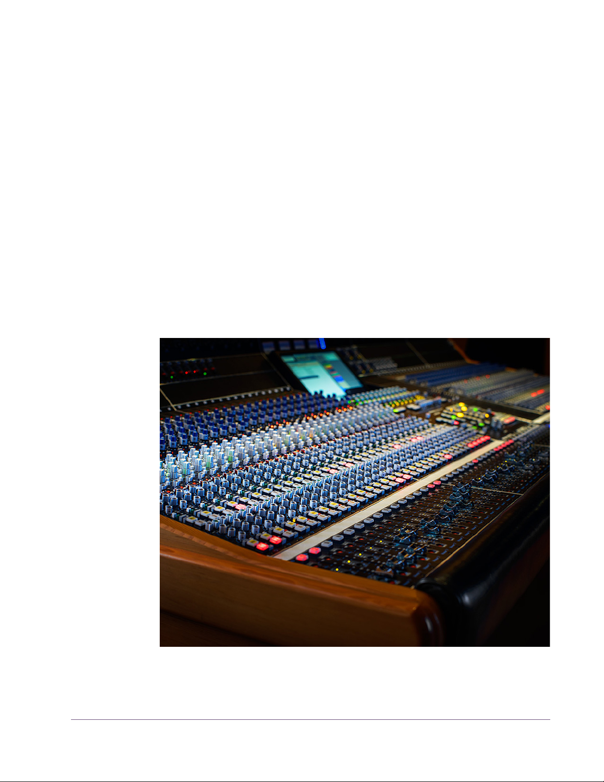
Power
The plug-in is active when the POWER switch is engaged and its associated
LED is lit. When this button is off, all plug-in processing is disabled and UAD
DSP usage is reduced (unless DSP LoadLock is enabled).
Historical Background
API (Automated Processes Inc.) was formed in 1968 with Saul Walker and
Lou Lindauer. API is perhaps most noted for their modular approach to equipment manufacturing and for their now legendary 2520 amplifier. To this day,
the extraordinary headroom made possible with the 2520 offers consistent
analog performance even when using radical EQ curves. API quickly became
the leading audio broadcast console manufacturer for radio and television
networks and high profile stations. Soon after, recording studios both large
and small began using API. The API brand and the company’s commitment to
excellent audio design endures to this day.
The API Vision Console
UAD Powered Plug-Ins Manual - 68 - Chapter 4: API Vision Console Channel Strip
Page 69

CHAPTER 5
Cambridge EQ
Overview
The UAD Cambridge EQ plug-in is a mastering-quality, no-compromise equalizer that enables powerful tonal shaping of any audio source. Its algorithm
was modeled from various high-end analog filters, providing a sonically rich
foundation for timbral manipulation. Special attention was given to the handling of higher frequencies, resulting in a much smoother and more satisfying
high-end response than is found in most digital filters.
Cambridge EQ is highly flexible, offering a broad spectrum of options facilitating surgical precision and delivering superior aural results in every application. This may be the most satisfying, full-featured equalizer in your arsenal
of creative tools.
Cambridge EQ Screenshot
Figure 14. The UAD Cambridge EQ plug-in window
UAD Powered Plug-Ins Manual - 69 - Chapter 5: Cambridge EQ
Page 70

Cambridge EQ Controls
Each feature of the Cambridge EQ interface is detailed below.
Response Curve Display
The Response Curve Display plots the frequency response of the current Cambridge EQ settings. It provides instant visual feedback of how audio is being
processed by the equalizer.
Figure 15. Cambridge EQ Response Curve display
The entire audio spectrum from 20 Hz to 20 kHz is displayed along the horizontal axis. Gain and attenuation of frequencies (up to ±40 dB) are displayed along the vertical axis. The vertical resolution of this display can be
modified with the Zoom buttons.
Response Curve Color
The color of the response curve depends on the value of the A/B Selector control. When A is active, the curve is yellow. When B is active, the curve is
green (see “A/B Selector Button” on page 72). When Cambridge EQ is disabled, the response curve is grey.
UAD Powered Plug-Ins Manual - 70 - Chapter 5: Cambridge EQ
Page 71

Zoom Buttons The vertical scale of the Curve Display can be increased or reduced with the
Zoom buttons. This function allows the resolution of the Curve Display to be
changed for enhanced visual feedback when very small or very large
amounts of boost or cut are applied. Four vertical ranges can be selected with
the Zoom buttons: ±5, ±10, ±20, and ±40 dB.
Figure 16. Vertical resolution of the Response Curve can be changed with the Zoom buttons
Curve Control Bats
There are five control “bats” on the curve display. Each bat is color coded
and corresponds to each of the five EQ bands. The position of the bat on the
curve display reflects the frequency and gain of its corresponding band, even
if the band is disabled.
Figure 17. The Curve Control Bats can be used to control EQ band frequency, gain, and Q
The gain and frequency of an EQ band can be modified simultaneously by
dragging its bat with the mouse. If a band is disabled when its bat is touched
for the first time, the band is enabled.
Note: To modify the Q of a band with its bat, hold down the Control key while
dragging vertically.
When a band is enabled, the EQ curve usually touches the bat. However, because the EQ curve always displays the actual frequency response of Cambridge EQ, if two bands are close together in frequency and/or at extreme
gain values, the bat may not touch the curve itself.
UAD Powered Plug-Ins Manual - 71 - Chapter 5: Cambridge EQ
Page 72

Master Level Knob
This control adjusts the signal output level of Cambridge EQ. This
may be necessary if the signal is dramatically boosted or reduced by the EQ settings. The available range is ±20 dB.
A/B Selector Button
EQ Enable Button
The A/B Selector switches between two separate sets of Cambridge EQ plug-in values. This feature enables easy switching
between two completely independent EQ curves which can be
useful for comparison purposes or for automating radical timbre changes. Both the A and B curves reside within a single
Cambridge EQ preset.
Click the A/B Selector button to switch between the two curves. When A is
displayed, the button and the EQ response curve is yellow. When B is displayed, the button and the curve is green.
Note: To reset the A or B curve to a null (flat) response, control-click the A/B
Selector button. The active curve will be nulled.
Note: To copy one curve to another, shift-click the button. The active curve will
be copied to the inactive curve.
This button enables or disables the Cambridge EQ altogether. You can use this switch to compare the processed
settings to that of the original signal, or to bypass the plugin to reduce UAD DSP load (load is not reduced if UAD-2
DSP LoadLock is enabled).
UAD Powered Plug-Ins Manual - 72 - Chapter 5: Cambridge EQ
Page 73

Low Cut / High Cut Filters
The Low Cut and High Cut filters are offered in addition to the five parametric/shelf bands. A wide
range of filter types is provided to facilitate tonal
creativity. Many filters that are available are represented.
Three controls are offered: Cut Type, Enable, and
Frequency. Each control is detailed below.
Cut Type Menu The Cut Type menu determines the sound of the low
and high cut filters. To view the Cut Type menu, click
and hold the green cut type button.
Four types of responses are provided: Coincident
Pole, Bessel, Butterworth, and Elliptic. The numbers
represent the filter order, i.e. Bessel 4 is a fourth-order filter. Each offers a different sound. To select a
new cut response, drag to the desired response and
release.
Cut Enable Button
The responses are more gentle on filters with lower
numbers, and get steeper and more aggressive as
the numbers increase. The coincident-pole filters are
first-order filters cascaded in series and offer gentle
slopes. Bessel filters are popular because of their
smooth phase characteristic with decent rejection. Butterworth filters offer
even stronger rejection. The Elliptic setting is about as “brick wall” as you can
get. Generally speaking, more phase shifting occurs as the response gets
steeper.
Note: UAD DSP usage does increase some as the filters get stronger (unless
UAD-2 DSP LoadLock is enabled).
This button activates the cut filters. The filters are enabled when the “In” button
is green. UAD DSP usage is slightly reduced when the cut filters are disabled
(unless UAD-2 DSP LoadLock is enabled).
UAD Powered Plug-Ins Manual - 73 - Chapter 5: Cambridge EQ
Page 74

Cut Frequency Knob
EQ Bands
This knob determines the cutoff frequency for the Cut filters. The available
range is from 20 Hz – 5 kHz for the low cut filter, and 20 Hz – 20 kHz for
the high cut filter.
All five of the EQ bands can be used in parametric or shelf mode. Each band
has identical controls, the only difference is the frequency range values.
The function of the controls is similar in both parametric and shelf modes. The
two modes are described separately (see “Parametric EQ” on page 75 and
“Shelf EQ” on page 78).
Figure 18. The EQ Band controls
Enable Button Each band can be individually engaged with the Enable button. The button is
green when the band is enabled. All bands default to disabled. To enable
any band, click the Enable button.
You can use these buttons to compare the band settings to that of the original
signal, or to bypass the individual band. UAD DSP usage is slightly decreased when a band is disabled (unless UAD-2 DSP LoadLock is enabled).
Frequency Knob This parameter determines the center frequency to be boosted or attenuated
by the Gain setting. The available range for each of the five bands is the same
for both parametric and shelf modes. The ranges are shown in Table 10 on
page 75.
UAD Powered Plug-Ins Manual - 74 - Chapter 5: Cambridge EQ
Page 75

Table 10. Available ranges for the Band Frequency parameter
Low Frequencies (LF) 20-400 Hz
Low-Mid Frequencies (LMF) 30-600 Hz
Mid Frequencies (MF) 100-6 kHz
High-Mid Frequencies (HMF) 900-18 kHz
High Frequencies (HF) 2k-20 kHz
Note: When operating at sample rates less than 44.1 kHz, the maximum fre-
quency will be limited.
Gain Knob This parameter determines the amount by which the frequency setting for the
band is boosted or attenuated. The available range is ±20 dB.
Q (Bandwidth) Knob
Parametric EQ
Parametric Type Selector
The behavior of the Q parameter varies depending on the band mode and
the gain. For this reason Q is detailed separately in the parametric and shelf
mode sections (see “Parametric Q” on page 75 and “Shelf Q” on page 78).
A band is in parametric mode when shelf mode is disabled (see “Shelf Enable
Button” on page 78). Three types of parametric EQ are available, as deter-
mined by the Parametric Type selector.
The Parametric Type selector changes the response of the band
controls to reflect the behavior of various analog equalizers. It is
a global control for all 5 bands, and has no effect on the low
and high cut filters. Click the Parametric Type display to rotate between Types
I, II, and III.
The filter algorithm is the same in all three parametric types. The difference is
in the dependency between the gain and Q parameters. Each parametric
type has its own response characteristics.
In Type I mode, the Q remains constant regardless of the gain setting. In Type
II mode, the Q increases as gain is boosted, but remains constant as gain is
attenuated. In Type III mode, the Q increases as gain is boosted and attenuated. See Figure 19, Figure 20, and Figure 21.
Parametric Q The Q (bandwidth) knob sets the proportion of frequencies surrounding the
center frequency to be affected by the gain control. The Q range is 0.25–16;
higher values yield sharper slopes.
UAD Powered Plug-Ins Manual - 75 - Chapter 5: Cambridge EQ
Page 76
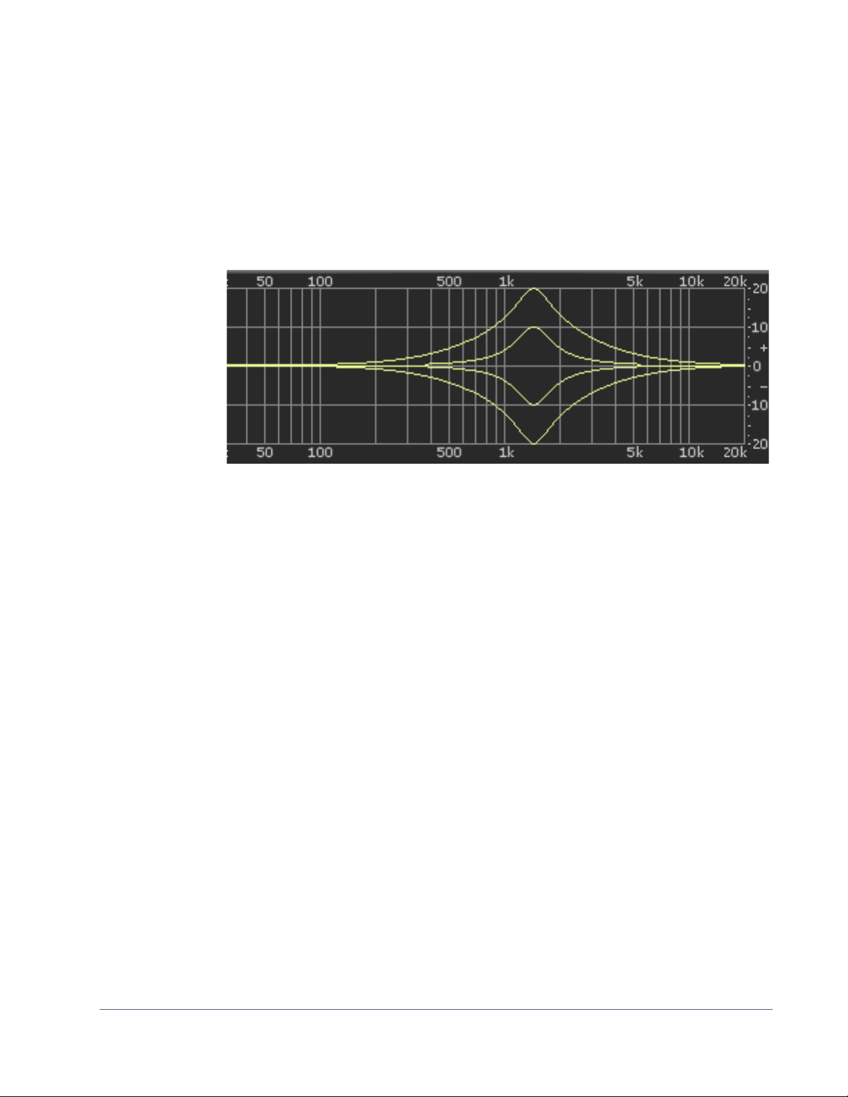
Note that the Q numeric value in relation to its knob position is warped (i.e.
not linear) and varies according to the parametric type.
Type I When set to Type I, the bandwidth remains at a fixed Q regardless of the gain
setting for the band; there is no Q/Gain interdependency. In addition, there
is a finer resolution of the Q knob in the middle of its range. This makes it easier to achieve subtle bandwidth changes. Note that the Q value and knob positions do not change as the gain is modified. See Figure 19
Figure 19. Parametric Type I response
.
Type II When set to Type II, there is a Q/Gain dependency on boost. The bandwidth
increases continuously as the gain is boosted, but not when attenuated. The
Q knob position determines the maximum Q at full gain.
Filter bandwidth is broader at lower boost settings and narrower at higher
boost settings. This can produce a smoother, more natural response when
boosting filter gain.
UAD Powered Plug-Ins Manual - 76 - Chapter 5: Cambridge EQ
Page 77

Note that the Q value increases as gain is boosted but the knob position does
not change The Q value is approached as gain increases, and reaches the
knob position at maximum gain. See Figure 20.
Figure 20. Parametric Type II response
Type III When set to Type III, there is a Q/Gain dependency on boost and attenua-
tion. The bandwidth increases continuously as the gain is boosted and attenuated. The Q knob position determines the maximum Q at full gain.
Filter bandwidth is broader at lower gain settings and narrower at higher
gain settings. This can produce a smoother, more natural response when adjusting filter gain.
Note that the Q value increases as gain is increased but the knob position
does not change The Q value is approached as gain increases, and reaches
the knob position at maximum gain. See Figure 21.
Figure 21. Parametric Type III response
UAD Powered Plug-Ins Manual - 77 - Chapter 5: Cambridge EQ
Page 78

Shelf EQ
Shelf Enable Button
Shelf Type Button
Each band can be switched from parametric mode to shelf
mode by clicking the shelf enable button. The button is off
by default. To enable shelving on any band, click the shelf
button.
The button is green when shelving is enabled. Additionally,
the control bat associated with the band has a horizontal
shelf indicator line in the response curve display (see
Figure 23 on page 79) when shelf mode is active.
When a band is in shelf mode and its Q is above the minimum value, a resonant peak occurs in the filter response.
The Shelf Type button affects where this resonant peak occurs in relation to the shelf frequency.
Its purpose is to emulate the response curves of classic highend analog mixing consoles. It’s yet another tool to help
you find the exact sound you are looking for.
The Shelf Type button places the resonant peak at (A) the edge of the stopband (Figure 22 on page 79), (B) the edge of the passband (Figure 23), or
(C) at the edge of the stopband and the passband (Figure 24).
Shelf Q When a band is in shelf mode, the Q knob sets the resonance of the band.
The range of the Q knob is 0-100% when in shelf mode.
Note: When a band is in shelf mode, the Gain setting will affect the Q of the
band.
When the Q is at its minimum value, there is no resonant peak. The resonance
increases and becomes more prominent as the Q is increased. Therefore, for
the shelf type to have any effect the Q must be above its minimum value.
Note: In order for this button to have any affect, the band must be in shelving
mode, some gain must be applied, and the Q must be above its minimum
value.
UAD Powered Plug-Ins Manual - 78 - Chapter 5: Cambridge EQ
Page 79
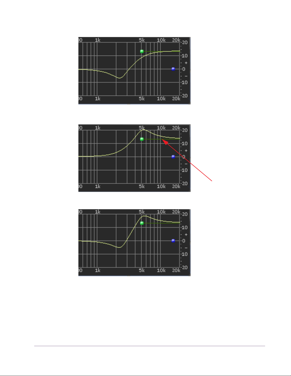
Figure 22. Shelf Type A
Shelf Mode
Indicator Line
Figure 23. Shelf Type B
Figure 24. Shelf Type C
UAD Powered Plug-Ins Manual - 79 - Chapter 5: Cambridge EQ
Page 80

CHAPTER 6
Cooper Time Cube
Dual Mechanical Delay Line
The original Cooper Time Cube was a Duane H. Cooper and Bill Putnam collaborative design that brought a garden hose-based mechanical delay to the
world in 1971 and has achieved cult status as the most unique delay ever
made. The Cooper Time Cube is famous for its spectacular short delay and
doubling effects and its uncanny ability to always sit perfectly in the mix. However, the CTC had limited practicality as a full-featured delay; only 14, 16 or
30 ms settings were available. Over the years this quirky device has grown
a strong following and finds a home in the most prestigious studios in the
world, such as Blackbird and Sunset Sound. Top producers and engineers
such as Richard Dodd, Vance Powell and Joe Chicarelli still swear by the Cooper Time Cube for its unique character.
The Cooper Time Cube MkII has all the sound of the original delay system design and offers all the necessary features expected from a modern delay device. The distinct sound of the single or double hose Coil is preserved regardless of delay setting, and either sound is available at the flick of a switch. The
Cooper time Cube MkII also incorporates other enhanced tone shifting features such as the Color switch that presents the user with the original (A) or
“leveled” (B) frequency response, plus tone controls and a 2-Pole High Pass
Filter. Lastly, a switch is presented for soloing the Wet signal, and the Send
switch disables the signal being sent into the delay processor.
Cooper Time Cube Screenshot
Figure 25. The UAD Cooper Time Cube plug-in window
UAD Powered Plug-Ins Manual - 80 - Chapter 6: Cooper Time Cube
Page 81

Design Overview
The original UREI/Universal Audio Model 920-16 Cooper Time Cube hardware (see “Cooper Time Cube Hardware” on page 85) has two audio channels, A and B. Each channel is transduced to/from a coiled length of plastic
tubing which provides the acoustic “sound columns” that define its distinctive
sonic character.
The coils for each channel are at fixed but different lengths, which define the
available single delay times of 16ms for channel A and 14ms for channel B.
The two channels can be cascaded in series via external routing, for a total
available delay time of 30ms at reasonable fidelity for its era, which (according to the original product brochure) “brings complete respectability to the
heretofore marginally feasible acoustical delay line.”
The UAD Cooper Time Cube plug-in has all the vibe of the original, with modern feature enhancements. It is a true stereo plug-in with two independent delay processors. Each channel has its own set of controls, and there are global
controls that affect the plug-in overall.
Cooper Time Cube Controls
Global Controls The global controls affect both channels of the processor simultaneously.
Figure 26. The global controls (Wet Solo and Power, also global controls, are not shown here)
Gain Gain controls the signal input level to the plug-in for both A (left) and B (right)
channels. Gain affects the combined wet and dry signals.
The available range is ±15 dB and the 12 o'clock position is unity gain.
UAD Powered Plug-Ins Manual - 81 - Chapter 6: Cooper Time Cube
Page 82

HP Filter The 12 dB per octave high pass filter is used to reduce low frequencies at the
input to the delays when desired. The high pass filter affects the delayed (wet)
signals only. The available frequency range is from 20 Hz to 12 kHz.
Turn the knob clockwise to reduce low frequencies into the delay processors.
Full processor bandwidth is obtained with the knob in the fully counter-clockwise position.
Echo A/B These two “windows” display the current delay times of channels A and B.
Displayed values are defined by the Delay parameter (“Delay A/B” on
page 84). Delay values can be entered here directly using the text entry
method.
When Sync mode is off, delay times are expressed in milliseconds. When Sync is on, delay times are expressed as a fractional bar value.
When the beat value is out of range, the value is displayed in parentheses.
This occurs in Sync mode when the time of the note value exceeds 2500ms
(as defined by the current tempo of the host application).
Sync This switch engages Sync mode for both channels of the plug-in. In Sync
mode, delay times are synchronized to (and therefore dependent upon) the
master tempo of the host application. When Sync is toggled, parameter units
are converted between milliseconds and beats to the closest matching value.
See “Tempo Sync” in Chapter 8 of the UAD System Manual for detailed information about tempo synchronization.
Send Send determines whether or not signals are sent into the delay processors.
When Send is ON, the input signals are delayed. When OFF, the delay inputs are muted.
Coils When both coiled tubes of the original hardware are cascaded to increase
the available delay time (when both channels are serially connected), the sonics are slightly different than when only one coil is used. The Coils switch toggles between these two sounds available on the hardware, regardless of the
Delay value.
Tip: Longer decays are available when Coils value is set to 1.
UAD Powered Plug-Ins Manual - 82 - Chapter 6: Cooper Time Cube
Page 83

Color The Color switch toggles between the original filter emphasis of the hardware
in position A and the “leveled” filter in position B which allows for greater Decay ranges.
Unlike the other parameters, the A and B labels for Color are for reference
only. They do not represent the left and right channels.
Note: Color can be subtle, and its affect can vary depending on the value of
Coils and/or Decay.
Treble Treble controls the high frequency response in the delayed portion of the sig-
nals. It does not affect the dry signal. Treble is a cut/boost control; it has no
effect when in the 12 o’clock position.
Bass Bass controls the low frequency response in the delayed portion of the sig-
nals. It does not affect the dry signal. Bass is a cut/boost control; it has no effect when in the 12 o’clock position.
Wet Solo The Wet Solo switch puts the Cooper Time Cube into “100% Wet”
mode. When Wet Solo is on (in the “up” position), it mutes the dry unprocessed signal.
Wet Solo is optimal when the plug-in is used on an effect group/bus that is
configured for use with channel sends. When the plug-in is used on a channel
insert, this control should be deactivated.
Note: Wet Solo is a global (per plug-in instance) control. Its value is saved
within the host project/session file, but not within individual preset files.
Power The Power switch determines whether the plug-in is active. It's useful for com-
paring the processed sound to the original signal.
Meter The VU Meter provides a visual indication of the output level of the plug-in (the
meter is not calibrated). The meter needle drops to minimum when the plug-in
is disabled with the Power switch.
UAD Powered Plug-Ins Manual - 83 - Chapter 6: Cooper Time Cube
Page 84

Channel Controls
The channel controls affect each channel of the processor independently. The
control functionality is identical for each channel. “A” indicates the left channel and “B” is the right channel.
Figure 27. The channel controls
Delay A/B Delay controls the delay time for each channel of the processor. The selected
value is shown in the Echo display (“Echo A/B” on page 82).
The available delay range for each channel is 5 milliseconds to 2.5 seconds
(2500ms). When Sync is active, beat values from 1/64 to 3/1 can be selected.
When the beat value is out of range, the value is displayed in parenthesis.
This occurs in Sync mode when the time of the note value exceeds 2500ms
(as defined by the current tempo of the host application). See “Temp Sync” in
Chapter 8 of the UAD System Manual for detailed information about tempo
synchronization.
Tip: Click the knob then use the computer keyboard arrow keys to incre-
ment/decrement beat values in Sync mode.
Decay A/B Decay sets the amount of processed signal fed back into its input (feedback).
At the minimum value, one delayed repeat is heard. Higher values (clockwise)
increase the number of repeats and intensity of the processed signal, with
“near infinite” repeats available at the maximum setting.
Pan A/B Pan sets the position of the delayed (wet) signal in the stereo field; it does not
affect the unprocessed (dry) signal.
Tip: Click the “PAN” label text to return the control to center.
Note: When the plug-in is used in a mono-in/mono-out (“MIMO”) configu-
ration, the Pan knobs do not function and cannot be adjusted.
UAD Powered Plug-Ins Manual - 84 - Chapter 6: Cooper Time Cube
Page 85

Echo Volume A/B
This control determines the volume of the delayed signal. Rotate the control
clockwise for louder echo. Up to +10 dB of gain is available at the maximum
setting. Reducing the control to its minimum value will mute the delay.
Tip: Click the “ECHO VOL” label text to mute/unmute the delayed output.
Cooper Time Cube Hardware
Figure 28. The original Cooper Time Cube hardware front panel
Figure 29. The opened acoustic module and the complete system
UAD Powered Plug-Ins Manual - 85 - Chapter 6: Cooper Time Cube
Page 86

CHAPTER 7
CS-1 Channel Strip
Overview
The CS-1 Channel Strip provides the EX-1 Equalizer and Compressor, DM-1
Delay Modulator, and RS-1 Reflection Engine combined into one plug-in. Individual effects in the CS-1 Channel Strip can be bypassed when not in use
to preserve UAD DSP use.
The CS-1 effects can also be accessed individually by using the individual
plug-ins. This is useful if you want to use the plug-ins in a different order, or if
you want to use multiple instances of the same plug-in (such as a flange routed
to a ping-pong delay with the DM-1 plug-in).
Figure 30. The CS-1 Channel Strip plug-in window
UAD Powered Plug-Ins Manual - 86 - Chapter 7: CS-1 Channel Strip
Page 87

EX-1 Equalizer and Compressor
Figure 31. The EX-1 EQ/Compressor plug-in window
The EX-1 plug-in consists of a five-band parametric EQ and compressor.
EX-1 Equalizer Controls
The Equalizer portion of the EX-1 is a five-band fully parametric EQ. Each
band has its own set of controls. The first two bands can also be enabled to
function as low-shelf or high-pass filter. Similarly, the last two bands can be
enabled to function as either a high-shelf or low-pass filter.
Band Disable Button
Each band can be individually deactivated with the Band Disable button. All
bands default to enabled (brighter blue). To disable any band, click the Disable button. The button is darker blue when the band is disabled.
You can use these buttons to compare the band settings to that of the original
signal, or to bypass the individual band.
UAD Powered Plug-Ins Manual - 87 - Chapter 7: CS-1 Channel Strip
Page 88

Gain (G) Knob The Gain control determines the amount by which the frequency setting is
boosted or attenuated. The available range is ±18 dB.
Frequency (fc) Knob
Bandwidth (Q) Knob
Enable/Bypass Switch
Determines the center frequency to be boosted or attenuated by the Gain setting. The available range is 20 Hertz to 20 kiloHertz. When operating at
sample rates less than 44.1kHz, the maximum frequency will be limited.
Sets the proportion of frequencies surrounding the center frequency to be affected. The Bandwidth range is 0.03–32; higher values yield sharper bands.
In either of the first two bands, when the Bandwidth value is at minimum the
band becomes a low-shelf filter, and at maximum the band becomes a highpass filter.
Similarly, in either of the last two bands, when the Bandwidth value is at minimum the band becomes a high-shelf filter, and at maximum the band becomes a low-pass filter.
Globally enables or disables all bands of the Equalizer. You can use this
switch to compare the EQ settings to the original signal or bypass the entire
EQ section to reduce UAD DSP load (unless UAD-2 DSP LoadLock is enabled).
Output Knob Adjusts the signal output level of the plug-in. This may be necessary if the sig-
nal is dramatically boosted or reduced by the EQ and/or compressor settings.
EX-1 Compressor Controls
Attack Knob Sets the amount of time that must elapse, once the input signal reaches the
Threshold level, before compression will occur. The faster the Attack, the more
rapidly compression is applied to signals above the Threshold. The range is
0.05 milliseconds to 100.00 milliseconds.
Release Knob Sets the amount of time it takes for compression to cease once the input signal
drops below the Threshold level. Slower release times can smooth the transition that occurs when the signal dips below the threshold, especially useful for
material with frequent peaks. However, if you set too large of a Release time,
compression for sections of audio with loud signals may extend to lengthy sections of audio with lower signals. The range is 25 milliseconds to 2500 milliseconds (2.5 seconds).
UAD Powered Plug-Ins Manual - 88 - Chapter 7: CS-1 Channel Strip
Page 89

Ratio Knob Determines the amount of gain reduction used by the compression. For exam-
ple, a value of 2 (expressed as a 2:1 ratio) reduces the signal by half, with
an input signal of 20 dB being reduced to 10 dB. A value of 1 yields no compression. Values beyond 10 yield a limiting effect. The range is 1 to Infinity.
Threshold Knob Sets the threshold level for the compression. Any signals that exceed this level
are compressed. Signals below the level are unaffected. A Threshold of 0 dB
yields no compression. The range is 0 dB to –60 dB.
As the Threshold control is increased and more compression occurs, output
level is typically reduced. However, the EX-1 provides an auto-makeup gain
function to automatically compensate for reduced levels. Adjust the Output
level control if more gain is desired.
Meter Pop-up Menu
Enable/Bypass Switch
Compressor Output Knob
EX-1M Overview
Determines whether the VU Meter monitors the Input Level, Output Level, Gain
Reduction, or Meter Off. Click the menu above the meter display to select a
different metering function.
Enables or disables the Compressor.You can use this switch to compare the
compressor settings to that of the original signal or bypass the entire compressor section to reduce UAD DSP load (unless UAD-2 DSP LoadLock is enabled).
Adjusts the signal output level of the plug-in.
The EX-1M is a monophonic version of EX-1 that enables independent left and
right EQ settings in master effects chains and allows Logic Audio users to conserve UAD DSP resources.
EX-1M requires half the processing power compared to that of EX-1 when
used on a mono audio track within Logic Audio. Therefore, EX-1M should be
used on monophonic audio tracks within Logic whenever possible to conserve
UAD resources.
UAD Powered Plug-Ins Manual - 89 - Chapter 7: CS-1 Channel Strip
Page 90
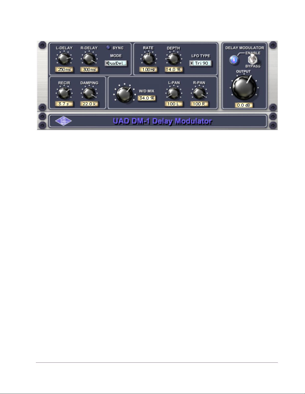
DM-1 Delay Modulator
Figure 32. The DM-1 Delay Modulator plug-in window
The DM-1 Delay Modulator provides stereo effects for delay, chorus, and
flange.
DM-1 Controls
Sync Button This button puts the plug-in into Tempo Sync mode. See Chapter 8 in the UAD
System Manual for more information.
L-Delay Knob Sets the delay time between the original signal and the delayed signal for the
left channel. When the Mode is set to one of the delay settings, the maximum
delay is 300 msec. When the Mode is set to one of the chorus or flange settings, the maximum delay is 125 msec.
R-Delay Knob Sets the delay time between the original signal and the delayed signal for the
right channel. When the Mode is set to one of the delay settings, the maximum delay is 300 msec. When the Mode is set to one of the chorus or flange
settings, the maximum delay is 125 msec.
In the flanger modes, the L and R delay controls have slightly different functions than when in the chorus modes. The high peak of the flanger is controlled by the settings of the L and R delay controls. The low Peak of the flanger
is determined by the setting of the Depth control.
When delay times longer than 300ms are desired, use the DM-1L plug-in instead. DM-1L has a maximum time of 2400ms per channel.
UAD Powered Plug-Ins Manual - 90 - Chapter 7: CS-1 Channel Strip
Page 91

Mode Pop-up Menu
Determines the DM-1 effect mode. The available modes are: Chorus,
Chorus180, QuadChorus, Flanger1, Flanger2, Dual Delay, and Ping Pong
Delay. In addition to reconfiguring the DM-1’s settings, the Mode also determines the available parameter ranges for L/R Delay and Depth.
In Chorus mode, both oscillators (or modulating signals) are in phase.
In Chorus 180 mode, both oscillators (the modulating signals) are180 degrees out of phase (inverted).
In QuadChorus mode, both oscillators (the modulating signals) are 90 degrees out of phase.
In Ping Pong delay mode, you will only get a ping-pong effect if you have a
mono source feeding the DM-1 on a stereo group track or send effect. On a
mono disk track, it works exactly like Dual Delay.
Rate Knob Sets the modulation rate for the delayed signal, expressed in Hertz.
Depth Knob Sets the modulation depth for the delayed signal, expressed as a percentage.
LFO Type Pop-up Menu
Recirculation (RECIR) Knob
In Dual Delay and Ping Pong Delay modes, adjusting the Depth and Rate controls can offer some very otherworldly sounds.
Determines the LFO (low frequency oscillator) waveshape and phase used to
modulate the delayed signal. The waveshape can be set to triangle or sine,
each with a phase value of 0, 90, or 180-degrees.
Sets the amount of processed signal fed back into its input. Higher values increase the number of delays and intensity of the processed signal.
Recirculation allows both positive and negative values. The polarity refers to
the phase of the delays as compared to the original signal. If Recirculation displays a positive value, all the delays will be in phase with the source. If it displays a negative value, then the phase of the delays flips back and forth between in phase and out of phase.
In the flanger mode, Recir has the potential to make some very interesting
sounds. Try turning RECIR fully clockwise or counter-clockwise, and set the delay to very short but different values.
UAD Powered Plug-Ins Manual - 91 - Chapter 7: CS-1 Channel Strip
Page 92

The RECIR units are expressed as a percentage in all Modes except Dual Delay and Ping Pong. In these modes, RECIR values are expressed as T60 time,
or the time before the signal drops 60 decibels.
Damping Knob This low pass filter reduces the amount of high frequencies in the signal. Turn
down this control to reduce the brightness. Higher values yield a brighter signal. Damping also mimics air absorption, or high frequency rolloff inherent in
tape-based delay systems.
Wet/Dry Mix Knob
This control determines the balance between the delayed and original signal.
Values greater than 50% emphasize the wet signal, and values less than 50%
emphasize the dry signal. A value of 50% delivers equal signals. A value of
0% is just the dry signal.
Wet/Dry Mix allows both positive and negative values. The polarity refers to
the phase of the delays as compared to the original signal. If a positive value
is displayed, then all the delays will be in phase with the source. With a negative value, the delayed signal is flipped 180 degrees out of phase with the
source.
L-Pan Knob Sets the stereo position for the left channel, allowing you to adjust the width
or balance of the stereo signal. For a mono signal, L-Pan behaves as the level
control for the left delay tap.
R-Pan Knob Sets the stereo position for the right channel, allowing you to adjust the width
or balance of the stereo signal. For a mono signal, R-Pan behaves as the level
control for the right delay tap.
Enable/Bypass Switch
Enables or disables the Delay Modulator. You can use this switch to compare
the DM-1 settings to the original signal or bypass the entire DM-1 section to
reduce UAD DSP load (load is not reduced if UAD-2 DSP LoadLock is enabled).
Output Knob Adjusts the signal output level of the plug-in.
DM-1L
DM-1L is identical to the DM-1 except that the maximum available delay time
per channel is 2400milliseconds. DM-1L requires significantly more memory
resources of the UAD than the DM-1. Therefore, we recommend using the DM1L only when very long delay times are needed.
UAD Powered Plug-Ins Manual - 92 - Chapter 7: CS-1 Channel Strip
Page 93

Link Button This button links the left and right delay knobs so that when you move one de-
lay knob, the other follows. The ratio between the two knobs is maintained.
Figure 33. The DM-1L includes a Link button
RS-1 Reflection Engine
Figure 34. The RS-1 Reflection Engine plug-in window
Overview The RS-1 Reflection Engine simulates a wide range of room shapes, and sizes,
to drastically alter the pattern of reflections. While similar to that of the
RealVerb Pro plug-in, the RS-1 does not offer the same breadth of features
(such as room hybrids, room materials, morphing, and equalization). However, if you do not need the advanced capabilities that RealVerb Pro offers,
you can use the RS-1 to achieve excellent room simulations, while also preserving DSP resources on the UAD device.
The Delay control sets the time between the direct signal and the first reflection. The Size parameter controls the spacing between the reflections. The Recir control affects the amount of reflections that are fed back to the input and
controls how many repeats you hear.
UAD Powered Plug-Ins Manual - 93 - Chapter 7: CS-1 Channel Strip
Page 94

RS-1 Controls
Sync Button This button puts the plug-in into Tempo Sync mode. See Chapter 8 in the UAD
System Manual for more information.
Shape Pop-up Menu
Determines the shape of the reverberant space, and the resulting reflective
patterns.
Table 11. Available RS-1 Shapes
Cube Square Plate
Box Rectangular Plate
Corr Triangular Plate
Cylinder Circular Plate
Dome Echo
Horseshoe Ping Pong
Fan Echo 2
Reverse Fan Fractal
A-Frame Gate 1
Spring Gate 2
Dual Spring Reverse Gate
Delay Knob Sets the delay time between the original signal and the onset of the reflec-
tions.
Size Knob Sets the size of the reverberant space (from 1–99 meters) and defines the
spacing of the reflections.
Delay/Size Settings Interaction
You may notice that when Delay is set to its maximum value and the Size control is moved to its maximum value, the Delay value is decreased, and vice
versa. This occurs because the maximum delay time available to the plug-in
has been reached — the available delay time is limited and is divided among
the Delay and Size values. Therefore, if the value of the Delay or Size setting
is increased towards maximum when the other control is already high, its
complementary setting may be reduced.
Recirculation (RECIR) Knob
Sets the amount of processed signal fed back into its input. Higher values increase the number of reverberations/delays and intensity of the processed
signal.
UAD Powered Plug-Ins Manual - 94 - Chapter 7: CS-1 Channel Strip
Page 95

Recirculation allows both positive and negative values. The polarity refers to
the phase of the delays as compared to the original signal. If Recirculation displays a positive value, all the delays will be in phase with the source. If it displays a negative value, then the phase of the delays flips back and forth between in phase and out of phase.
Damping Knob This low pass filter reduces the amount of high frequencies in the signal. Turn
down this control to reduce the brightness. Higher values yield a brighter signal. Damping also mimics air absorption, or high frequency rolloff inherent in
tape-based delay systems.
Wet/Dry Mix Knob
This control determines the balance between the delayed and original signal.
Values greater than 50% emphasize the wet signal, and values less than 50%
emphasize the dry signal.
Wet/Dry Mix allows both positive and negative values. The polarity refers to
the phase of the delays as compared to the original signal. If a positive value
is displayed, then all the delays will be in phase with the source. With a negative value, the delayed signal is flipped 180 degrees out of phase with the
source.
L-Pan Knob Sets the stereo position for the left channel, allowing you to adjust the width
or balance of the stereo signal. For a mono signal, set both the L-Pan and RPan to the left.
R-Pan Knob Sets the stereo position for the right channel, allowing you to adjust the width
or balance of the stereo signal. For a mono signal, set both the L-Pan and RPan to the left.
Enable/Bypass Switch
Enables or disables the Reflection Engine. You can use this switch to compare
the RS-1 settings to the original signal or bypass the entire RS-1 section to reduce UAD DSP load (load is not reduced if UAD-2 DSP LoadLock is enabled).
Output Knob Adjusts the relative output of the plug-in.
UAD Powered Plug-Ins Manual - 95 - Chapter 7: CS-1 Channel Strip
Page 96

CHAPTER 8
dbx 160 Compressor/Limiter
Overview
The dbx® 160 Compressor/Limiter is an officially licensed and faithful emulation of the legendary dbx 160 hardware compressor/limiter — still widely
considered the best VCA compressor ever made. Originally designed and
sold by David Blackmer in 1971, this solid-state design set the standard for
performance and affordability. The dbx 160 (commonly referred to as the
“VU”) is a highly regarded studio staple, famous for its simple control set and
firm, distinct compression characteristics. Unlike later monolithic IC units, the
“VU” uses a series of discrete components for gain reduction resulting in
unique nonlinearities not found in other VCA compressors — a sonic distinction from later models. The UAD Powered Plug-In version of the dbx 160 captures all of the sonic nuances from our “golden” modeling unit, plus the simple
control set of the original hardware, including Threshold, Compression (Ratio)
and Output Gain. Just like with the hardware, LED threshold indicators are
provided in the plug-in, as well the Input/Output/Gain Change VU meter for
which the unit is famous.
dbx 160 Screenshot
Figure 35. The dbx 160 plug-in window
UAD Powered Plug-Ins Manual - 96 - Chapter 8: dbx 160 Compressor/Limiter
Page 97

dbx 160 Controls
The minimal controls on the UAD dbx 160 make it very simple to operate.
Threshold Knob
The Threshold knob defines the level at which the onset of
compression occurs. Incoming signals that exceed the
Threshold level are compressed. Signals below the Threshold are unaffected.
The available range is from –55 dB to 0 dB. The numbers on the graphical interface indicate volts, as on the original hardware.
As the Threshold control is decreased and more compression occurs, output
level is typically reduced. Adjust the Output Gain control to increase the output to compensate if desired.
Below
When the input signal is below the compression threshold value, the Below
LED illuminates. No compression is occurring when Below is lit.
Above
The Above LED illuminates when the input signal has exceeded the Threshold
value, indicating that compression is occurring. The higher the signal is above
the Threshold, the brighter the LED glows.
Compression The Compression parameter determines the ratio for the
compressor. Less compression occurs at lower values. The
available range is continuous, from 1.00:1 to Infinity:1.
Note: For compression to occur, signals must exceed the
Threshold value.
At values above approximately 10:1, the compressor behaves more like a
peak-limiter. See “The LA-2 captures one of the earliest Teletronix examples.
This exceedingly rare unit preceded the LA-2A by a few years and incredibly,
still has the original T4A fully intact. The LA-2 provides the slowest response
and a unique “mellowed” sound due to 50 years of luminescent panel aging
UAD Powered Plug-Ins Manual - 97 - Chapter 8: dbx 160 Compressor/Limiter
Page 98

inside the T4 module. Use the LA-2 with legato tempos and your most vowellike sources for a transparency and sublime mood unlike any other compressor.” on page 470 for more information about compressor/limiter theory of
operation.
Output Gain Output Gain controls the signal level that is output from the
plug-in. The available range is ±20 dB.
Generally speaking, adjust the Output control after the desired amount of compression is achieved with the Threshold
and Compression controls. Output does not affect the
amount of compression.
Meter Buttons The Meter buttons define the mode of the VU Meter.
The buttons do not change the sound of the signal
processor. The active button has a darker appearance when compared to the inactive buttons.
VU Meter When set to Input, the VU Meter indicates the
plug-in input level in dB. When set to Output,
the VU Meter indicates the plug-in output level
in dB. When set to Gain Change, the VU Meter
indicates the amount of Gain Reduction in dB.
Power The Power switch determines whether the plug-in is active. Click the
button to toggle the state. When the Power switch is in the Off
(lighter) position, plug-in processing is disabled and UAD DSP usage is reduced (load is not reduced if UAD-2 DSP LoadLock is en-
abled).
UAD Powered Plug-Ins Manual - 98 - Chapter 8: dbx 160 Compressor/Limiter
Page 99

CHAPTER 9
DreamVerb
Overview
DreamVerb™, Universal Audio’s unique stereo reverb plug-in, draws on the
unparalleled flexibility of RealVerb Pro. Its intuitive and powerful interface lets
you create a room from a huge list of different materials and room shapes.
These acoustic spaces can be customized further by blending the different
room shapes and surfaces with one another, while the density of the air can
be changed to simulate different ambient situations.
DreamVerb also features a flexible 5-band active EQ and unique level ramping for the early and late reflections for ultra-realistic dynamic room simulation. And with Universal Audio’s proprietary smoothing algorithm, all parameters can be adjusted with automation or in real-time without distortion, pops,
clicks, or zipper noise.
DreamVerb provides two graphic menus for selecting preset room shapes.
The shapes can be blended according to the demands of your mix. Room materials are selected with two graphic menus containing preset Materials. A
third menu specifies the air density for further spectral control. As with the
room shapes, the materials and air can be blended as desired.
DreamVerb also includes intuitive graphic control over equalization, timing
and diffusion patterns. To maximize the impact of your recording, we put independent control over the direct path, early reflections, and late-field reverberation in your hands.
Capitalizing on the psychoacoustic technology that went into the design of
RealVerb Pro, we have incorporated some of these principles into DreamVerb. Our proprietary Stereo Soundfield Panning allows you to spread and
control the signal between stereo speakers creating an impression of center
and width. The ability to envelop your listener in a stereo recording is an entirely new approach to reverb design.
UAD Powered Plug-Ins Manual - 99 - Chapter 9: DreamVerb
Page 100

Screenshot
Figure 36. The DreamVerb plug-in window
Signal Flow
Figure 37 illustrates the signal flow for DreamVerb. The input signal is equal-
ized then delay lines are applied to the early reflection and late field generators. The resulting direct path, early reflection, and late-field reverberation
are then independently positioned in the soundfield.
Source
Input
Gain &
Mute
EQ
Delay
Delay
Direct Path
Early
Reflections
LateField
Reverb
Pan
Pans &
Distance
Wet/Dry
Mix
Gain
Output
Figure 37. DreamVerb signal flow
UAD Powered Plug-Ins Manual - 100 - Chapter 9: DreamVerb
 Loading...