

Page 1
UAD‑2 Live Rack
MADI Effects Processor
Operation Manual
Manual Version 180518
www.uaudio.com
Page 2

Table Of Contents
page number to jump
directly to that page.
Chapter 1: Introduction ....................................................................... 13
16-channel MADI Effects Processor For Live Mixing With UAD Plug-Ins ............................ 13
Realtime UAD Plug-In Processing .................................................................................. 13
Live Rack Application ....................................................................................................13
Fail-Safe Features ......................................................................................................... 13
UAD‑2 Live Rack Features ................................................................................ 14
Hardware ...........................................................................................................................14
Software ............................................................................................................................14
Package Contents ...............................................................................................................14
UAD‑2 Live Rack System Overview .................................................................... 15
UAD‑2 Live Rack Hardware ..................................................................................................15
Live Rack Software Application ............................................................................................15
UAD Powered Plug‑Ins ........................................................................................................15
UAD Meter & Control Panel Software Application ................................................................... 16
UAD Meter ................................................................................................................... 16
UAD Control Panels .......................................................................................................16
UA Store ............................................................................................................................ 17
Soundcraft Vi Series Consoles .............................................................................................. 17
Soundcraft Realtime Rack ...................................................................................................17
Realtime Rack Support ..................................................................................................17
Tip: Click any section or
Documentation Overview .................................................................................. 18
UAD‑2 Live Rack Manual .....................................................................................................18
UAD Plug‑Ins Manual .......................................................................................................... 18
Direct Developer Plug‑Ins ....................................................................................................18
Soundcraft Vi Series Consoles .............................................................................................. 18
Hyperlinks ..........................................................................................................................18
Technical Support ............................................................................................................... 18
Chapter 2: Hardware ........................................................................... 19
Hardware Overview ........................................................................................... 19
Front Panel ..................................................................................................... 19
(1) HOST Indicator .............................................................................................................19
(2) PSU Indicators .............................................................................................................. 20
PSU Indicator notes: ..................................................................................................... 20
(3) POWER Indicator ...........................................................................................................20
(4 & 5) MADI Indicators ...................................................................................................... 20
(4) MADI IN Indicator ...................................................................................................20
(5) MADI OUT Indicator ................................................................................................20
(6) RESET Button ............................................................................................................... 20
UAD‑2 Live Rack Manual Table Of Contents2
Page 3

Rear Panel ...................................................................................................... 21
(1) AC Power Inputs ............................................................................................................ 21
(2) Power Switches .............................................................................................................21
Automatic Failover .............................................................................................................. 21
(3) Thunderbolt 3 Ports ....................................................................................................... 22
(4) Word Clock Out .............................................................................................................22
(5) Word Clock In ................................................................................................................ 23
(6) Word Clock Termination Switch ....................................................................................... 23
(7) 1394b Ports (no function) .............................................................................................. 23
(8 & 9) MADI I/O Ports ........................................................................................................ 23
(8) MADI OUT ..............................................................................................................23
(9) MADI IN ................................................................................................................. 23
Standalone Behavior ........................................................................................ 24
Chapter 3: System Setup ..................................................................... 25
Overview ......................................................................................................... 25
System Requirements ...................................................................................... 25
If using Soundcraft Vi-Series Console .............................................................................. 25
System Connections ......................................................................................... 26
About UAD‑2 Live Rack system connections .......................................................................... 26
Single Unit Wiring ...............................................................................................................26
Cables Required (not included): .....................................................................................26
Multi‑Unit Wiring ................................................................................................................ 27
Cables Required (not included): .....................................................................................27
Thunderbolt 1 and 2 Mac Wiring .......................................................................................... 28
Additional Items Needed with Thunderbolt 1 and Thunderbolt 2 Macs ............................... 28
Thunderbolt 1 and 2 Mac Connection Notes .................................................................... 28
SoundCraft Vi‑Series Console Connections .............................................................................29
Vi-Series Console Connection Notes ................................................................................ 29
Single Unit Wiring with SoundCraft Vi Consoles .....................................................................30
Cables Required (not included): .....................................................................................30
Multi‑Unit Wiring with SoundCraft Vi Consoles ....................................................................... 31
Cables Required (not included): .....................................................................................31
Software Installation ...........................................................................................................32
Preparation ........................................................................................................................32
Software Installation Procedure ............................................................................................ 32
About Firmware Updates ...............................................................................................32
About Registration ..............................................................................................................33
About Authorization ............................................................................................................33
Authorization Procedure ......................................................................................................33
Offline Authorization Procedure ............................................................................................ 34
Operating System Software Configuration ........................................................... 36
Power Adapter and Battery Tabs ........................................................................................... 36
Required System Settings .................................................................................................... 37
UAD‑2 Live Rack Manual Table Of Contents3
Page 4

UAD‑2 Live Rack Software Configuration ............................................................ 38
Sample Rate.................................................................................................................38
Clock Source ................................................................................................................ 38
MADI Bank...................................................................................................................38
Chapter 4: Live Rack Application ......................................................... 39
Application Overview ........................................................................................ 39
Key Concepts .....................................................................................................................39
View Screens ................................................................................................................ 39
Global Displays ............................................................................................................. 40
Navigation ....................................................................................................................40
Keyboard Focus ............................................................................................................ 40
Edit & Safe Modes ........................................................................................................ 40
Offline Configuration .....................................................................................................40
Individual Channel DSP ................................................................................................. 40
Entering & Exiting the Application ........................................................................................ 41
Launch ........................................................................................................................41
Full Screen Display ....................................................................................................... 41
Hide/Switch..................................................................................................................41
Quit ............................................................................................................................. 41
Navigation Overview ......................................................................................... 43
Views Overview ...................................................................................................................43
Inserts ......................................................................................................................... 43
Gains ........................................................................................................................... 43
Delay Groups ................................................................................................................ 43
Channel ....................................................................................................................... 43
Snapshots .................................................................................................................... 43
Settings ....................................................................................................................... 43
Global Navigation Elements .................................................................................................44
Main Column ................................................................................................................ 44
Meter Bridge ................................................................................................................44
Channels Bar ................................................................................................................ 44
Info Bar .......................................................................................................................44
Banks ................................................................................................................................ 45
Current Bank ................................................................................................................ 45
Navigation Scroll Bars ........................................................................................................ 46
Keyboard Focus .................................................................................................................. 47
Focus Indication ........................................................................................................... 47
Focus Navigation .........................................................................................................47
Keyboard Shortcuts ............................................................................................................. 48
UAD‑2 Live Rack Manual Table Of Contents4
Page 5

Global Screen Elements ................................................................................... 49
View Elements .................................................................................................................... 49
Main Column ......................................................................................................................50
Column Placement ........................................................................................................ 50
View Menu ...................................................................................................................50
View Options ................................................................................................................50
Bank Views ...................................................................................................................50
Quit ............................................................................................................................. 50
Meter Bridge ......................................................................................................................51
Input Meters.................................................................................................................51
Meter Bridge Navigation ................................................................................................51
Channels Bar ......................................................................................................................52
Current Bank ................................................................................................................ 52
Bank Size.....................................................................................................................52
Bank Bar ......................................................................................................................52
Bank Navigation ...........................................................................................................52
Channel Select Buttons ................................................................................................. 53
Info Bar ............................................................................................................................. 54
Info Bar Placement ....................................................................................................... 54
Info Bar Elements ......................................................................................................... 54
Operating Mode ............................................................................................................ 55
Safe Mode Constraints ...................................................................................................56
Snapshot Display .......................................................................................................... 56
Clock Display ................................................................................................................57
Tempo Display .............................................................................................................. 58
Changing tempo values within the tempo dialog ............................................................... 58
Changing tempo values via MIDI .....................................................................................59
About external MIDI tap tempo control ............................................................................59
MIDI configuration/setup ...............................................................................................59
Resource Display ..........................................................................................................60
UAD Resource Loads ..................................................................................................... 60
DSP .............................................................................................................................61
Program ....................................................................................................................... 61
Memory ........................................................................................................................61
UAD‑2 Live Rack Manual Table Of Contents5
Page 6

Inserts View .................................................................................................... 62
Current Bank Channels ........................................................................................................ 62
Bank Size.....................................................................................................................62
Channel Column ................................................................................................................. 63
Insert Slots...................................................................................................................63
Channel Signal Flow ......................................................................................................63
State Indication ............................................................................................................ 63
Inserts Options Overview ......................................................................................................64
Option Latch ................................................................................................................64
Option Unlatch ............................................................................................................. 64
Timeout Length .............................................................................................................64
Modifiers ......................................................................................................................64
Modifier Swipe Shortcuts ............................................................................................... 64
Inserts Option Descriptions .................................................................................................. 65
Power ..........................................................................................................................66
Remove ........................................................................................................................66
Move ...........................................................................................................................66
Copy ............................................................................................................................ 67
Paste ........................................................................................................................... 67
Isolate .........................................................................................................................68
Gains View ...................................................................................................... 69
Bank View .................................................................................................................... 69
Channel Column ...........................................................................................................69
Bank Channels .............................................................................................................69
Gain Elements .................................................................................................................... 70
I/O Type .......................................................................................................................70
Gain Value ....................................................................................................................70
Gain Fader ...................................................................................................................70
Fader Handle ................................................................................................................71
Channel Number & Name .............................................................................................. 71
Link/Unlink ..................................................................................................................71
Gains Options ..................................................................................................................... 72
Inputs ..........................................................................................................................73
Outputs........................................................................................................................73
Both ............................................................................................................................ 73
Default ........................................................................................................................73
Isolate .........................................................................................................................73
UAD‑2 Live Rack Manual Table Of Contents6
Page 7

Delay Groups View ........................................................................................... 74
Bank View .................................................................................................................... 74
Channel Column ...........................................................................................................74
Bank Channels .............................................................................................................74
Delay Groups Overview ........................................................................................................75
Upsampled UAD plug-ins ...............................................................................................75
How Delay Groups work .................................................................................................75
When To Use Delay Groups ............................................................................................75
System Latency ............................................................................................................75
Delay Groups Options .......................................................................................................... 76
Delay Group Button Selectors .........................................................................................76
Compensation Menu ......................................................................................................76
Delay Groups Elements ........................................................................................................77
Active Delay Group Display ............................................................................................77
Delay Group Buttons .....................................................................................................77
Samples Display ...........................................................................................................77
Output Meter ................................................................................................................ 78
Configuring Delay Groups .....................................................................................................78
Delay Groups Example .........................................................................................................79
Channel View .................................................................................................. 80
Navigating to Channel View .................................................................................................. 80
Selecting Channels within Channel View ...............................................................................80
Two View Modes: Single View & Channel Strip View ................................................................ 81
View Mode Elements .....................................................................................................81
Switching View Modes ................................................................................................... 81
Common Elements ........................................................................................................ 81
Channel View Options ..........................................................................................................82
Channel Name Button .................................................................................................. 82
Channel Name Field ......................................................................................................82
Channel Link/Unlink ......................................................................................................82
Insert Buttons ....................................................................................................................83
Insert Button Behavior ...................................................................................................83
Channel Signal Flow ......................................................................................................84
Insert Reordering .......................................................................................................... 84
Insert State Indications .................................................................................................84
Channel Strip Button .....................................................................................................85
Remove Plug-In Shortcut ............................................................................................... 85
Channel I/O Gains ............................................................................................................... 85
PLUG‑IN Tab ...................................................................................................................... 86
General Use .................................................................................................................86
Specific Controls ...........................................................................................................86
Channel Strip View ........................................................................................................ 87
Status Bar .................................................................................................................... 88
Power Button ................................................................................................................89
Zoom Slider ..................................................................................................................89
UAD‑2 Live Rack Manual Table Of Contents7
Page 8

PRESETS Tab .....................................................................................................................90
Presets Defined.............................................................................................................90
Channel Strip Defined ...................................................................................................91
PRESETS Tab Columns .................................................................................................92
FILE Column ................................................................................................................ 92
PRESETS Column ......................................................................................................... 93
SUB-FOLDER Column ................................................................................................... 93
ASSIGN Tab ....................................................................................................................... 94
CATEGORY Buttons ....................................................................................................... 94
Plug-In Categories .........................................................................................................95
How To Assign Inserts .........................................................................................................95
Assign Insert ................................................................................................................95
Reassign Insert ............................................................................................................. 96
De-assign Insert ............................................................................................................ 96
Snapshots View ............................................................................................... 97
Snapshot Defined ...............................................................................................................97
Snapshots Folder Location ............................................................................................. 97
Snapshot Versus System Contents ..................................................................................98
Snapshot Key Commands ....................................................................................................98
Recalling Snapshots ............................................................................................................99
Base Snapshot Workflow ................................................................................................ 99
File Columns .................................................................................................................... 100
Snapshots Term Definitions ................................................................................................101
Navigate to Snapshots View ...............................................................................................101
Keyboard Focus & Navigation .............................................................................................101
Folders Column ................................................................................................................102
To Select a Folder: ...................................................................................................... 102
Snapshots Column ............................................................................................................ 103
To Prime and Recall a Snapshot: ........................................................................................ 103
MIDI Bank & Program Change Recall ............................................................................ 104
Snapshots Options ............................................................................................................ 104
Save Button ...............................................................................................................104
Save As Button ........................................................................................................... 105
New Button ................................................................................................................ 105
FOLDER/SNAPSHOT Options ....................................................................................... 105
Rename Button...........................................................................................................105
Delete Button ............................................................................................................. 106
Move Button ...............................................................................................................106
Move Shuffle .............................................................................................................. 107
IMPORT/EXPORT .............................................................................................................. 107
Export All ................................................................................................................... 107
Import All...................................................................................................................108
UAD‑2 Live Rack Manual Table Of Contents8
Page 9

Recall Panel ..................................................................................................................... 109
Active Snapshot Display ..............................................................................................109
Primed Snapshot Display ............................................................................................. 109
Recall Snapshot Button ............................................................................................... 109
Up/Down Buttons ........................................................................................................ 109
Universe View ................................................................................................................... 110
Plug-In State Buttons .................................................................................................. 110
Navigating with Universe View ...................................................................................... 110
Settings View ................................................................................................ 111
Navigating to Settings View ................................................................................................ 111
Settings Tab Names ....................................................................................................111
Hardware Tab ...................................................................................................................112
Sample Rate Menu......................................................................................................112
Clock Source Menu ..................................................................................................... 112
MADI Channels Menu ..................................................................................................112
Device Buttons ...........................................................................................................113
Display Tab ......................................................................................................................114
Bank Size Menu..........................................................................................................114
Column Location Menu ................................................................................................114
Info Location Menu ..................................................................................................... 114
Monitors Menu ...........................................................................................................114
Timeout Length Menu ..................................................................................................114
MIDI Tab ..........................................................................................................................115
MIDI Device Menu ......................................................................................................115
MIDI Channel Field ..................................................................................................... 115
MIDI Tap Tempo .........................................................................................................115
Plug‑Ins Tab ..................................................................................................................... 117
Hide Button ...............................................................................................................117
Info Button.................................................................................................................117
Buy Button .................................................................................................................117
Status Column ............................................................................................................ 118
Controls Mode Menu ...................................................................................................118
Soundcraft Snapshot Recall ............................................................................ 119
Workflow with Vi Consoles .................................................................................................. 119
UAD‑2 Live Rack Manual Table Of Contents9
Page 10

Chapter 5: UAD Meter & Control Panel ............................................... 120
Launching the Application .............................................................................. 120
Using the UAD Meter ..................................................................................... 120
UAD Meter Window ........................................................................................ 121
Title Bar ...........................................................................................................................121
Open Plug‑Ins Panel Button ...............................................................................................121
UAD Resource Meters .......................................................................................................121
Averaged Loads ...........................................................................................................121
Individual Loads .........................................................................................................121
UAD Plug-In Loads......................................................................................................122
UAD Instance Chart ....................................................................................................122
Static Loads ............................................................................................................... 122
DSP ...........................................................................................................................122
Program ..................................................................................................................... 122
Memory ......................................................................................................................122
Meter Menu Button ........................................................................................................... 123
Control Panels ............................................................................................................ 123
Always On Top ............................................................................................................ 123
UAD Control Panels ....................................................................................... 124
Accessing the Control Panels .............................................................................................124
Drop Menu ................................................................................................................. 124
Panel Buttons .............................................................................................................124
System Information Panel ............................................................................... 125
Software Section ...............................................................................................................125
(Plug‑In Latency Section) ..................................................................................................125
Hardware Section..............................................................................................................126
Device Status .............................................................................................................126
Device Enabled ...........................................................................................................126
DSP Load ...................................................................................................................126
Save Detailed System Profile ........................................................................................ 126
Plug‑Ins Panel ............................................................................................... 127
Authorize Plug‑Ins button .................................................................................................. 127
Plug‑In Column ................................................................................................................128
Status Column ..................................................................................................................128
Help Column .................................................................................................................... 128
Buy Column .....................................................................................................................128
UAD‑2 Live Rack Manual Table Of Contents10
Page 11

Configuration Panel ........................................................................................ 129
UAD‑2 DSP ...................................................................................................................... 129
Overview ....................................................................................................................129
Limit DSP Load ..........................................................................................................130
DSP LoadLock ............................................................................................................ 130
(Extra Buffering) ......................................................................................................... 130
(Host Compatibility Settings) .............................................................................................131
User Interface Settings ...................................................................................................... 131
Controls Mode ............................................................................................................131
Use Host Mode ........................................................................................................... 131
Toggle initial value modifier..........................................................................................131
Info Display ......................................................................................................................132
Help Panel .................................................................................................... 132
Chapter 6: Using UAD Plug-Ins .......................................................... 133
The UAD Plug‑In Interface .............................................................................. 133
Status Bar ........................................................................................................................133
Adjusting Parameters ..................................................................................... 134
Text Entry .........................................................................................................................134
Time Values ................................................................................................................ 134
Mouse/Wheel Scroll ...........................................................................................................134
Keyboard Control ..............................................................................................................135
Shortcuts ...................................................................................................... 135
DSP Loading Notes ........................................................................................ 136
Tempo Sync .................................................................................................. 137
Sync Activation .................................................................................................................137
Available Tempo Sync Note Values ...................................................................................... 137
Range Limits .................................................................................................................... 138
Out of range ............................................................................................................... 138
Entering Tempo Values ......................................................................................................138
Arrow Keys ................................................................................................................. 139
Text Entry ...................................................................................................................139
Precision Delay Modes with Tempo Sync .............................................................................139
Galaxy Tape Echo & Roland RE‑201 Sync ...........................................................................139
UAD‑2 Live Rack Manual Table Of Contents11
Page 12

Chapter 7: UA Account & Store .......................................................... 140
Account Overview .......................................................................................... 140
Device Registration ........................................................................................................... 140
Accessing Your Account ..................................................................................................... 140
Account Details ................................................................................................................141
Store Overview ............................................................................................... 141
Bundled Plug‑Ins .............................................................................................................. 141
Optional Plug‑Ins .............................................................................................................. 141
UAD Plug‑Ins Are Already Installed .....................................................................................141
Coupons...........................................................................................................................141
UAD Authorization Overview ............................................................................ 142
My Hardware .................................................................................................................... 142
UAD System ..................................................................................................................... 142
Account Creation and Device Registration ...........................................................................142
Adding Additional UAD Devices ..........................................................................................142
Authorizing Newly‑Purchased UAD Plug‑Ins.........................................................................142
Authorizations Are Stored On UAD Device ...........................................................................142
Demo Mode ................................................................................................... 143
Demo Reset......................................................................................................................143
Demo Activation ...............................................................................................................143
Buying UAD Plug‑Ins ..................................................................................... 144
Purchase Procedure ..........................................................................................................144
UAD Authorization Procedure .......................................................................... 145
Offline UAD Authorization ............................................................................... 146
Chapter 8: Specifications .................................................................. 148
Chapter 9: Notices ............................................................................ 150
Warranty ....................................................................................................... 150
Repair Service ............................................................................................... 150
Maintenance ................................................................................................. 150
Compliance ................................................................................................... 151
Technical Support ............................................................................. 154
Universal Audio Knowledge Base ..................................................................... 154
YouTube Support Channel ............................................................................... 154
Universal Audio Community Forums ................................................................ 154
Contact Universal Audio Support ..................................................................... 154
Contact Soundcraft Support ......................................................................................... 154
UAD‑2 Live Rack Manual Table Of Contents12
Page 13

Chapter 1: Introduction
16-channel MADI Effects Processor For Live Mixing With UAD Plug-Ins
UAD‑2 Live Rack is a 16‑channel MADI effects processor for live sound engineers to
craft their mixes using Realtime UAD Processing and industry‑leading UAD plug‑ins —
including Antares Auto‑Tune Realtime — right out of the box. Up to four UAD‑2 Live
Rack units can be combined for up to 64 channels of MADI signal processing via Mac
Thunderbolt.
Realtime UAD Plug-In Processing
With its Realtime UAD QUAD Core Processing, UAD‑2 Live Rack lets engineers enhance
their live mixes with the world’s best analog emulations, courtesy of Universal Audio’s
acclaimed UAD Powered Plug‑Ins library.
This sleek 1U rackmount processor is available in two bundled plug‑in configurations:
UAD-2 Live Rack Core – Includes a generous suite of UAD plug‑ins, including legendary
1176 and Teletronix LA‑2A compressors, and Pultec EQs.
UAD-2 Live Rack Ultimate – Includes over 90 UAD plug‑ins, with exclusive titles from
SSL®, Studer,® SSL,® Neve,® Manley,® Lexicon,® API,® Fender,® Moog,® and many
more.
Included with both UAD‑2 Live Rack configurations is the Antares Auto‑Tune Realtime
plug‑in. Legendary for its vocal enhancing and creative applications, genuine Antares
Auto‑Tuning can be used in real time for pitch correction and modern pop vocal effects.
And existing UAD plug‑in users can readily use their licensed UAD plug‑ins with UAD‑2
Live Rack.
Note: A small number of UAD plug-ins are incompatible with UAD-2 Live Rack.
For full details, visit help.uaudio.com.
Live Rack Application
With the Live Rack application, front‑of‑house engineers can take advantage of intuitive
features such as drag and drop, copy and paste, keyboard navigation, plug‑in zoom, and
the ability to store and recall channel strip presets and/or complete setup configuration
Snapshots. Designed for seamless operation in a live setting, the Live Rack app features
large text and GUI elements making it easy to quickly tweak parameters.
The Live Rack app also features MIDI snapshot recall capabilities as well as networked
software integration with select Soundcraft Vi consoles.
Fail-Safe Features
UAD‑2 Live Rack includes professional, fail‑safe features for reliable live sound use.
Redundant internal power supplies ensure that UAD‑2 Live Rack will continue to process
audio if one power supply fails. If the Live Rack application or computer fails, or its
Thunderbolt cable is disconnected, UAD‑2 Live Rack will still process audio with the last
known plug‑in state intact. And with the Live Rack app in Safe mode, destructive setting
changes are prevented during a live show.
UAD‑2 Live Rack Manual Chapter 1: Introduction 13
Page 14

UAD-2 Live Rack Features
Hardware
• Durable 1U Rack enclosure
• 4 SHARC DSPs on‑board
• Dual‑redundant internal power supplies with failover detection
• Each UAD‑2 Live Rack unit processes up to 16 channels of a MADI stream
• Add additional units for 32, 48, or 64 MADI channels
• Runs a huge library of UAD Powered Plug‑Ins & UAD Direct Developer Plug‑Ins
• Dual‑Thunderbolt 3 host connectivity
• One set of MADI optical I/O (64 channels @ 48 kHz)
• Word Clock I/O (BNC) and input termination
• Sample Rate support from 44.1 kHz to 96 kHz
• Clock Support for the following formats: Internal, MADI, Word Clock
Software
• Purpose‑built UAD‑2 Live Rack application for inserting UAD Powered Plug‑Ins
• Networked integration with select Soundcraft Vi Series consoles – allows full remote
snapshot triggering and storing
• Create, store, and recall channel strip presets
• Create, store, and recall snapshots
• Up to eight UAD Powered Plug‑Ins per‑channel
• Meter bridge always displays signal levels on all channels
• Plug‑ins are categorized by type for quick assignments
• Large text and graphics for high visibility in live sound environments
• SAFE Mode ensures destructive changes do not occur during a live scenario
• Edit Mode ensures changes can be made as quickly as possible
• Intuitive drag/drop functionality for copy/paste, navigation, and moving plug‑ins between
inserts and/or tracks
• Most functions can be navigated and executed without a mouse (via computer keyboard)
• Full screen application minimizes visual clutter
• Delay compensation group channels for maintaining phase alignment (critical for drums)
• Application and Snapshots can be configured without connected hardware for offline
setup and/or sharing with other operators
Package Contents
• UAD‑2 Live Rack hardware unit
• IEC power cables: (1) USA, (1) Europe
• Set of four rack screw with washers
• Getting Started URL card
• For installation software, visit www.uaudio.com/downloads
UAD‑2 Live Rack Manual Chapter 1: Introduction 14
Page 15
UAD-2 Live Rack System Overview
UAD‑2 Live Rack has several components that comprise the complete UAD‑2 Live Rack
system. A brief description of each component is provided below, along with a link to
complete details about the component.
UAD-2 Live Rack Hardware
The UAD‑2 Live Rack unit is the 1U rack hardware that performs audio signal processing
on digital audio streams via MADI. The hardware unit contains four SHARC DSPs that
process the UAD Powered Plug‑In algorithms. Each unit can process up to 16 MADI
streams, and up to four units can be combined to process a total of 64 MADI streams.
The UAD‑2 Live Rack hardware is configured and controlled by the UAD‑2 Live Rack
software application.
For complete hardware details, see “Chapter 2: Hardware” beginning on page 19.
Live Rack Software Application
The Live Rack application is the software interface for the UAD‑2 Live Rack hardware
unit. The software configures and controls the hardware unit(s) and UAD Powered Plug‑
Ins. The application runs on select Mac computers and it interfaces to the UAD‑2 Live
Rack hardware via Thunderbolt.
Note: Although UAD Powered Plug-Ins are operated via the Live Rack software,
the signal processing is performed on the hardware unit’s SHARC DSP, not the
computer’s CPU.
For complete details about the software application, see “Chapter 4: Live Rack
Application” beginning on page 39.
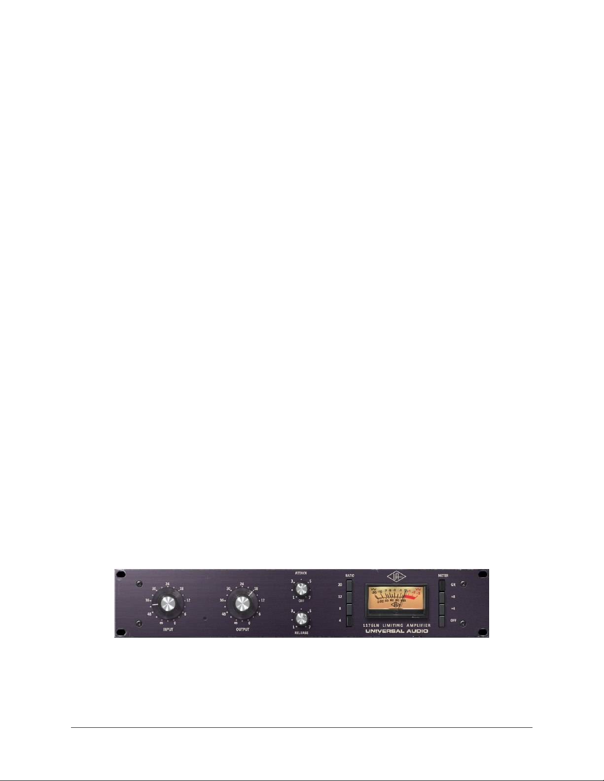
UAD Powered Plug-Ins
UAD Powered Plug‑Ins are software plug‑in titles containing DSP algorithms. UAD plug‑
ins are loaded and controlled within the Live Rack software for signal processing on
the four SHARC DSPs in the UAD‑2 Live Rack hardware. Each UAD plug‑in contains a
graphical user interface (GUI) and various control parameters that can be manipulated to
achieve the desired sonic results.
Typical UAD plug-in interface
UAD Powered Plug‑Ins are developed by Universal Audio and also by Direct Developer
(3rd‑party) partners. A wide range of titles are available that are suitable for nearly every
application. The UAD Powered Plug‑In titles that are included with UAD‑2 Live Rack
depend on the bundle included with the retail product package:
UAD‑2 Live Rack Manual Chapter 1: Introduction 15
Page 16
Core Live – The Core Live bundle includes 15 UAD plug‑in titles that were selected as a
fundamental base set for live sound applications.
Ultimate Live 2 – The Ultimate Live 2 bundle includes 84 UA‑developed titles. Note that
Direct Developer titles are not included.
UAD plug‑ins that are not included in the retail bundles are optional and purchased
separately. Optional UAD plug‑ins can be individually evaluated without functional
limitations for 14 days in demo mode, and can be purchased anytime at the UA store at
www.uaudio.com.
For complete details about how UAD Powered Plug‑Ins are used within UAD‑2 Live Rack,
see “Chapter 6: Using UAD Plug‑Ins” beginning on page 133. For complete details
about individual UAD Powered Plug‑Ins, see the UAD Plug‑Ins Manual which is placed
on the startup disk during software installation.
Note: UAD-2 Live Rack, like other UAD devices, can only use UAD Powered PlugIns which are developed specifically for the UAD DSP accelerator platform. Plugins developed for other hosts and platforms (VST, RTAS, AAX, Audio Units, native,
etc) cannot be used with the UAD-2 Live Rack system.
UAD Meter & Control Panel Software Application
The UAD Meter & Control Panel is used to authorize licensed UAD plug‑ins and configure
global functionality that pertains to all UAD devices in the same system (the application
is used for all UAD products).
The application consists of two components: The UAD Meter and the UAD Control
Panels. Complete documentation for the UAD Meter & Control Panel application is in
“Chapter 5: UAD Meter & Control Panel” beginning on page 120.
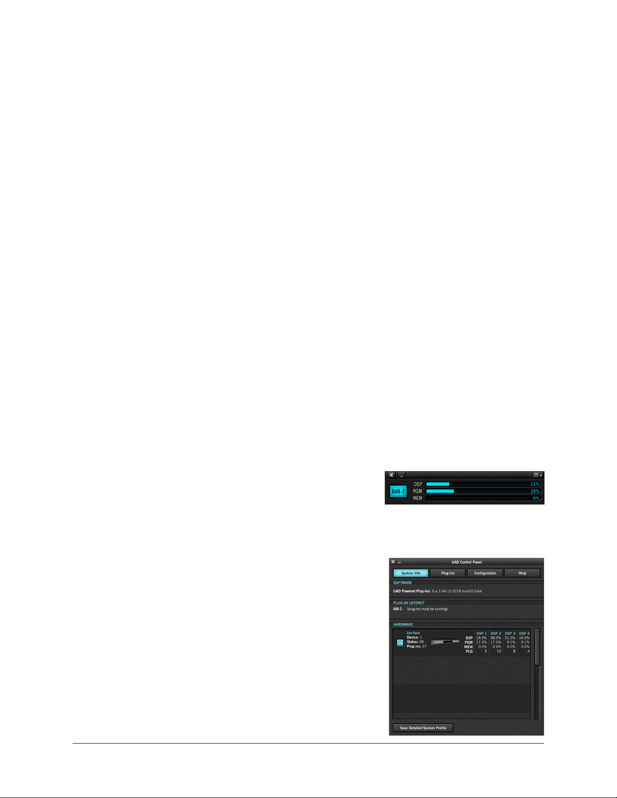
UAD Meter
The UAD Meter window (shown at right) displays the
current DSP and memory status of all active UAD‑2 Live
Rack hardware (including multiple devices).
Note: These meters are also represented within the UAD-2 Live Rack application.
UAD Control Panels
The UAD Control Panel window has multiple panels that
display, and enable control of, various UAD system, plug‑
in, and global configuration parameters.
The screenshot at right shows the System Info panel, one
of four control panel windows in the UAD Meter & Control
Panel application.
UAD‑2 Live Rack Manual Chapter 1: Introduction 16
Page 17

UA Store
The UA store at www.uaudio.com is where optional UAD plug‑in licenses can be
purchased. Promotional coupons are also redeemed here. All UAD device registrations
and plug‑in authorizations are managed here as well.
For complete details, see “Chapter 7: UA Account & Store” beginning on page 140.
Soundcraft Vi Series Consoles
Note: UAD-2 Live Rack can be used with any compatible MADI system.
Soundcraft Vi Series consoles are digital mixing/processing systems designed for use in a
live sound environment.
UAD‑2 Live Rack includes Vi console integration. Vi consoles integrate with UAD‑2 Live
Rack via two simultaneous control protocols:
MADI – Digital audio streams are routed between Vi consoles and the UAD‑2 Live Rack
hardware unit for signal processing via MADI optical I/O (note that all UAD plug‑in
signals are processed in the UAD‑2 Live Rack hardware unit, not in the Vi console). Use
the Vi Console’s powerful Insert and patching system to route signals to and from the Vi
console via MADI.
Ethernet – Digital control signals, for saving and loading UAD‑2 Live Rack configuration
Snapshots (Vi CUEs), are routed between Vi consoles and the Mac computer running
UAD‑2 Live Rack software via Ethernet.
Soundcraft Realtime Rack
Soundcraft Realtime Rack was designed
and manufactured by Universal Audio, but
sold and distributed through Soundcraft by
Harman.
Realtime Rack is functionally similar to UAD‑2 Live Rack. The main difference between
the two is that Realtime Rack has Thunderbolt 2 ports (some earliest units have
Thunderbolt 1 ports), while UAD‑2 Live Rack has Thunderbolt 3 ports. UAD‑2 Live
Rack software can be used with Realtime Rack, and Realtime Rack can be combined
with UAD‑2 Live Rack in multi‑unit systems with appropriate Thunderbolt adapters and
cabling.
Realtime Rack Support
For Realtime Rack hardware and repair support, visit www.soundcraft.com. For Realtime
Rack software support, see “Technical Support” on page 154.
UAD‑2 Live Rack Manual Chapter 1: Introduction 17
Page 18

Documentation Overview
UAD‑2 Live Rack instructions are separated by areas of functionality, as detailed below.
Documentation is copied to the computer during software installation (documentation
can also be downloaded here).
All manuals are available in PDF format only. PDF files require a free PDF reader
application such as Preview (included with macOS) or Adobe Reader.
After software installation, all UAD‑2 Live Rack documentation can be found on the
computer at the following location:
• /Applications/Universal Audio/
Tip: Documentation can also be accessed by clicking the “View Documentation”
button in the Help panel within the UAD Meter & Control Panel application.
UAD-2 Live Rack Manual
The UAD‑2 Live Rack Manual (this document) contains complete information about the
hardware unit and how to configure and operate the UAD‑2 Live Rack software. Included
are detailed descriptions for all connections, features, and control functions.
This manual also contains details about the UAD Meter & Control Panel application,
obtaining optional UAD plug‑in licenses at the UA online store, and more.
UAD Plug-Ins Manual
The features and functionality of all individual UAD Powered Plug‑Ins is detailed in the
UAD Plug‑Ins Manual. Refer to that document to learn about the operation, controls, and
user interface of each plug‑in that is developed by Universal Audio.
Direct Developer Plug-Ins
UAD Powered Plug‑Ins includes plug‑ins from Direct Developer partners. Documentation
for these 3rd‑party plug‑ins are separate files that are written and provided by the plug‑in
developers themselves. The filenames for these plug‑ins are the same as the plug‑in title
names.
Soundcraft Vi Series Consoles
Operating instructions for Vi Series consoles is beyond the scope of UAD‑2 Live Rack
documentation. Refer to Soundcraft documentation for all Vi system operating details.
Hyperlinks
Hyperlinks to other pages in the same file and web pages are highlighted in blue text.
Click a hyperlink to jump directly to the linked item.
Tip: Use the “back” button in the PDF reader application to return to the previous
page after clicking a hyperlink.
Technical Support
To contact Universal Audio for help, see “Technical Support” on page 154.
UAD‑2 Live Rack Manual Chapter 1: Introduction 18
Page 19
Chapter 2: Hardware
UNIVERSAL AUDIO, INC.
1394b 1 1394b 2
MADI IN
IN
ON
OFF
PSU 2
100V-240V
0.30A 50-60 Hz
DESIGNED IN CALIFORNIA • MADE IN CHINA
UNIVERSAL AUDIO
UAD-2 LIVE RACK
R-RMM-UAO-UAD-2 LIVE RACK
WORD
CLOCK
WORD
CLOCK
RESET
1394b 1 1394b 2
MADI IN
IN
ON
OFF
DESIGNED IN CALIFORNIA • MADE IN CHINA
UNIVERSAL AUDIO
UAD-2 LIVE RACK
PSU 2
100V-240V
0.30A 50-60 Hz
R-RMM-UAO-UAD-2 LIVE RACK
UNIVERSAL AUDIO, INC.
RESET
Hardware Overview
The UAD‑2 Live Rack hardware is the 1U rack device that performs audio signal
processing on digital audio streams via MADI optical I/O. The hardware unit contains four
SHARC DSPs that process the UAD Powered Plug‑In algorithms. Each unit can process
up to 16 MADI streams, and up to four units can be combined to process a total of 64
MADI streams. Additionally, each unit has dual‑redundant internal power supplies and
automatic failover protection.
Each UAD‑2 Live Rack hardware unit is configured and controlled by the UAD‑2 Live
Rack software application. The MADI channels being processed by each hardware unit is
specified in the Settings tab in the UAD‑2 Live Rack software.
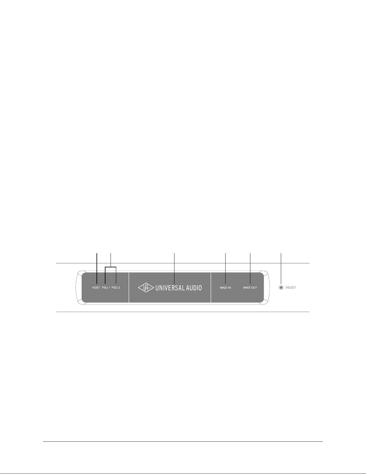
Front Panel
This section describes the function of all visual indicators and controls on the UAD‑2
Live Rack front panel. There are five visual‑only elements and one recessed hardware
RESET button.
1 2 3 4 5 6
(1) HOST Indicator
The HOST indicator displays the status of the rear panel Thunderbolt connection to
the host computer system. The indicator is lit when UAD‑2 Live Rack is connected to,
and properly communicating with, the Mac computer that is running UAD‑2 Live Rack
software.
The UAD‑2 Live Rack software must be properly installed and configured on the host
computer to enable driver connectivity, and the HOST indicator must be illuminated to
use UAD‑2 Live Rack with all computer and Vi console operations.
UAD‑2 Live Rack Manual Chapter 2: Hardware 19
Page 20

(2) PSU Indicators
These indicators display the status of the rear panel dual redundant internal power
supply units (PSU). There is one indicator for each power supply unit (PSU 1 and PSU
2). The color of each indicator displays the status of the PSU as follows:
White – The PSU is operating normally. The PSU is connected to AC power, and the
power switch for the PSU (rear panel) is in the ON position.
Red – The PSU is not delivering power. This state is caused by one or more of the
following conditions:
• The PSU is not connected to AC power
• The power switch for the PSU is in the OFF position
• The PSU has malfunctioned
PSU Indicator notes:
• If one internal power supply unit fails, UAD‑2 Live Rack will continue to process
audio signals.
• It is normal for the PSU indicator to flash red upon power up of the hardware
(3) POWER Indicator
The Universal Audio text and logo are lit when the hardware unit is receiving proper
operating voltages from one or both internal power supply units.
(4 & 5) MADI Indicators
These indicators represent whether or not MADI digital audio signals are present at the
rear panel MADI I/O connectors. There is one indicator for MADI input and one for MADI
output. The state of each indicator represents the MADI signals as follows:
White (bright) – The audio level of any channel in the MADI stream is above ‑60 dB.
White (dim) – The MADI stream is detected but no channels are above ‑60 dB.
Black (off) – No audio signals are present in the MADI stream.
(4) MADI IN Indicator
Indicates the state of digital audio signals at the rear panel MADI input connector.
(5) MADI OUT Indicator
Indicates the state of digital audio signals at the rear panel MADI output connector.
(6) RESET Button
This recessed button executes a hardware reset and initializes the unit. Reset should
only be performed if there is an unrecoverable failure and all other troubleshooting
techniques are exhausted.
Note: Pressing this switch interrupts power to the UAD-2 Live Rack hardware unit.
It performs the same function as manually turning off the unit with the rear panel
PSU switches.
UAD‑2 Live Rack Manual Chapter 2: Hardware 20
Page 21
DESIGNED IN CALIFORNIA • MADE IN CHINA
UAD-2 Live Rack
DESIGNED IN CALIFORNIA • MADE IN CHINA
UNIVERSAL AUDIO
UAD-2 LIVE RACK
PSU 1
100V-240V
0.30A 50-60 Hz
PSU 2
100V-240V
0.30A 50-60 Hz
R-RMM-UAO-UAD-2 LIVE RACK
UAD-2 Live Rack
DESIGNED IN CALIFORNIA • MADE IN CHINA
UNIVERSAL AUDIO
UAD-2 LIVE RACK
PSU 1
100V-240V
0.30A 50-60 Hz
PSU 2
100V-240V
0.30A 50-60 Hz
R-RMM-UAO-UAD-2 LIVE RACK
1 2 3 4 5 6
Rear Panel
This section describes the function of all switches and connectors on the UAD‑2 Live
Rack front panel.
1
2
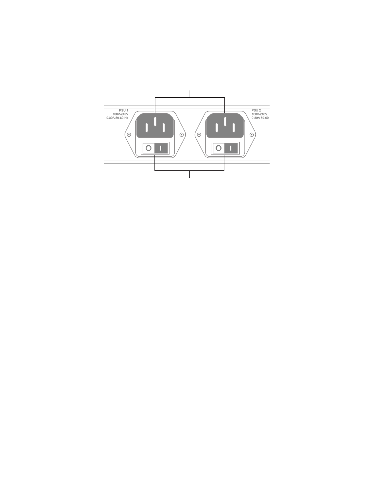
(1) AC Power Inputs
Connect standard detachable IEC power cables to the dual redundant internal power
supply units here.
Each PSU accepts 100VAC – 240VAC, 50‑60 Hz. The UAD‑2 Live Rack hardware unit
draws a total maximum of 30 Watts of power.
Note: One PSU and power cable can be used if failover operation is not desired.
(2) Power Switches
Each power supply unit has its own integrated power switch. AC power is passed to the
PSU when the toggle switch is in the in (“I”) position.
Automatic Failover
UAD‑2 Live Rack’s integrated failover circuitry automatically maintains power to
the UAD‑2 Live Rack hardware. In the event that one of the internal power supplies
malfunctions or if power to one of the PSUs is interrupted, UAD‑2 Live Rack will
continue to process audio.
UAD‑2 Live Rack Manual Chapter 2: Hardware 21
Page 22
Rear Panel (continued)
1394b 1 1394b 2
MADI IN
WORD
CLOCK
WORD
CLOCK
RESET
1394b 1 1394b 2
MADI IN
IN
ON
OFF
UNIVERSAL AUDIO, INC.
RESET
1394b 1 1394b 2
MADI IN
IN
ON
OFF
UNIVERSAL AUDIO, INC.
3 4 5 6
7 8 9
.
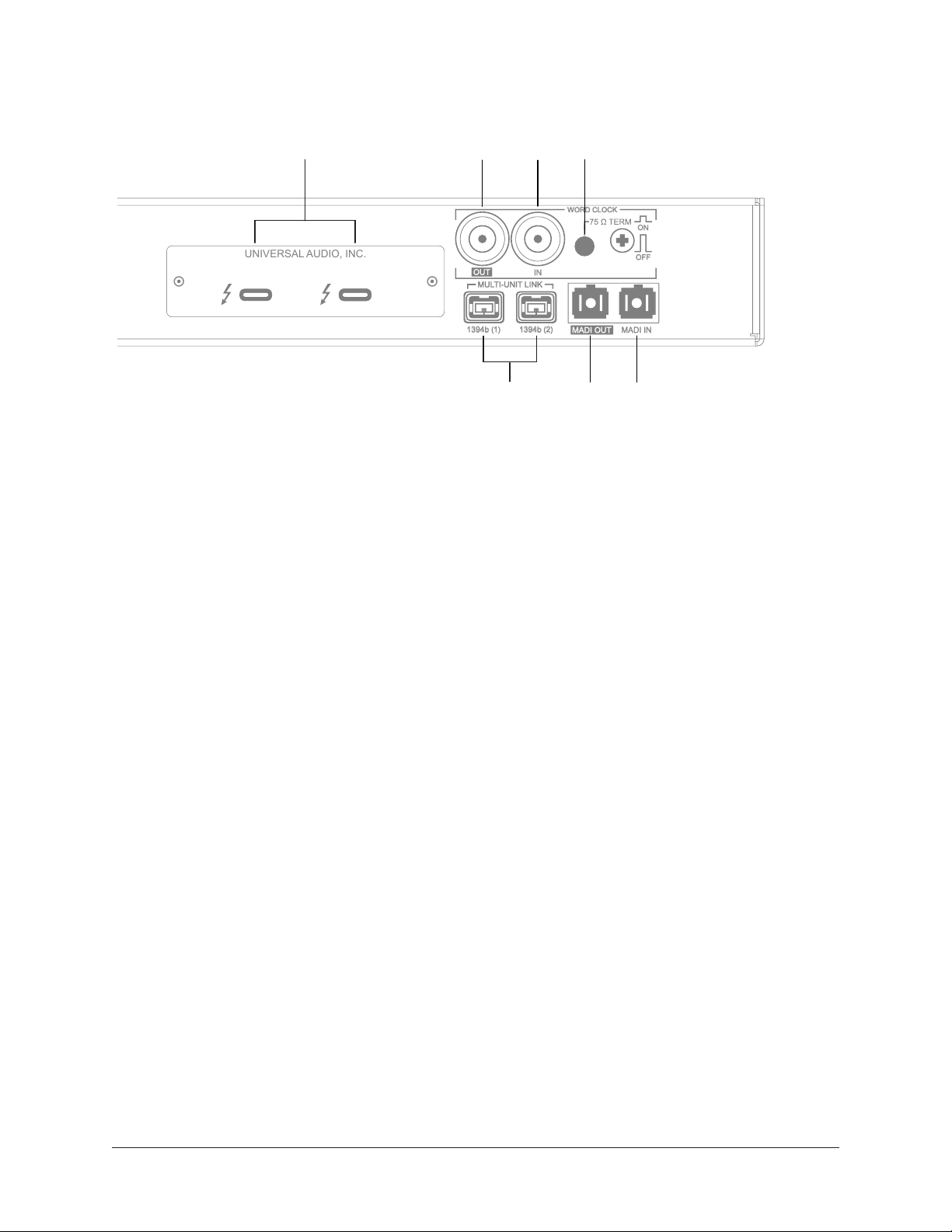
(3) Thunderbolt 3 Ports
Connect a Thunderbolt cable (not included) between one of these ports and the
Thunderbolt 3 port on the Mac host computer that is running the UAD‑2 Live Rack
software application. The HOST indicator on the front panel is lit when the connection is
established.
Either port can be used for the host computer connection. The other port remains
available for Thunderbolt 3 daisy‑chain connections, for example additional UAD‑2 Live
Rack units or the Apple Thunderbolt 3 to Gigabit Ethernet Adapter.
Note: Although Thunderbolt 3 always uses USB-C connectors, not all USB-C
computer ports are Thunderbolt 3 ports.
(4) Word Clock Out
This BNC connector transmits a standard (1x) word clock when UAD‑2 Live Rack is set
to use its internal clock. The clock rate sent by this port matches the current system
sample rate, as specified in the Hardware tab within the UAD‑2 Live Rack software
application.
When UAD‑2 Live Rack is set to use external word clock as its clock, UAD‑2 Live Rack
is a word clock slave. If the incoming external word clock is within ±0.5% of a supported
sample rate (44.1 kHz, 48 kHz, 88.2 kHz, 96 kHz), Word Clock Out will mirror Word
Clock In with a slight phase delay of about 40 nanoseconds.
UAD‑2 Live Rack Manual Chapter 2: Hardware 22
Page 23

(5) Word Clock In
UAD‑2 Live Rack’s internal clock can be synchronized (slaved) to an external master
word clock. This is accomplished by setting UAD‑2 Live Rack’s clock source to Word
Clock in the Hardware tab within the UAD‑2 Live Rack software’s Settings view,
connecting the external word clock’s BNC connector to UAD‑2 Live Rack’s word clock
input, and setting the external device to transmit word clock. If UAD‑2 Live Rack is the
last device in the clock chain, the Termination switch (6) should be engaged.
Note: UAD-2 Live Rack can be synchronized to an external “1x” clock signal only.
Superclock, overclocking, and subclocking are not supported.
(6) Word Clock Termination Switch
This pushbutton switch provides internal 75‑ohm word clock input signal termination
when required. Word clock termination is active when the switch is engaged (depressed).
UAD‑2 Live Rack’s termination switch should only be engaged when UAD‑2 Live Rack
is set to sync to external word clock and it is the last device at the receiving end of a
word clock cable. For example, if UAD‑2 Live Rack is the last “slave” unit at the end
of a clock chain (when UAD‑2 Live Rack’s word clock out port is not used), termination
should be active.
(7) 1394b Ports (no function)
The 1394b ports are for manufacturing purposes only. They have no functionality within
the UAD‑2 Live Rack system.
Important: Do not attach any devices, including a computer, to the 1394b ports.
(8 & 9) MADI I/O Ports
The MADI I/O ports are used for the digital audio interconnections between the UAD‑2
Live Rack hardware unit and other MADI equipment. Dual Optical SC‑Plug (ISO/IEC
9314‑3) connectors are provided.
(8) MADI OUT
Connect this port to the MADI optical input on the MADI device.
(9) MADI IN
Connect this port to the MADI optical output on the MADI device.
UAD‑2 Live Rack Manual Chapter 2: Hardware 23
Page 24

Standalone Behavior
UAD‑2 Live Rack supports limited standalone functionality in the event that the
Thunderbolt 3 connection to the host computer is lost, or if the UAD‑2 Live Rack
hardware unit is power cycled and no host computer is found upon re‑powering the
hardware.
Thunderbolt 3 connection lost – In the event that the Thunderbolt 3 cable is removed at
one or both ends, or if the host computer is otherwise no longer detected, UAD‑2 Live
Rack will continue to process audio in the same state as when the connection was lost,
including UAD plug‑in processing. If/when the host connection is reestablished, the
UAD‑2 Live Rack software will be updated to reflect the current state of the hardware,
and software control is resumed.
Important: Reestablishing the Thunderbolt 3 host-to-hardware connection will
cause a temporary mute of the audio streams as channels and plug-ins are reallocated. In the event of a mid-show failure, wait until it is acceptable to hear a
mute in the audio path (e.g., not in the middle of a song).
Power cycled, no host found – In the event that power to the UAD‑2 Live Rack hardware
unit is completely interrupted then reestablished and/or the unit is manually power
cycled or reset, and the host computer cannot be detected after re‑powering the
hardware, UAD‑2 Live Rack will function in “all MADI inputs to all MADI outputs” mode
without UAD plug‑in processing. This ensures that audio can still be routed by the Vi
console, even if the UAD‑2 Live Rack software connection cannot be established.
UAD‑2 Live Rack Manual Chapter 2: Hardware 24
Page 25

Chapter 3: System Setup
Overview
UAD‑2 Live Rack system setup requires these primary procedures, all of which are
detailed in this chapter:
• System connections (device wiring)
• UAD‑2 Live Rack software installation
• Hardware device registration and UAD plug‑in authorization
• Computer operating system software configuration
• UAD‑2 Live Rack software configuration
System Requirements
Note: Cables and adapters are not included.
• UAD‑2 Live Rack hardware unit
• Apple Mac computer with available Thunderbolt 3 port*
• MacOS 10.13.3 High Sierra
• Internet connection to download software and authorize UAD plug‑ins
• 6 gigabytes available storage
• Thunderbolt 3 cable for each UAD‑2 Live Rack unit
• (2) single MADI Optical SC cables or (1) Duplex MADI optical SC cable
for each UAD‑2 Live Rack unit (multi‑unit setups cannot use duplex MADI cables)
*Macs with Thunderbolt 1 or Thunderbolt 2 ports can be used with appropriate
adapters and cables. For details, see "Thunderbolt 1 and 2 Mac Wiring" on page
28.
If using Soundcraft Vi-Series Console
• Category 5 Ethernet cable
• Belkin USB‑C to Gigabit Ethernet Adapter
• Apple store part number HJKF2ZM/A or MD463LL/A
• Belkin store part number F2CU040dsWHTAPL
UAD‑2 Live Rack Manual Chapter 3: System Setup 25
Page 26
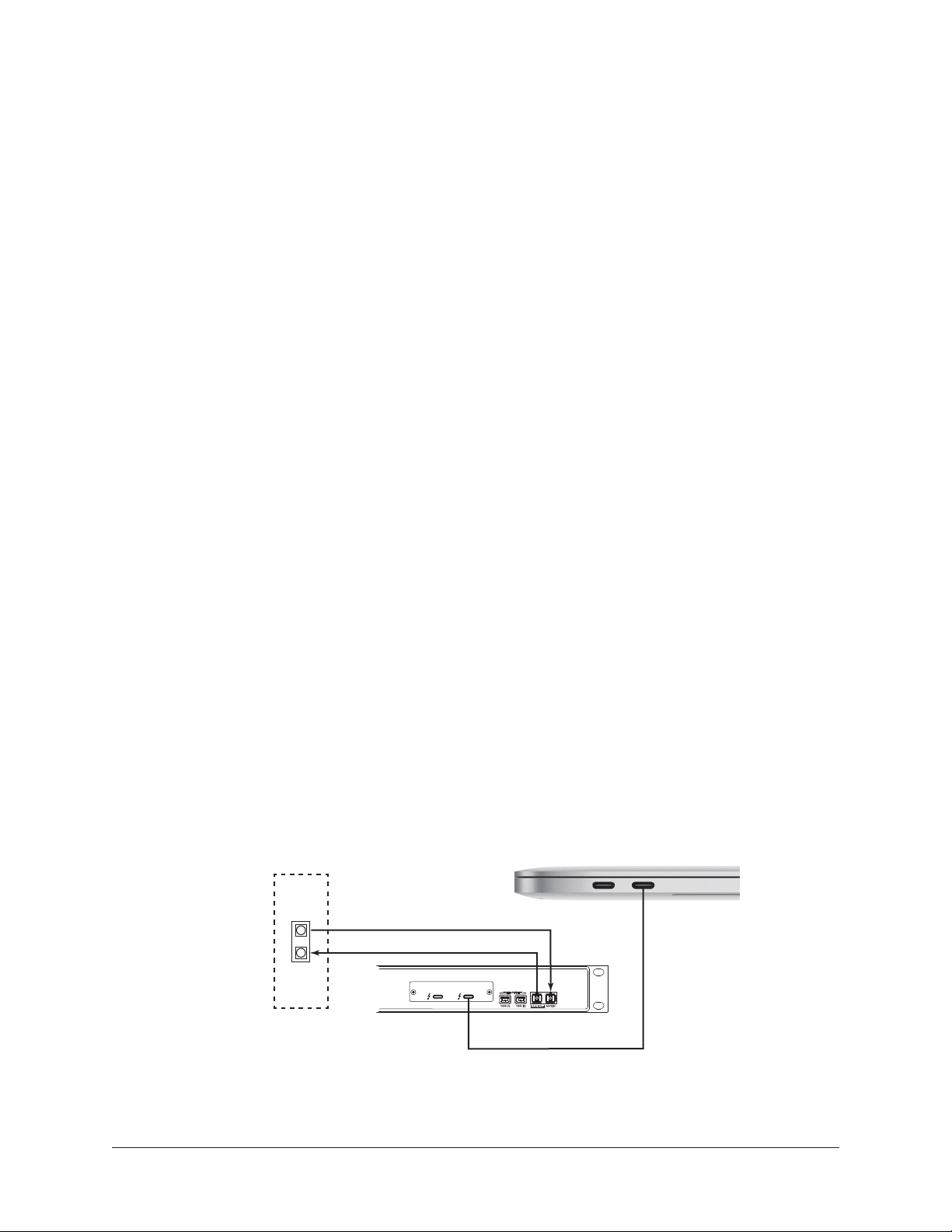
System Connections
Interconnect the UAD‑2 Live Rack hardware unit, the Live Rack software host computer,
and the MADI device following the illustrations in this section.
About UAD-2 Live Rack system connections
• Do not connect any devices, including a computer, to the UAD‑2 Live Rack 1394b
ports. These ports are for manufacturing purposes only.
• The MADI channels to be processed by UAD‑2 Live Rack are specified in the
Hardware panel of the Settings page within the Live Rack software application.
• When synchronizing to external Word Clock, the first UAD‑2 Live Rack unit (MADI
channels 1 – 16) must receive the Word Clock, then pass the clock to the second
unit and so on (via daisy‑chaining), for up to four units.
• Duplex MADI cables cannot be used with multi‑unit configurations.
• All Live Rack MIDI control commands are received via the Audio MIDI Setup
application in macOS. Refer to the MIDI control device documentation for setup.
• When operating the UAD‑2 Live Rack hardware, the unit must be placed or
mounted with the vent holes facing up.
Single Unit Wiring
The diagram below illustrates connections for one UAD‑2 Live Rack unit for up to 16
MADI channels of UAD plug‑in processing.
Cables Required (not included):
• One Thunderbolt 3 cable between UAD‑2 Live Rack and the host computer for
software control
• Two MADI optical cables (or a single duplex cable) between UAD‑2 Live Rack and
the MADI device for digital audio send/return
MADI Device
MADI Optical SC
IN–MADI–OUT
UNIVERSAL AUDIO, INC.
1394b 1 1394b 2
UAD-2 Live Rack Unit
Thunderbolt 3 Mac
MADI IN
System connections for single unit setup
UAD‑2 Live Rack Manual Chapter 3: System Setup 26
Thunderbolt 3
Page 27

Multi-Unit Wiring
UNIVERSAL AUDIO, INC.
1394b 1 1394b 2
MADI IN
MADI Device
MADI Optical SC
Thunderbolt 3
UAD-2 Live Rack Unit
Thunderbolt 3 Mac
IN–MADI–OUT
The diagram below illustrates connections for 2, 3, or 4 UAD‑2 Live Rack units for up to
64 MADI channels of UAD plug‑in processing (16 MADI channels for each UAD‑2 Live
Rack unit).
Cables Required (not included):
• One Thunderbolt 3 cable between UAD‑2 Live Rack and the computer for software
control
• One Thunderbolt 3 cable for each additional UAD‑2 Live Rack for unit interlinks
• One MADI optical cable between the MADI device and the first UAD‑2 Live Rack
for digital audio send
• One MADI optical cable between the last UAD‑2 Live Rack and Vi console for
digital audio return
• One MADI optical cable for each additional UAD‑2 Live Rack for unit interlinki
MADI Optical SC
UNIVERSAL AUDIO, INC.
1394b 1 1394b 2
MADI IN
MADI Device
UNIVERSAL AUDIO, INC.
1394b 1 1394b 2
MADI IN
UAD-2 Live Rack Units
IN–MADI–OUT
UNIVERSAL AUDIO, INC.
1394b 1 1394b 2
UNIVERSAL AUDIO, INC.
System connections for multi-unit setup
1394b 1 1394b 2
MADI IN
MADI IN
Thunderbolt 3
Thunderbolt 3 Mac
UAD‑2 Live Rack Manual Chapter 3: System Setup 27
Page 28
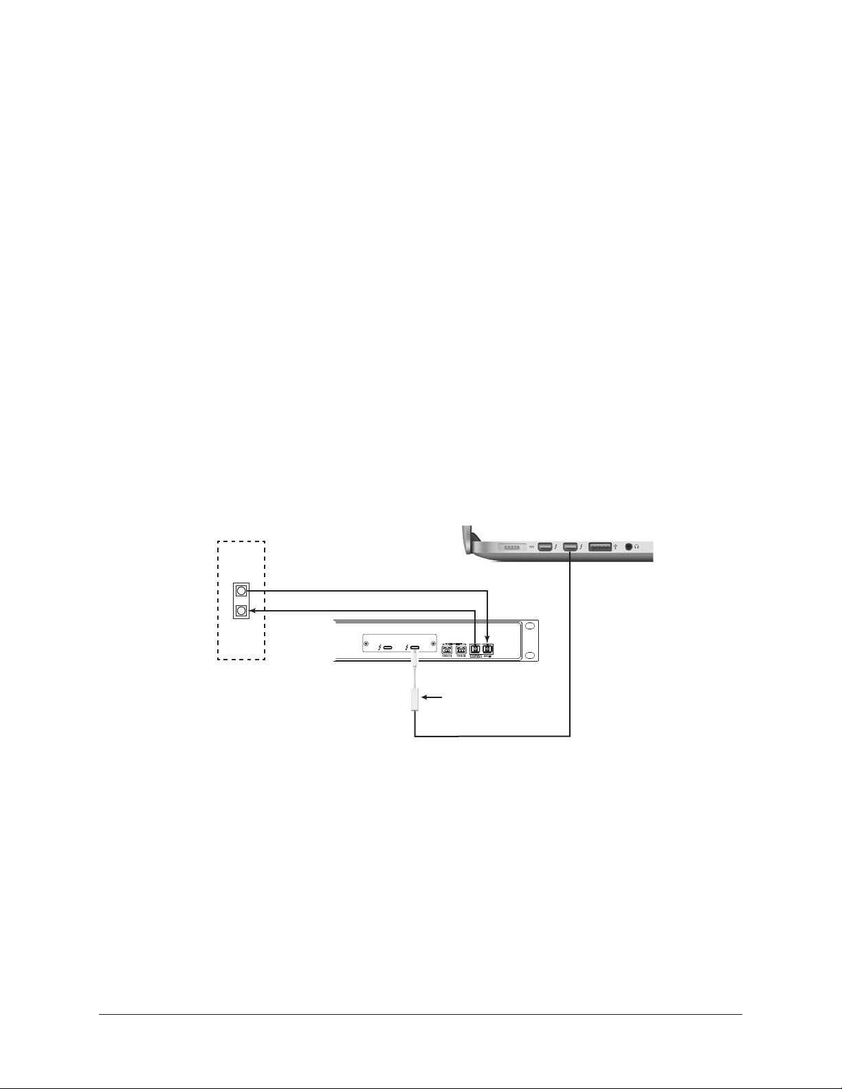
Thunderbolt 1 and 2 Mac Wiring
UNIVERSAL AUDIO, INC.
1394b 1 1394b 2
MADI IN
UNIVERSAL AUDIO, INC.
1394b 1 1394b 2
MADI IN
UNIVERSAL AUDIO, INC.
1394b 1 1394b 2
MADI IN
UNIVERSAL AUDIO, INC.
1394b 1 1394b 2
MADI IN
UNIVERSAL AUDIO, INC.
1394b 1 1394b 2
MADI IN
MADI Device
MADI Optical SC
Thunderbolt 3
UAD-2 Live Rack Unit
UAD-2 Live Rack Units
Thunderbolt 3 Mac
Thunderbolt 3 Mac
MADI Optical SC
Thunderbolt 3
IN–MADI–OUT
IN–MADI–OUT
UAD‑2 Live Rack is designed for a direct connection to a Thunderbolt 3 Mac. However,
older Macs with Thunderbolt 1 or Thunderbolt 2 ports can be used via a Thunderbolt 2
cable and the Apple Thunderbolt 3 to Thunderbolt 2 adapter.
Additional Items Needed with Thunderbolt 1 and Thunderbolt 2 Macs
• (1) Apple Thunderbolt 3 to Thunderbolt 2 Adapter (Apple part number
MMEL2AM/A) at the UAD‑2 Live Rack port for the Thunderbolt 2 cable
connection.
• (1) Thunderbolt 2 cable for the Mac computer connection. Note that this cable
replaces the Thunderbolt 3 cable that would be used for a Thunderbolt 3 port at
the computer.
Thunderbolt 1 and 2 Mac Connection Notes
• The wiring for Thunderbolt 1 and Thunderbolt 2 Macs is identical.
• A multi‑unit system with a Thunderbolt 1 or 2 Mac is similar to Thunderbolt 3
wiring. The only difference is with the host computer connection. The Thunderbolt
2 host computer connection in the diagram below is the same for single and
multi‑unit setups.
MADI Device
IN–MADI–OUT
MADI Optical SC
UNIVERSAL AUDIO, INC.
UAD-2 Live Rack Unit
1394b 1 1394b 2
Thunderbolt 2 Mac
MADI IN
Thunderbolt 2
cable
Thunderbolt 3 to
Thunderbolt 2 Adapter
System connections for Thunderbolt 1 and Thunderbolt 2 Macs
UAD‑2 Live Rack Manual Chapter 3: System Setup 28
Page 29
UNIVERSAL AUDIO, INC.
1394b 1 1394b 2
MADI IN
UNIVERSAL AUDIO, INC.
1394b 1 1394b 2
MADI IN
UNIVERSAL AUDIO, INC.
1394b 1 1394b 2
MADI IN
UNIVERSAL AUDIO, INC.
1394b 1 1394b 2
MADI IN
UNIVERSAL AUDIO, INC.
1394b 1 1394b 2
MADI IN
MADI Optical SC
Cat 5 Ethernet
Thunderbolt 3
Vi Surface
Rear Panel
UAD-2 Live Rack Unit
UAD-2 Live Rack Units
Thunderbolt 3 Mac
USB-C
Ethernet
Adapter
Vi MADI Ports
MADI Optical SC
Cat 5 Ethernet
Thunderbolt 3
HiQnet™
Ethernet
Port
HiQnet™
Ethernet
Port
UNIVERSAL AUDIO, INC.
1394b 1 1394b 2
MADI IN
Soundcraft Vi
MADI Ports
MADI Optical SC
Cat 5 Ethernet cable
Thunderbolt 2
cable
Soundcraft Vi
Console Surface
Rear Panel
UAD-2 Live Rack Unit
Thunderbolt 2 Mac
USB-C
Ethernet
Adapter
Thunderbolt 3 to
Thunderbolt 2 Adapter
HiQnet™
Ethernet
Port
SoundCraft Vi-Series Console Connections
Connections to SoundCraft Vi‑series consoles are the same as other MADI devices, as
shown on previous pages, with the addition of HiQnet™ (Ethernet) wiring for integrated
Snapshot control.
Vi-Series Console Connection Notes
• The HiQnet port on early Vi1 consoles (serial numbers lower than 30210956) is
only able to drive short cable lengths, with a maximum recommended length 1
meter (3 feet). Therefore, use a network switch positioned close to the rear of the
console to extend the cable length if required with these early Vi1 consoles.
• The HiQnet port on other Vi consoles is capable of driving standard Ethernet
distances of up to 100 meters.
• The HiQnet port uses the same 8P8C modular connector as the Dante™ ports
available on Vi consoles. Connect to the HiQnet port only.
Connect UAD-2 Live Rack to the HiQnet port
• Macs with Thunderbolt 1 or Thunderbolt 2 ports can be used with additional
adapters. For details, see "Thunderbolt 1 and 2 Mac Wiring" on page 28.
• Interconnect the UAD‑2 Live Rack hardware unit, the Live Rack software host
computer, and the SoundCraft Vi‑series console following the illustrations on the
following pages.
UAD‑2 Live Rack Manual Chapter 3: System Setup 29
Page 30
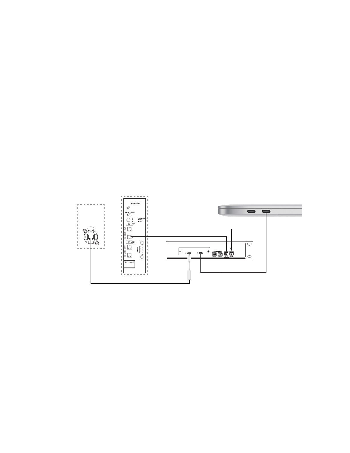
1394b 1 1394b 2
MADI IN
UNIVERSAL AUDIO, INC.
1394b 1 1394b 2
MADI IN
UNIVERSAL AUDIO, INC.
1394b 1 1394b 2
MADI IN
UNIVERSAL AUDIO, INC.
1394b 1 1394b 2
MADI IN
UNIVERSAL AUDIO, INC.
1394b 1 1394b 2
MADI IN
Thunderbolt 3
UAD-2 Live Rack Unit
UAD-2 Live Rack Unit
UAD-2 Live Rack Units
Thunderbolt 3 Mac
MADI Device
MADI Optical SC
Thunderbolt 3
IN–MADI–OUT
IN–MADI–OUT
UNIVERSAL AUDIO, INC.
1394b 1 1394b 2
MADI IN
MADI Device
MADI Optical SC
Thunderbolt 2
cable
Thunderbolt 2 Mac
Thunderbolt 3 to
Thunderbolt 2 Adapter
Single Unit Wiring with SoundCraft Vi Consoles
The diagram below illustrates connections for one UAD‑2 Live Rack unit for up to 16
MADI channels of UAD plug‑in processing.
Cables Required (not included):
• One Thunderbolt 3 cable between UAD‑2 Live Rack and the computer for software
control
• Two MADI optical cables (or a single duplex cable) between UAD‑2 Live Rack and
the Vi console for digital audio send/return
• One Cat 5 Ethernet cable between host Mac and Vi console for snapshot control
• One Belkin USB‑C to Gigabit Ethernet Adapter for Vi console Ethernet
• Apple store part number HJKF2ZM/A or MD463LL/A
• Belkin store part number F2CU040dsWHTAPL
Soundcraft Vi
Console Surface
Rear Panel
HiQnet™
Ethernet
Port
Soundcraft Vi
MADI Ports
MADI Optical SC
Thunderbolt 3 Mac
Cat 5 Ethernet
USB-C
Ethernet
Adapter
UNIVERSAL AUDIO, INC.
1394b 1 1394b 2
UAD-2 Live Rack Unit
MADI IN
Thunderbolt 3
System connections for single unit setup with SoundCraft Vi console
UAD‑2 Live Rack Manual Chapter 3: System Setup 30
Page 31
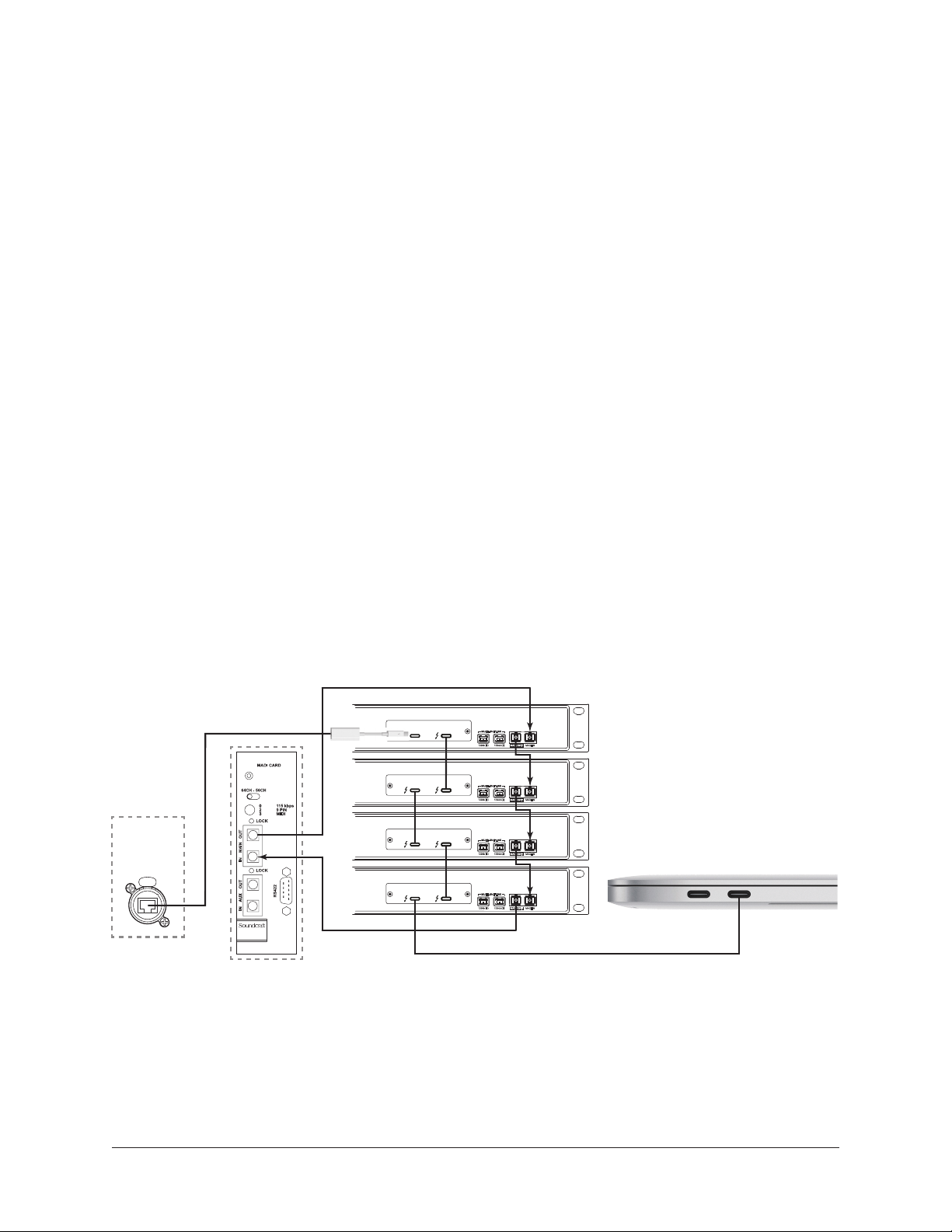
1394b 1 1394b 2
MADI IN
UNIVERSAL AUDIO, INC.
1394b 1 1394b 2
MADI IN
UNIVERSAL AUDIO, INC.
1394b 1 1394b 2
MADI IN
UAD-2 Live Rack Unit
Thunderbolt 3 Mac
Thunderbolt 3
Soundcraft Vi
MADI Ports
MADI Optical SC
Cat 5 Ethernet
Thunderbolt 3
Soundcraft Vi
Console Surface
Rear Panel
Rear Panel
UAD-2 Live Rack Unit
Thunderbolt 3 Mac
USB-C
Ethernet
Adapter
Vi MADI Ports
HiQnet™
Ethernet
Port
IN–MADI–OUT
IN–MADI–OUT
UNIVERSAL AUDIO, INC.
1394b 1 1394b 2
MADI IN
MADI Device
MADI Optical SC
Thunderbolt 2
cable
Thunderbolt 2 Mac
Thunderbolt 3 to
Thunderbolt 2 Adapter
Multi-Unit Wiring with SoundCraft Vi Consoles
The diagram below illustrates connections for 2, 3, or 4 UAD‑2 Live Rack units for up to
64 MADI channels of UAD plug‑in processing (16 MADI channels for each UAD‑2 Live
Rack unit).
Cables Required (not included):
• One Thunderbolt 3 cable between UAD‑2 Live Rack and the computer for software
control
• One Thunderbolt 3 cable for each additional UAD‑2 Live Rack for unit interlinks
• One MADI optical cable between the MADI device and the first UAD‑2 Live Rack
for digital audio send
• One MADI optical cable between the last UAD‑2 Live Rack and Vi console for
digital audio return
• One MADI optical cable for each additional UAD‑2 Live Rack for unit interlink
Note: Duplex cables cannot be used with multi-unit configurations.
• One Cat 5 Ethernet cable between host Mac and Vi console for snapshot control
• One Belkin USB‑C to Gigabit Ethernet Adapter for Vi console Ethernet
• Apple store part number HJKF2ZM/A or MD463LL/A
• Belkin store part number F2CU040dsWHTAPL
HiQnet™
Ethernet
Port
Cat 5 Ethernet
MADI Optical SC
UNIVERSAL AUDIO, INC.
UNIVERSAL AUDIO, INC.
UNIVERSAL AUDIO, INC.
UNIVERSAL AUDIO, INC.
1394b 1 1394b 2
1394b 1 1394b 2
MADI IN
MADI IN
UAD-2 Live Rack Units
1394b 1 1394b 2
1394b 1 1394b 2
MADI IN
MADI IN
Thunderbolt 3 Mac
Vi Surface
Thunderbolt 3
System connections for multi-unit setup with Soundcraft Vi console
UAD‑2 Live Rack Manual Chapter 3: System Setup 31
Page 32

Software Installation
Complete UAD‑2 Live Rack software installation consists of two main steps:
• UAD‑2 Live Rack software installation
• Device registration and UAD plug‑in authorization
Preparation
• Close all open files and applications before Live Rack software installation. The
installer requires a restart after installation.
• If you are updating to a newer version of Live Rack software or installing
additional UAD‑2 Live Rack hardware units, it is not necessary to remove or
disconnect the previous installations.
Software Installation Procedure
To install the UAD-2 Live Rack software and UAD plug-ins:
1. Verify the UAD‑2 Live Rack hardware unit(s) is powered and properly
connected to the host computer via Thunderbolt.
2. Download the UAD‑2 Live Rack software installer:
www.uaudio.com/downloads
3. Open the downloaded installer application. The installer will guide you.
Note: If prompted to update the firmware, see "About Firmware Updates" below.
4. Restart the computer when prompted. Software installation is complete.
5. Proceed to Device Registration & Authorization on page 33.
About Firmware Updates
• Firmware updates for the UAD‑2 Live Rack hardware may be included within the
software to enhance system functionality. The Live Rack software prompts for
firmware updates automatically (if available). For optimum results, always update
the firmware by clicking "OK" if prompted by the software.
• After "OK" is clicked and the firmware is installed, a notification appears. After
the notification, power off the UAD‑2 Live Rack hardware. The first time power is
reapplied, the hardware will take an extra 20–30 seconds to initialize, after which
the firmware update process is complete.
Important: Do not interrupt system power during the firmware update routine.
UAD‑2 Live Rack Manual Chapter 3: System Setup 32
Page 33

Device Registration & Authorization
The UAD‑2 Live Rack hardware unit must be registered and authorized at uaudio.com
to unlock UAD plug‑ins that are bundled with the product. Registration only needs to
be completed once. However, authorization must be completed each time the Live Rack
software is updated.
About Registration
UAD‑2 Live Rack hardware registration is triggered automatically as part of the initial
authorization process. The first time authorization is initiated, the web browser launches
and connects to the UA store. Follow the instructions on the web pages to create an
account, register the hardware, claim bundled UAD plug‑ins, and authorize the system.
About Authorization
The UAD‑2 Live Rack hardware stores its UAD plug‑in license authorizations in the
device itself, so the unit can be connected to a different computer without repeating
the authorization process. UAD plug‑ins that were not bundled with the product can be
evaluated without functional restriction during a Demo Mode that expires after 14 days.
Authorization Procedure
Before proceeding, confirm that the UAD‑2 Live Rack software is has already been
installed and the UAD‑2 Live Rack hardware is powered and connected to the computer
via Thunderbolt (the hardware and software systems must be communicating properly).
Important: The following procedure requires an Internet connection to the host
computer. To authorize a system that is not connected to the Internet, see the
Offline Authorization Procedure on page 34.
To authorize UAD-2 Live Rack and UAD plug-ins:
1. Launch the UAD Meter & Control Panel. To open the application, click its
icon (shown at right) in the macOS Dock.
2. Open the Plug‑Ins panel within the UAD Meter & Control Panel application.
To access the panel, click the blue UAD‑2 button in the UAD Meter window,
as shown below.
UAD‑2 Live Rack Manual Chapter 3: System Setup 33
Page 34

3. Click the “Authorize Plug‑Ins…” button in the Plug‑Ins panel. The software
connects to the Universal Audio authorization servers.
4. After a few moments, the Authorization Status window appears and
"Authorizations successfully updated" is displayed. Click OK to close the window.
5. System authorization is complete. Proceed to Operating System Software
Configuration on page 36.
Offline Authorization Procedure
If the UAD‑2 Live Rack computer is not connected to the Internet, you will need to
manually transfer the registration URL into the browser of a web‑enabled computer,
download the authorization file on the web computer, then transfer the authorization file
back to the UAD‑2 Live Rack computer.
Important: If the UAD-2 Live Rack computer is not connected to the internet,
you must manually transfer the exact registration URL into the browser of a webenabled computer.
To authorize a system that is not connected to the Internet:
1. Install the UAD‑2 Live Rack software and hardware using the procedures detailed
earlier in this chapter. The UAD‑2 Live Rack hardware must be powered on and
the system must be communicating properly.
2. Launch the UAD Meter & Control Panel application, open the Plug‑Ins Panel,
and click the "Authorize Plug‑Ins" button by following step numbers 1, 2, and
3 on page 33. The default web browser opens with the registration URL in
the address bar, along with an error that the computer is not connected to the
Internet.
(continued)
UAD‑2 Live Rack Manual Chapter 3: System Setup 34
Page 35

3. You need to enter this URL in a web‑connected computer, so either:
a. Drag the URL icon in the browser’s address bar to the Desktop to create
a weblink shortcut (recommended, as illustrated below) then transfer the
weblink shortcut to the internet computer via a storage device or network, OR
b. Carefully write down the URL, EXACTLY as it appears in the address field.
1. Click+Hold URL icon
in browser address bar
2. Drag URL icon to
Desktop or flash drive
to create a link shortcut
Creating a web location shortcut file on the offline system
for easier transfer of the URL to an online computer
4. Go to the URL using a web browser on an Internet‑connected computer. Either
double‑click the transferred weblink shortcut, or enter the URL as previously
noted.
• If you don’t already have a Universal Audio account, you are directed to create
one. Follow the instructions online.
• If you already have a UA account, login with your email address and password.
If your password is lost, the store can email a new one to you.
5. The UAD‑2 Live Rack hardware is automatically registered and added to your My
UA Hardware group, and your authorization file is generated.
6. The authorization file named “auth.uad2” should begin downloading automatically
(if not, click the download authorization link).
7. Transfer the authorization file to the UAD‑2 Live Rack computer via a storage
device or network.
8. Double‑click the authorization file on the UAD‑2 Live Rack computer. The
authorization is loaded onto the UAD‑2 Live Rack unit(s) and after a few seconds
the Authorizations Status window appears. Offline registration and authorization is
complete.
9. Proceed to Operating System Software Configuration on page 36.
UAD‑2 Live Rack Manual Chapter 3: System Setup 35
Page 36

Operating System Software Configuration
Before using UAD‑2 Live Rack, the specific settings in this section must be made in the
macOS System Preferences>Energy Saver pane to ensure proper operation.
The System Preferences application can be accessed from the Apple Menu (under the
Apple icon at the upper left of display). To access the Energy Saver pane, click its icon or
name in the main System Preferences window.
Power Adapter and Battery Tabs
The Energy Saver pane has "Battery" and "Power Adapter" tabs for configuring different
settings when the computer is running on the power adapter versus running on internal
battery power. The required operating system settings must be set in both tabs.
Note: The settings are detailed on the next page.
Note that UAD‑2 Live Rack is fully qualified only when the Mac is connected to a
power source. However, ensure that Sleep is deactivated in the Battery tab in case the
computer's power adapter is inadvertently disconnected.
Important: UAD-2 Live Rack is qualified when the computer is running on
AC power, and using UAD-2 Live Rack with battery power is not a supported
configuration. When using portable systems such as Macbook series notebook
computers, always use the included power adapter for optimum results.
The required macOS system settings for proper UAD-2 Live Rack operation.
Configure the Battery and Power Adapter tabs so both have the same settings.
UAD‑2 Live Rack Manual Chapter 3: System Setup 36
Page 37

Required System Settings
Set the Battery and Power Adapter tabs in the Energy Save pane to use these settings:
Disable Display Sleep – Set display sleep to "Never" by dragging the "Turn display off
after" slider to the far right position.
Although display sleep is benign to the system, disabling display sleep is recommended
to prevent the issuing of inadvertent mouse/keyboard clicks that could send potentially
destructive commands to the UAD‑2 Live Rack software.
Disable Computer Sleep – In the Power Adapter tab, enable the "Prevent computer from
sleeping automatically when the display is off" option.
Disable Hard Disk Sleep – In the Power Adapter tab, disable the "Put hard disks to sleep
when possible" option to ensure consistent computer performance.
Enable Wake for network access – In the Power Adapter tab, enable the "Wake for
network access" option.
Soundcraft Vi Series consoles require "Wake for network access" to be enabled in macOS
in order to prevent losing the communication link between the Mac running Live Rack
software and the Soundcraft Vi console if/when the Mac enters Sleep mode.
Important: If "Wake for network access" is disabled and the computer enters
System Sleep (either intentionally or unintentionally), the Mac will require a
system restart or a disconnect/reconnect of the Thunderbolt cable to recover after
waking from sleep
Operating system configuration is complete. Proceed to UAD-2 Live Rack Software
Configuration on page 38.
UAD‑2 Live Rack Manual Chapter 3: System Setup 37
Page 38

UAD-2 Live Rack Software Configuration
To properly communicate with the hardware, software settings within the Live Rack
application must be configured for the UAD‑2 Live Rack system.
To configure the system settings:
1. Confirm that the UAD‑2 Live Rack hardware is properly connected and powered.
2. Launch the Live Rack software. Open the application by clicking its icon
(shown at right) in the macOS Dock. The software opens and fills the screen.
3. Click the View menu in the upper left corner (INSERTS is displayed here
by default) then select SETTINGS from the drop menu. The HARDWARE tab is
displayed, containing the system settings below.
Sample Rate
4. From the SAMPLE RATE drop menu, set the sample rate to match the MADI
device system sample rate. With SoundCraft Vi consoles, set the sample rate to
48 kHz.
Clock Source
5. From the CLOCK SOURCE drop menu, specify the system clock to be used for
digital audio synchronization. This setting is typically set to MADI (except when
using external Word Clock).
MADI Bank
6. From the MADI CHANNELS drop menu, specify the 16‑channel MADI bank to be
processed by UAD‑2 Live Rack. This setting should match the channels specified
in the MADI device.
7. If multiple UAD‑2 Live Rack units are connected concurrently, they are
automatically assigned to the next set of 16 MADI channel banks. To change the
order and processing bank used by UAD‑2 Live Rack, drag and drop the Unit
Buttons up or down until they are in the correct order. Use the Identify Unit
Buttons to identify the current assignments of each unit.
Important: The physical MADI cable ordering must match the ordering set with
the Unit Buttons.
After the procedures detailed in this chapter are completed for system connections,
software installation, registration, authorization, operating system configuration, and
application configuration, the UAD‑2 Live Rack system is ready for use.
UAD‑2 Live Rack Manual Chapter 3: System Setup 38
Page 39

Chapter 4: Live Rack Application
Application Overview
The Live Rack software application is the software interface for the UAD‑2 Live
Rack hardware. The application is used to configure the UAD‑2 Live Rack hardware
and control UAD plug‑ins. It can control up to four hardware units concurrently. All
application operations are detailed in this chapter.
Note: In this chapter, “Live Rack” refers to the software application (not the
hardware unit) unless specifically noted otherwise.
Key Concepts
Live Rack is optimized for operation in environments where fast navigation and operation
are paramount.
The general concept of Live Rack’s navigation is a “focus channel” workflow where the
operator has a birds‑eye view of everything occurring in the application, with the ability
to quickly navigate to different channels in order to focus on a channel and edit the
channel’s parameters.
Once a channel is focused (selected), the various controls and features can be edited,
such as any of the eight individual plug‑in inserts per channel, UAD plug‑in assignments,
input/output gains, track names, presets, and more. Parameters, presets, and
assignments for individual plug‑ins can be edited, or Channel Strip view can be used to
control multiple plug‑ins concurrently.
Note: Although UAD plug-ins are operated within the application, all signal
processing occurs on the SHARC DSPs in the hardware unit(s), not the host
computer’s CPU.
View Screens
Live Rack has six primary screens called Views. Each View displays related visual and
control elements. Items available within each View can vary depending on the active
selection or function.
Some Views provide a broader overview of the environment (e.g., Inserts View), while
others facilitate deep editing of individual functions (e.g., Channel View) and/or file
management (e.g., Snapshots View). Various shortcuts exist for quickly switching
between the six View screens.
The currently selected View can be identified by the icon displayed at the top of the Main
Column. Views can be selected from the View Menu.
UAD‑2 Live Rack Manual Chapter 4: Live Rack Application 39
Page 40

Global Displays
Items that facilitate navigation and visual feedback that is crucial in performance
environments are always displayed in the Meter Bridge and Info Bar. Banks of channels
and individual channels can be quickly navigated with the Bank Bar and Channels Bar to
quickly get to a channel for editing.
Navigation
Navigation within the application possible with minimal mouse and/or keyboard motions,
and menus are generally only used for less common operations (e.g., global settings).
The application is designed to take extensive advantage of navigation using the
computer’s QWERTY keyboard for precise operations and to reduce targeting errors.
Keyboard Focus
When elements on the screen have keyboard focus, they can be manipulated with the
QWERTY keyboard. Keyboard focus in Live Rack is indicated by a yellow outline box
around the screen elements targeted for control with the QWERTY keyboard. These
highlighted items can typically be manipulated by using the up/down/left/right arrow keys
and/or the Return/Enter keys.
Edit & Safe Modes
To reduce the possibility of unintended results, Live Rack has two operating modes.
Operations that can cause significant impact to the audio (such as level changes) can
only be performed in Edit mode, while Safe mode is (typically) used during performance
to prevent inadvertent changes.
Important: Live Rack does not have an Undo function. Operations performed
in Edit mode can only be reverted by loading previously-saved presets and/or
Snapshots.
Offline Configuration
The application can be configured without connected hardware units for offline setup
and/or sharing the hardware with other operators. Additionally, import and export
functions are provided to simplify transporting user data between different UAD‑2 Live
Rack systems and/or operators.
Individual Channel DSP
To maintain the lowest possible input latency, UAD plug‑ins used on a single channel
must run on a single SHARC processor. Therefore, it is possible to get a “DSP load limit
exceeded” message on a channel even if the UAD gauges may indicate there is enough
DSP available.
UAD‑2 Live Rack Manual Chapter 4: Live Rack Application 40
Page 41

Entering & Exiting the Application
Important: To communicate with the UAD-2 Live Rack hardware, software settings
within the computer’s operating system and the Live Rack application must to
be properly configured. For details, see “Chapter 3: System Setup” beginning on
page 25.
Launch
Live Rack can be opened using either of these methods:
• Single‑click the Live Rack icon that was placed in the macOS Dock during
software installation, or
• Double‑click the Live Rack application that is installed at:
/Applications/Universal Audio/Live Rack.app
Full Screen Display
When Live Rack is launched, the application expands to fill the entire screen (it cannot
be re‑sized). To prevent unintended operations, the application does not have a standard
macOS Menu Bar at the top of the screen.
Note: Unlike most macOS applications in full screen mode, there is no option to
show a menu bar when the mouse is moved to the top of the screen.
Multiple Display Operation
Multiple display screens are supported. With multiple display systems, when the
Monitors preference is set to ALL, the screen on each display can have different View
screen so more elements can be displayed concurrently. For details, see “Monitors
Menu” on page 114.
Hide/Switch
Live Rack can be used concurrently with other macOS applications.
• To hide the application so other applications can be seen, use the standard
macOS keyboard shortcut (Command+H).
• To bring Live Rack back into the foreground when it is hidden, click its icon in the
macOS Dock or use the Command+Tab application switching shortcut.
• To bring other running applications to the foreground, use the standard macOS
keyboard shortcut for application switching (Command+Tab).
Quit
Live Rack can be closed using either of these methods:
• Select Quit from the application’s View menu (upper left by default), or
• Use the standard macOS keyboard shortcut (Command+Q)
UAD‑2 Live Rack Manual Chapter 4: Live Rack Application 41
Page 42

Live Rack Terms
For the purpose of describing Live Rack operations in this chapter, the following
definitions are used.
Screen – All elements currently visible on the computer display. Some displayed
elements are common to all screens, while other elements depend on the active View
and/or selected function.
Element – One specific item in the screen. An element can be a menu, control (button,
switch, knob), or visual indicator. Some screen elements vary depending on the active
view and the functions available within that view.
View – A set of related functions. Live Rack has six primary views, and some views have
multiple screens. Items available within each view can vary depending on the active
function.
Tab – A button that switches between a set of elements within a view.
Channel – A single MADI channel within the 64‑channel MADI stream. Each UAD‑2 Live
Rack unit can process up to 16 MADI channels.
Plug-In – The UAD plug‑in files containing the DSP algorithms. Each plug‑in has a
unique interface containing a set of controls that adjust its audio processing features.
Insert – A slot within a single channel where plug‑ins are loaded and adjusted. Each
channel has eight inserts to facilitate serial processing.
Channel Strip – Two or more UAD plug‑ins inserted serially in the same channel for
stacked signal processing.
Bank – A group of MADI channels that are displayed concurrently. The number of
channels displayed in a Live Rack bank can range from four to 64 channels.
Group – A set of specific channels that are grouped together. Live Rack uses groups for
latency delay compensation, which is necessary to align channels that must maintain
phase coherency (such as drum kits with multiple microphones).
Linked – Two adjacent channels that are combined into a stereo pair. Linked channels
operate with one set of controls and pan settings are automatically set to hard left/right.
Focus – A control element that is selected and ready to accept an operational command.
Live Rack uses element focus extensively to enable operation with the computer’s
QWERTY keyboard.
Preset – A complete set of parameter values for an individual plug‑in or channel strip
that are saved as a named disk file. Presets are used to recall favorite settings for
individual plug‑ins and/or channel strips.
Snapshot – A complete Live Rack configuration. Snapshots contain all parameter values
within the Live Rack application and are used to for total session recall. Snapshots can
be loaded via MIDI or directly from within a Soundcraft Vi console via Ethernet using the
CUE functions within the Vi console.
UAD‑2 Live Rack Manual Chapter 4: Live Rack Application 42
Page 43

Navigation Overview
This section provides an introduction to the various screen elements and navigational
concepts. Items in this section are explained in greater detail later in this chapter.
Views Overview
Live Rack has six primary screens called Views. Each View displays related visual and
control elements. The currently selected View can be identified by the icon displayed
at the top of the Main Column. Views can be selected from the View Menu. Each View
name, its associated icon, and a brief description is below.
Inserts
Gains
Delay Groups
Channel
Displays banks of channels and all plug‑in inserts within the current
bank. Inserts View is used to move, copy, and paste plug‑ins and
channels strips, and their current settings, amongst the available
inserts in the bank.
Displays channel input/output gain controls and signal I/O level
meters for all channels within the Current Bank. Channels can also
be stereo linked/unlinked in this view.
Displays and assigns delay (latency) compensation groups, and
latency values, for all channels within the Current Bank.
Displays plug‑ins and channel strips within individual channels.
Channel View is used for editing plug‑in parameters and managing
presets for individual and/or stacked plug‑ins.
Snapshots
Displays a file management page to store, recall, and edit snapshots
of entire Live Rack configurations.
Settings
Displays multiple tabs for setting various hardware, display, MIDI,
and plug‑in settings and preferences.
UAD‑2 Live Rack Manual Chapter 4: Live Rack Application 43
Page 44

Global Navigation Elements
The Main Column, Meter Bridge, Channels Bar, and Info Bar can all be used to navigate
to different View screens. The location of these elements are illustrated below.
Main
Column
Bank Bar
(blue)
Current
Bank
Elements displayed in this area
depend on the currently selected View
Meter
Bridge
Channels
Bar
View
Elements
Info Bar
Global elements that appear on all Live Rack screens
Main Column
The Main Column is used to choose the current View and navigate available options
within the View. The Main Column contains the View Menu and the View Options.
Meter Bridge
The Meter Bridge is always displayed across the top of all screens. The Meter Bridge
contains Input Meters for all MADI channels in the system and can be used for Meter
Bridge Navigation within Live Rack.
Channels Bar
The Channels Bar is used for channel navigation and to quickly select channels for
editing. The Channels Bar also displays the Current Bank and the Bank Bar.
Info Bar
The Info Bar is always displayed in all screens, providing visual feedback and access to
options that are important in performance environments.
UAD‑2 Live Rack Manual Chapter 4: Live Rack Application 44
Page 45
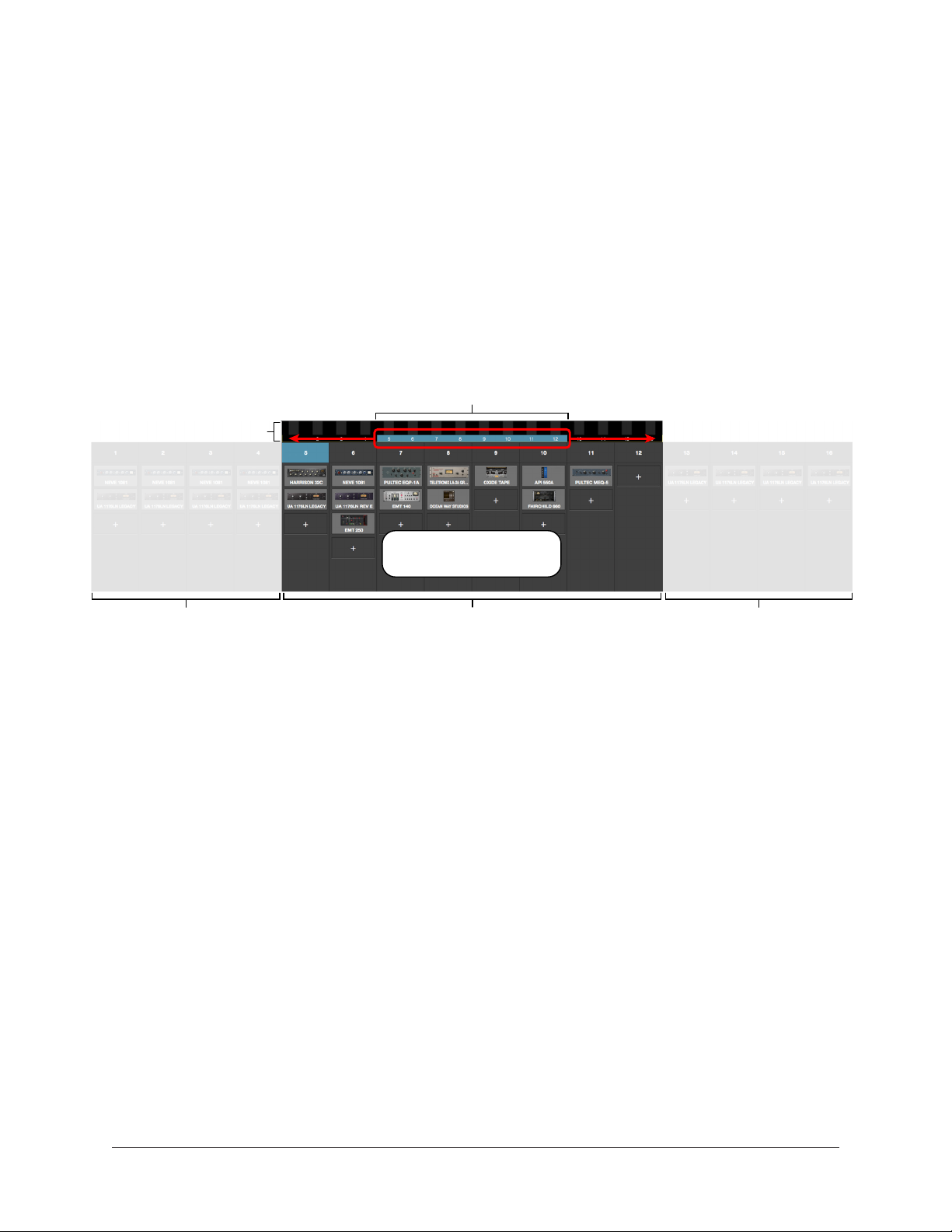
Banks
A fundamental navigational concept in Live Rack is the Bank. A Bank is a subset of all
available MADI channels.
Current Bank
The Current Bank is all the channels displayed in the Channels Bar. Channels contained
within the Current Bank are represented by the Channel Select Buttons and the thin blue
Bank Bar.
The Current Bank is changed by sliding the blue Bank Bar, clicking an Input Meter, or
using the computer’s arrow keys. The number of Current Bank channels can be changed
with the Bank Size setting. For details, see “Bank Navigation” on page 52.
Bank Bar (blue)
Meter Bridge
Slide blue Bank Bar
to change visible channels
Current Bank (visible channels)Channels outside Current Bank Channels outside Current Bank
Conceptual illustration of a Bank within Live Rack.
In this example, the Current Bank is channels 5 through 12.
Dragging the thin blue Bank Bar brings the other channels into view.
UAD‑2 Live Rack Manual Chapter 4: Live Rack Application 45
Page 46

Navigation Scroll Bars
Live Rack software displays vertical and horizontal scroll bars when needed in various
views. Scroll bars are used for navigation in the following areas:
• Channel View / Single view mode – For horizontal and/or vertical scrolling of a
plug‑in interface that is too large for the current screen resolution to display.
• Channel View / Channel Strip view mode – For horizontal and/or vertical scrolling
of a Channel Strip that is too large for the current screen resolution to display
• All list views – Plug‑in presets, channel presets, assign, snapshots, and settings/
plug‑ins tab – For vertical scrolling of all files/folders in the current list view.
Typical navigation scroll bars, shown here outlined in red, as they appear
with a typical plug-in interface and in the Snapshots list
UAD‑2 Live Rack Manual Chapter 4: Live Rack Application 46
Page 47

Keyboard Focus
When elements on the screen have keyboard focus, they can be manipulated with the
computer’s QWERTY keyboard. Focused items can typically be manipulated by using the
up/down/left/right arrow keys and/or the Return/Enter keys.
Focus Indication
Keyboard focus in Live Rack is indicated by a yellow outline box around screen elements
targeted for control with the QWERTY keyboard.
Typical focus indication. In this example, the PRESETS folder column on the left has
focus (yellow outline) and can be navigated with the up/down arrow keys on the keyboard.
The tab key will shift focus between this column and the SUB-FOLDER column.
Focus Navigation
Focus between elements can be changed with the computer’s TAB key, or by clicking
another area of the screen with the mouse.
UAD‑2 Live Rack Manual Chapter 4: Live Rack Application 47
Page 48

Keyboard Shortcuts
In addition to keyboard focus/navigation methods, Live Rack supports the keyboard
shortcuts listed in the table below.
Shortcut Name Keyboard Command Description
Save Snapshot COMMAND+S Saves the current snapshot in place
Save Snapshot As... COMMAND+SHIFT+S Saves the current snapshot as a new snapshot
and allows renaming
Hide Application COMMAND+H Hides the application from view
Quit Application COMMAND+Q Quits the Live Rack application
Show Previous View* COMMAND+LEFT ARROW Returns to the previous view
Show Next View* COMMAND+RIGHT ARROW Returns to the next view
Tab Focus Navigation TAB Cycles through various sections of the app that
can be focused/controlled/navigated with the
arrow keys
Cancel dialog overlay ESC (escape) Used to cancel dialog functions like Save As,
Tap Tempo, enter Edit Mode, etc.
Confirm dialog overlay RETURN or ENTER Used to accept dialog overlays like Save As, Tap
Tempo, enter Edit Mode, etc.
Channel Navigation UP/DOWN/LEFT/RIGHT
RETURN/ENTER
*Previous/Next only shows Views displayed since application was opened
Used to navigate through all channels and
functions that can be focused and executed
Important: Live Rack does not have an Undo function. Operations performed
in Edit mode can only be reverted by loading previously-saved presets and/or
Snapshots.
UAD‑2 Live Rack Manual Chapter 4: Live Rack Application 48
Page 49

Global Screen Elements
The Main Column, Current Bank, Meter Bridge, Channel Bar, and Info Bar are groups of
elements appear on all screens. These global elements are described in this section.
Refer to the illustration below for descriptions in this section.
Main
Column
Bank Bar
(blue)
Current
Bank
Elements displayed in this area
depend on the currently selected View
Meter
Bridge
Channels
Bar
View
Elements
Info Bar
Global elements that appear on all Live Rack screens
View Elements
The View elements that appear in the main area of each View screen (items not within
the Main Column, Meter Bridge, Channels Bar, or Info Bar) depend on the View that
is currently selected. All View elements are described in the View sections later in this
chapter.
UAD‑2 Live Rack Manual Chapter 4: Live Rack Application 49
Page 50
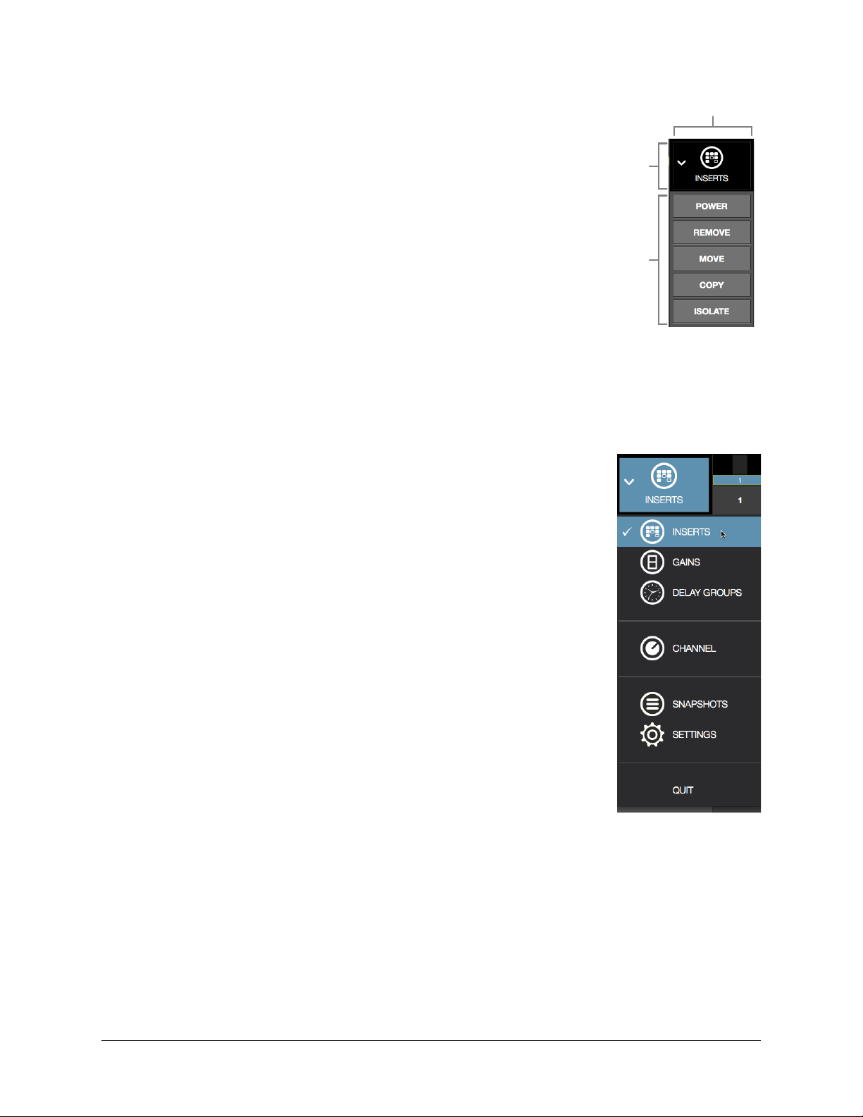
Main Column
The Main Column is used to choose the current View and
navigate available options within the View. The Main Column
contains the View Menu and the View Options, as shown at right.
In the illustration at right, Inserts View is currently active. This is
indicated by the INSERTS icon and title at the top of the Main
Column.
Main
Column
View
Menu
The View Options shown here are the options available in Inserts
View. These options are different for each active View.
View
Options
Column Placement
By default, the Main Column is at the left side of all screens.
However, its placement can be moved to the right side of all
screens, by setting the preference at View Menu>Settings>Display Tab>COLUMN
LOCATION.
View Menu
The six main Views can be accessed with the View Menu. To
access any View, click the View Menu at the top of the Main
Column, and select a View from the drop menu, as shown at right.
View Options
The View Options are buttons used to activate various control
functions within each View. The View Options displayed are
contextual; the options change when a different View is selected.
Bank Views
Bank Views are Views that display multiple channels at once.
Inserts, Gains, and Delay Groups are the three Bank Views. The
Bank Views are grouped within the View Menu; they are not
separated by a divider line.
Shortcut: On any screen, click the Meter Bridge to quickly
return to the last selected Bank View.
Quit
At the bottom of the View Menu is the QUIT option. Choose QUIT
to close the Live Rack application. The Command+Q keyboard
shortcut can also be used.
UAD‑2 Live Rack Manual Chapter 4: Live Rack Application 50
View Menu
Page 51

Meter Bridge
The Meter Bridge is always displayed across the top of all screens. The Meter Bridge
contains Input Meters for all MADI channels in the system and can be used for
navigation within Live Rack.
Mono
Channel
Meter
Stereo
Channel
Meter
Bank Bar
(blue)
Signal
Present
(green)
No
Signal
(black)
MADI Channel
Number
Channel
Input
Level
Meters
Meter Bridge elements as displayed with a 16-channel (single unit) system
Input Meters
Each vertical green meter indicates input signals that are present in the associated MADI
channel. The Meter Bridge automatically expands to display additional MADI channels
when two, three, and/or four Live Rack hardware units are connected to the system.
Shortcut: Single-click the Input Meters to enter the most recently selected bank
view.
Additional (empty) MADI channels can be manually added to the Meter Bridge by
clicking the “+” button at View Menu>Settings>Hardware Tab. This provision is typically
used to add empty MADI channels so offline setups can be configured.
Mono/Stereo
A dual/split meter indicates two channels are stereo linked. When a dual/split meter is
shown, the meter represents the left and right channels of the stereo signal.
Meter Bridge Navigation
The Meter Bridge can be used as shortcuts for the functions below:
• Jump to any channel – Double click any channel’s Input Meter in the Meter
Bridge to jump directly to Channel View and select the channel.
• Return to Bank View – Single click anywhere in the Input Meters area to return to
the previously selected Bank View (Inserts, Gains, or Delay Groups).
UAD‑2 Live Rack Manual Chapter 4: Live Rack Application 51
Page 52

Channels Bar
The Channels Bar is used for channel navigation and to quickly select channels for
editing. Refer to the illustration below for descriptions in this section.
Current Bank
Stereo
(linked)
Channel
Channel
Select
Buttons
Channel
Name &
Number
Selected
Channel
(blue button)
(channels within the Bank Bar)
Bank Bar (blue)
Unselected
Channel
(gray buttons)
Channels Bar elements as displayed with a Bank Size of 8 channels
Current Bank
The Current Bank is all the channels displayed in the Channels Bar, and is a subset of all
available MADI channels. Channels contained within the Current Bank are represented
by the Channel Select buttons and the thin blue Bank Bar.
The Current Bank is changed can be changed with several Bank Navigation methods. The
number of Current Bank channels can be changed via the Bank Size setting.
Bank Size
The number of channels displayed simultaneously in the Current Bank is determined
by the Bank Size setting, which is specified in View Menu>Settings>Display Tab>BANK
SIZE.
Bank Bar
The thin blue Bank Bar represents all channels in the Current Bank. The Bank Bar is
used for Current Bank navigation within all View screens.
Bank Navigation
The Bank Bar is used to change the Current Bank. Any of the following methods can be
used to navigate available channels:
• Drag – Drag the blue Bank Bar, or anywhere in the Input Meters area, with the
mouse to change the current bank. With this method, the current bank can be
shifted by one or more channels.
• Click Input Meter – Single click any channel’s green input meter to switch directly
to the bank that contains the channel. With this method, the number of channels
shifted is determined by the BANK SIZE setting.
• Arrow keys – When the Bank Bar has keyboard focus, use the left/right arrow keys
to shift the current bank. With this method, the number of channels shifted is
determined by the BANK SIZE setting.
UAD‑2 Live Rack Manual Chapter 4: Live Rack Application 52
Page 53

Channel Select Buttons
The Channel Select buttons represent all Current Bank channels. The Channel Select
buttons are displayed in all Bank Views (Inserts, Gains, and Delay Groups).
The Channel Select buttons can be used to quickly put any Current Bank channel into
Channel View for loading, editing, and saving plug‑in settings.
Shortcut: Single-click any bank channel select button to enter Channel View and
select the channel for plug-in editing.
Channel Number & Name
The channel number and name is displayed in each Channel Select button. If no channel
name has been entered, only the channel number is displayed. The channel number
cannot be modified.
Channels are named in Channel View by clicking the channel’s Channel Name Button
within the Main Column, then entering a name in the name field that appears.
Selected Channel
The currently selected channel within the Current Bank is highlighted by a blue Channel
Select button. Functions in Channel View are always performed on the selected channel.
UAD‑2 Live Rack Manual Chapter 4: Live Rack Application 53
Page 54

Info Bar
The Info Bar is always displayed in all screens, providing visual feedback and access to
options that are important in performance environments.
Refer to the illustration below for all Info Bar descriptions in this section.
Operating Mode
(Edit or Safe)
Active Snapshot
(italics = modified)
Clock Source
Display & Menu
Elements within the Info Bar
Active Tempo (BPM)
Display & Menu
Resource Display
(UAD plug‑in gauges)
The Tempo and Operating Mode controls can only be accessed via the Info Bar. All other
controls are also available elsewhere in the application. The Resource Display has no
controls (it is a visual indicator only).
Info Bar Placement
By default, the Info Bar is at the bottom of all screens. However, its placement can be
moved to the top of all screens, by setting the preference at View Menu>Settings>Display
Tab>INFO LOCATION.
Info Bar Elements
The Info Bar contains the five main elements below. All elements are described in greater
detail later in this section.
• Operating Mode – Displays the active Operating Mode (either EDIT or SAFE). Click
this area to switch modes.
• Active Snapshot – Displays the Active Snapshot name. If the snapshot has been
modified since it was loaded, the name is displayed in italics. If the Snapshot was
loaded via a Soundcraft Vi Console, the name is “[SOUNDCRAFT CUE].”
Shortcut: Click this area to switch to Snapshots View to load and/or save
Snapshots.
• Clock Source – Displays the active clock source (MADI, Word Clock, or Internal).
Click this area to select a different clock source from the drop menu. This area
flashes red if the currently selected clock signal is not detected (when digital
audio is not synchronized).
• Active Tempo – Displays the tempo, in beats per minute (BPM), used by UAD
plug‑ins that are set to use Tempo Sync. Click this area to enter or tap a different
tempo.
• Resource Meters – Displays resource loads used by UAD plug‑ins. This allows you
to monitor UAD loads as needed, for example when deciding which UAD plug‑ins
to load, based upon how much DSP is available.
UAD‑2 Live Rack Manual Chapter 4: Live Rack Application 54
Page 55

Operating Mode
Live Rack has two switched operating modes: EDIT and SAFE.
EDIT Mode
Edit mode is typically used for setup and configuration. Edit mode allows all
functionality, no matter how potentially destructive, to be executed.
Ideally, settings that can only be modified in Edit mode are set before a live performance
to minimize the risk of level changes, clicks/pops, or other audio artifacts that could
occur with some operations.
SAFE Mode
Specific parameters and/or functionality are inactive or disabled in Safe mode. This
mode is typically used during live performance to prevent inadvertent changes that could
significantly impact the audio. See the table on page 56 for the specific Safe mode
constraints.
Operating Mode Display
The active Operating Mode is displayed at the far left of the Info Bar.
The appearance of each active mode is shown at right.
Note: The Info Bar is the only area within Live Rack where the
Operating Mode can be viewed or changed.
Changing the active operating mode
To switch the active operating mode, single click anywhere in the Operating Mode display
element at the left of the Info Bar. Execution occurs as follows:
• Edit mode to Safe mode – When EDIT mode is active, clicking the operating mode
display instantly switches Live Rack into Safe mode.
• Safe mode to Edit mode – When SAFE
mode is active, clicking the operating mode
area presents a confirmation dialog to
prevent inadvertent mode switching. Click
OK in the dialog to confirm the change and
enter Edit mode.
UAD‑2 Live Rack Manual Chapter 4: Live Rack Application 55
Page 56

Safe Mode Constraints
View screen operations that cannot be executed in Safe mode are detailed in the table
below.
Caution: When Safe mode is active, Snapshots can still be recalled, which can
potentially overwrite current plug-in assignments and cause audio artifacts during
a live performance.
View Screen SAFE Mode Constraint
• Plug‑in REMOVE, MOVE, and COPY/PASTE modifiers are hidden
INSERTS
GAINS • Stereo LINK/UNLINK buttons are hidden
DELAY GROUPS
CHANNEL
SETTINGS • Sample Rate, Clock Source, and MADI Channels cannot be modified
INFO BAR • Clock Source cannot be modified
• Empty plug‑in inserts are hidden
• ASSIGN mode is disabled
• Latency compensation engine cannot be modified (existing settings persist)
• Delay Group buttons are hidden (existing groups persist)
• Channel ASSIGN tab is hidden
• Plug‑ins cannot be added or removed
• Channel PRESETS tab is hidden (when in Channel Strip mode)
• New Channel Strip presets cannot be added or removed
Snapshot Display
The Snapshot Display shows the filename of the Active
Snapshot.
A Snapshot is a complete Live Rack configuration file,
containing all parameter values within the application. Snapshots are typically used for
total session recall. Snapshots can also be recalled via MIDI or from within a Soundcraft
Vi console via Ethernet.
Italic Snapshot Name
Whenever the active snapshot is modified from its last
saved state, the Snapshot name is displayed in italics,
as shown at right.
Tip: Type Command+S at any time to save the current state of the existing
Snapshot to disk (overwriting the existing file; note this operation cannot be
undone), or type Shift+Command+S to save the Snapshot as a new disk file.
UAD‑2 Live Rack Manual Chapter 4: Live Rack Application 56
Page 57

Soundcraft CUE Name
When a Snapshot is loaded remotely from a Soundcraft
Vi Console (via Ethernet), the Active Snapshot is
overwritten. When this occurs, [SOUNDCRAFT CUE] is
displayed, as shown at right.
Caution: When a Snapshot CUE is loaded from a Soundcraft Vi Console, the Active
Snapshot is overwritten, any unsaved changes are lost, and audio artifacts could
occur.
Clock Display
The Clock Display has three functions: It shows the currently
selected clock source, facilitates selection of a different clock
source, and indicates when the selected clock source signal is not
detected.
Clock Source Menu
UAD‑2 Live Rack can synchronize to external MADI clock, external
word clock, or internal clock. To select a clock source, click
anywhere in the clock display area to view the clock source pop‑up
menu (shown at right), then select a clock source from the menu.
Tip: The clock source can also be specified in View
Menu>Settings>Hardware Tab>CLOCK SOURCE.
In typical use, UAD‑2 Live Rack should be set to MADI clock (the default value) for
synchronization with the digital audio from/to the MADI device.
Note: The Clock Source cannot be modified in SAFE mode.
No External Clock
If the Clock Source setting in not set to Internal and the external
clock signal cannot be detected and/or resolved, then the text
in the Clock Display display flashes RED (shown at right) until a
valid clock is detected and/or an alternate clock source is selected. If this occurs, verify
connections and external device settings.
Important: Only one device in a digital audio system can be the master clock
source. The UAD-2 Live Rack clock setting, and the sample rate, must match the
MADI device settings or audio artifacts could occur.
No Hardware Detected
If the UAD‑2 Live Rack hardware unit(s) is not properly connected
and/or the software is not properly installed, the clock source will
display OFFLINE as shown at right.
UAD‑2 Live Rack Manual Chapter 4: Live Rack Application 57
Page 58

Tempo Display
This area displays the tempo value of the Active Snapshot in BPM
(beats per minute) and facilitates selection of a different tempo.
The tempo value is used by time‑based UAD plug‑ins (such as delays and echos) that are
set to use their Tempo Sync features. For details about how to use UAD plug‑ins with this
feature, see “Tempo Sync” on page 137.
The Tempo value is stored within the Snapshot; therefore each Snapshot can contain
a unique tempo. The available tempo range is from 1.00 BPM to 999.00 BPM. The
default tempo of a new Snapshot is 120 BPM.
Changing tempo values within the tempo dialog
The tempo can be changed within the tempo dialog by
entering a text value or using the tap tempo feature.
To view the tempo dialog (shown at right), click anywhere
in the Tempo Display within the Info Bar.
Tip: To leave the tempo unchanged after entering an
(unwanted) value in the dialog, press the ESC key or
click Cancel with the mouse.
Text Entry
1. Open the tempo dialog by clicking the tempo display in the Info Bar
2. Type a numeric tempo value
3. Press Return or Enter, or click OK with the mouse.
Tap Tempo: QWERTY keyboard
1. Open the tempo dialog by clicking the tempo display in the Info Bar
2. Press the Tab key once to focus the TAP button (yellow outline)
3. Press the “t” key at least four times to establish the tempo
4. Press Return or Enter.
Tap Tempo: Mouse
1. Open the tempo dialog by clicking the tempo display in the Info Bar
2. With the mouse, click the TAP button at least four times to establish the tempo
3. Click the OK button.
UAD‑2 Live Rack Manual Chapter 4: Live Rack Application 58
Page 59

Changing tempo values via MIDI
Tap tempo can be used to set a new tempo from incoming MIDI that is received via the
macOS operating system. This method requires any external MIDI hardware and/or MIDI
software that is recognized by Audio MIDI Setup, which is macOS’s MIDI routing utility
application (located in /Applications/Utilities).
About external MIDI tap tempo control
• Audio MIDI Setup must be configured before Live Rack is launched. After it is
properly configured, Audio MIDI Setup does not need to remain open.
• MIDI note values or MIDI controller values can be used as the data source.
• Live Rack cannot synchronize the tempo to incoming MIDI beat clock.
MIDI configuration/setup
1. Before Live Rack is opened, verify the MIDI output device and/or MIDI software is
configured properly and active in Audio MIDI Setup.
2. In the View Menu>Settings>MIDI Tab (page 115), set the values for MIDI
DEVICE, MIDI CHANNEL, DATA TYPE, and DATA VALUE to match the transmitted
MIDI data.
3. Transmit the MIDI note or controller (as specified in the previous step) at least
four times to establish the tempo. The Tempo Display is RED during this period.
4. After a new tempo value is established, the new tempo is used and the Tempo
Display changes back to BLACK. Simply retransmit the MIDI data to apply further
tempo updates.
UAD‑2 Live Rack Manual Chapter 4: Live Rack Application 59
Page 60

Resource Display
UAD plug‑in loads are shown in the Resource Display at the far right of the Info Bar.
These three meters (DSP, PGM, and MEM) provide important visual feedback in realtime,
by helping to determine which plug‑ins to load if available UAD resources are limited.
Program Memory Meter
DSP Meter Memory Meter
Resource Display within the Info Bar
The Resource Display mirrors the meters within the UAD Meter & Control Panel
application. The details provided in this section is a subset of more complete
explanations that are available in “Chapter 5: UAD Meter & Control Panel” beginning on
page 120.
UAD Resource Loads
The green bar graph of each meter, and its percentage, represent the amount of the
resource that is currently used. 100% is the maximum possible load.
Averaged Loads
The load for each meter represents the average for all UAD devices in use. For example,
if one Live Rack hardware unit is installed, the DSP load is an average of the four
SHARC DSP processors in the unit. If two units are installed, then the loads of all eight
processors are averaged.
Channel Loads
Important: All UAD plug-ins in a single channel must fit on a single DSP.
Therefore it is possible to get a “plug-in was unable to load” message when
attempting load a plug-in or in a channel that does not have enough UAD
resources, even if the Resource Display indicates enough overall resources are
available.
Static Loads
UAD‑2 Live Rack uses UAD DSP and memory for its internal DSP mixer, therefore the
meters will indicate loads (when the hardware is connected) even if UAD plug‑ins are not
loaded.
Individual Device Loads
The loads of individual devices in a multi‑unit setup, and the individual DSP loads within
a single unit) can be viewed in the System Information panel within the UAD Meter &
Control Panel application.
UAD‑2 Live Rack Manual Chapter 4: Live Rack Application 60
Page 61

UAD Plug-Ins Loads
The amount of UAD resources used by UAD plug‑ins vary with each individual plug‑in;
more complex algorithms require more resources.
The amount of DSP used by each individual UAD plug‑in is available in the UAD
instance count chart. The chart can help determine which to plug‑ins to assign with
available resources. The chart is published online at:
• help.uaudio.com/hc/en‑us/articles/215262223
DSP
The DSP meter displays the amount of digital signal processing resources that are being
used by UAD‑2 Live Rack. DSP is the primary hardware resource that powers the UAD
plug‑in algorithms.
Note: When UAD plug-ins are disabled, DSP requirements are decreased EXCEPT
when the plug-in is disabled using the Power control within the plug-in interface.
Program
This resource meter shows how much program memory (PGM) is in use. Program memory
is an on‑chip memory that is specific to the SHARC processor(s) and is used for certain
UAD plug‑in resources.
Each unique UAD plug‑in uses a bit of program memory. If many different plug‑ins are
loaded simultaneously, it is possible for this resource to run out before a DSP overload
occurs. This point is considered and factored in by automatic load balancing routines.
Memory
The Memory (MEM) meter indicates the amount of UAD‑2 Live Rack hardware RAM that
is currently in use.
Memory is used for echo, delay lines, reverb, and similar spatial processing. When UAD
plug‑ins are disabled but not unloaded, memory requirements are not decreased. In this
case, the memory remains loaded so that reverb tails and delay lines are not cut off when
the plug‑in is disabled.
UAD‑2 Live Rack Manual Chapter 4: Live Rack Application 61
Page 62

Inserts View
Inserts View displays an overview of the current state of all inserts within all channels
within the Current Bank. An insert is a single slot, within a single channel, where UAD
plug‑ins are instantiated.
This view is where plug‑ins can be very rapidly disabled, moved, removed, copied, and
isolated using the Inserts Options. All Inserts View functions are detailed in this section.
Inserts
Option
Buttons
Channel
Column
Disabled Insert
(red/italic)
Active Insert
(light gray)
Current Bank Channels
Inactive Insert
(blue/italic)
Empty
Insert Slot
(+)
Channel
Insert
Slots
Channel
Output
Meters
Main elements within Inserts View
Inserts View is one of the three Bank Views. If Inserts View is active then a non‑Bank
View (Channel, Snapshots, or Settings) is activated, single‑clicking the input meters in
the Meter Bridge will return to Inserts View.
Current Bank Channels
Inserts View displays all channels in the Current Bank. The Current Bank is defined by,
and navigated with, the blue Bank Bar within the Meter Bridge.
Tip: To change the active bank channels, focus the Bank Bar via the Tab key then
use the left/right arrow keys, or drag the Bank Bar with the mouse.
Bank Size
The total number of channels displayed concurrently in the active bank is a preference
specified in View Menu>Settings>Display Tab>BANK SIZE.
UAD‑2 Live Rack Manual Chapter 4: Live Rack Application 62
Page 63

Channel Column
The channel column provides an overview of the plug‑in state
of a single channel, and all channels in the bank are displayed
concurrently. All UAD plug‑ins loaded in the channel are
displayed here, along with an output meter for the channel.
Note: The number of displayed channel columns is defined
by the bank size setting in Settings View.
Insert Slots
The insert slots indicate the current status of each plug‑in, and
provide a shortcut to Channel View, where the individual plug‑
ins are manipulated. Up to eight slots are available within each
channel to facilitate serial signal processing.
Shortcut: Click anywhere in any empty column space to jump
to Channel View for assigning and editing plug-ins in the slot.
Channel Signal Flow
Audio signals in a channel flow through the inserts serially from
top to bottom. Therefore, if more than one plug‑in is inserted in
a channel, the location of a plug‑in within the inserts can impact
the sound of the channel. Inserts can be re‑ordered in Channels
View to change the serial processing order.
State Indication
Populated insert slots contain a thumbnail image of the UAD
plug‑in that is loaded in the slot. The state of loaded plug‑ins
within each insert slot can be determined by the background
color of the slot, as follows:
Active (light gray) – The plug‑in is active and processing audio.
Inactive (dark blue) – The plug‑in has been disabled by the
power button in Channel View, and the plug‑in name is italicized.
The EMT 140 slot at right illustrates this state.
Channel column with
populated insert slots
Note: Disabling a plug-in via the power control within its graphical interface
(versus the Power button in Channel View) does not change the background color
or italicize the name.
Disabled (red) – The plug‑in is disabled because there is not enough UAD resources, it is
unlicensed and the demo has expired, and/or the UAD authorization needs updating. The
plug‑in name is also italicized. The EP‑34 slot at above right illustrates this state.
Empty (+) – The slot is not populated with a plug‑in. Click the”+” symbol to switch to
Channel View and insert a plug‑in into the slot.
Tip: Click anywhere in any empty column space to insert a plug-in at that location.
UAD‑2 Live Rack Manual Chapter 4: Live Rack Application 63
Page 64

Output Meter – This meter displays the signal level at the output of the channel (after all
plug‑in processing in the channel).
Inserts Options Overview
The Inserts Options (in the Main Column, below the View Menu)
enable various operations to be performed on the plug‑ins displayed
within Inserts View.
The option operations are accomplished by selecting an option to
latch the function, executing the operation(s) using Modifiers, then
exiting the latched function.
Option Latch
When an Inserts Option button is activated, the
button flashes blue, indicating that the function is
latched and ready to be executed.
Option Unlatch
The latched option is unlatched (the button stops flashing blue) when:
• Any option button is activated (same or different)
The Inserts
Options buttons
• A different View screen is activated
• No operations are executed during the Timeout Length
Timeout Length
When an option is latched, it is automatically unlatched (times out) after the Timeout
Length to prevent inadvertent modifications. The Timeout Length is a preference set in
View Menu>Settings>Display Tab>TIMEOUT LENGTH. The default Timeout Length is six
seconds.
Modifiers
Modifiers are icons superimposed on various elements when an option is latched.
Modifiers are used to execute the operations. The specific modifiers that appear, and
where they are located, depend upon the specific option that is latched.
Inserts modifiers are superimposed on insert slots, and smaller column modifiers are
superimposed on the Channel Select buttons within the Channels Bar, as shown in the
next screenshot.
Modifier Swipe Shortcuts
Modifier functions can be executed extremely rapidly across many channels and/or insert
slots in the current bank using the swipe shortcuts. When an Insert Option is latched,
click+hold the mouse, then drag vertically and/or horizontally across channels and/or
inserts to perform the function on all inserts that are swiped.
Tip: The Modifier swipe shortcuts are (by far) the fastest way to perform the same
function on multiple inserts (for example, as compared to equivalent functions in
Channel View).
UAD‑2 Live Rack Manual Chapter 4: Live Rack Application 64
Page 65

Inserts View showing the modifiers that appear when the move option is latched. Swipe
across channels and/or insert slots to rapidly perform the function on many inserts.
Inserts Option Descriptions
The functions of each Insert Option are detailed below. The descriptions and screenshots
are applicable when the option button is latched (blue).
Important: All UAD plug-ins within a single channel must fit on a single DSP.
Therefore it is possible to get a “plug-in was unable to load” message when
attempting to move or paste a plug-in or channel strip to a channel that does
not have enough UAD resources, even if the Resource Display indicates enough
overall resources are available.
Most Inserts Options are only available in EDIT mode. The Power and Isolate options are
available in SAFE mode.
Important: Insert Option operations cannot be undone.
UAD‑2 Live Rack Manual Chapter 4: Live Rack Application 65
Page 66

Power
The Power option deactivates an individual plug‑in
within a single insert slot. When deactivated, the
plug‑in no longer uses UAD DSP resources. Click the
modifier to change the power state.
When Power is latched, deactivated plug‑ins are
indicated by a red modifier, and active plug‑ins have a
green modifier.
Caution: Because this function unloads and loads the plug-in from the DSP, audio
artifacts can occur if the power state is changed while audio is being processed by
the plug-in. To disable individual plug-in processing without audio artifacts, use
the power control within the plug-in interface in Channel View instead (however,
the interface control method does not reduce DSP loads).
Remove
The Remove option permanently deletes the plug‑in
from the insert slot. When Remove is latched, click the
modifier to delete the plug‑in.
Important: If the plug-in settings are modified and
unsaved in a preset, the modified settings are lost
with this function (Remove cannot be undone).
Caution: Because this function unloads the plug-in from the DSP, audio artifacts
can occur if a plug-in is removed while audio is being processed by the plug-in.
Move
The Move option is used to move an individual plug‑in
(and its active settings) from one insert slot to another
insert slot in any channel within the Current Bank.
Move can also be used to move a complete channel
strip (all plug‑ins in the channel column) from one
channel to another channel within the Current Bank.
Move Individual Plug-In
When Move is latched, drag any insert modifier to move
the plug‑in to another slot. If a plug‑in exists in the destination slot, the existing plug‑in
is bumped to a different slot within the same channel.
Move Channel Strip within same bank
When Move is latched, drag any column modifier (above the plug‑in inserts) to another
channel to move the all plug‑ins in the source column to the destination column.
Important: If plug-ins exist in the destination channel, all existing plug-ins in the
destination channel are deleted. Move operations cannot be undone.
UAD‑2 Live Rack Manual Chapter 4: Live Rack Application 66
Page 67

Copy
The Copy option is used to duplicate an individual
plug‑in (modifier on plug‑in insert) or complete channel
strip (modifier above inserts), and their active settings.
Copy can be performed from one insert slot to another
insert slot (on the same or a different channel), or from
one channel to another channel, within the Current
Bank.
Note: To copy settings to a channel that is not
within the current bank, use the channels presets
function available within Channel View.
Copy is a two step process. First the insert or channel strip is copied, then the copied
data is pasted to the destination insert or channel.
Tip: After copying, the copied modifier remains superimposed on the source
element, as an indicator of the data that resides in the copy/paste buffer.
Paste
After any insert or channel strip is copied, the Copy button changes to
Paste. To paste the copied data, click any insert slot and the copied
data is placed in the destination. The copied data can be pasted to
multiple destinations as long as the paste option remains latched.
Important: If plug-in or channel strip exists in the paste destination(s), existing
plug-ins or channel strips in the destination(s) are deleted. Paste operations
cannot be undone.
Copy Individual Plug-In
When Copy is latched, click any insert modifier to copy the plug‑in, then click one or
more destinations while the paste button is latched.
Copy Channel Strip
When Copy is latched, click any column modifier to copy the channel strip, then click
one or more bank channel select buttons while the paste button is latched.
Note: When copying channel strips, the channel’s input and output gain settings
are also copied/pasted to maintain consistent signal levels.
UAD‑2 Live Rack Manual Chapter 4: Live Rack Application 67
Page 68

Isolate
Isolate prevents a channel’s active settings from being modified when a Snapshot (a Live
Rack configuration file) is loaded.
Isolate is typically used to prevent channel adjustments made during a live performance
from being overwritten by Snapshot changes.
When Isolate is latched, click any column modifier to isolate the channel. Click again to
de‑isolate the channel.
When a channel is isolated, the text “[ISO]” appears beneath the bank channel name in
the Meter Bridge.
Tip: Channel isolations can also be set in Gains View.
Isolate modifiers and text indication
UAD‑2 Live Rack Manual Chapter 4: Live Rack Application 68
Page 69

Gains View
Gains View displays input/output gain level controls, and signal input/output level
meters, for all channels within the Current Bank. Channels can also be stereo linked and
unlinked in this view.
Refer to the illustration below for all Gains View functions detailed in this section.
Gains
Option
Buttons
Channel
Column
Unlinked
Channel
(mono)
Linked
Channel
(stereo)
Gain
Elements
(faders+others)
Gain
Faders
Link &
Unlink
Buttons
Current Bank Channels
Main elements within Gains view
Bank View
Gains View is one of the three Bank Views. If Gains View is active then a non‑Bank View
(Channel, Snapshots, or Settings) is activated, single‑clicking the input meters in the
Meter Bridge will return to Gains View.
Channel Column
The channel column can display input channels, output channels, or both input and
output channels, depending on the Gains Option that is specified.
Bank Channels
As with all Bank Views, the number of channel columns displayed in Gains View is
defined by the Current Bank, which can be changed by moving the blue Bank Bar in the
Channels Bar.
UAD‑2 Live Rack Manual Chapter 4: Live Rack Application 69
Page 70

Gain Elements
Each input and output channel has its own set of gain controls and indicators. Refer to
the illustration below for descriptions of the elements that follow.
I/O
Type
Display
Fader
Handle
Link
Button
Unlinked
Channel
(mono)
Gain elements
Linked
Channel
(stereo)
Gain
Value
Display
Gain Fader
&
Level Meter
Unlink
Button
Channel
Number
& Name
I/O Type
The IN or OUT text is a label that indicates whether the gain controls are for an input
channel or an output channel. Each row of gain controls is always of the same. If the
BOTH option is active, input gain controls are above the output controls.
Gain Value
This field displays the current gain setting in dB, with one‑tenth dB resolution. The value
is changed by moving the fader handle.
Gain Fader
The gain faders are used to set the gain of the I/O channels. Drag the fader handle to
change the gain value.
The available gain range for all I/O gain faders is from –INF dB to 12 dB. The default
value is 0 dB (unity gain).
Tip: Option+click any gain fader (or anywhere within a channel column) to set its
gain to 0 dB. This operation cannot be undone.
UAD‑2 Live Rack Manual Chapter 4: Live Rack Application 70
Page 71

Input Faders
The input faders adjust the level of the MADI signal before plug‑in processing.
Tip: By adjusting the input gain, different sonics can be obtained with UAD plugin emulations that have (desirable) non-linear input distortion characteristics.
Output Faders
The output faders adjust the level of the MADI signal after plug‑in processing. Output
adjustments are convenient to compensate for overall level changes that may occur
within a plug‑in or channel strip.
Fader Handle
Gain values are adjusted with this control. Drag the handle down to lower the gain, or up
to increase the gain.
Level Meter
The digital signal level of the channel is represented here in green, using standard digital
peak metering. The top of the meter range indicates 0 dBFS (digital full scale). The top
bar glows RED when 0 dBFS is exceeded (when digital clipping has occurred).
Note: The fader handles are superimposed on the level meters. Therefore, the
signal may appear above the handle position.
Input Meters
The input meters are pre‑fader. The incoming MADI channel’s signal level is displayed.
Output Meters
The output meters display the MADI channel’s output level after plug‑in processing but
before the output fader (post plug‑ins, pre‑fader).
Channel Number & Name
The channel number and name is displayed here. If no channel name has been entered,
only the channel number is displayed (the channel number cannot be modified).
Tip: Channels are named in Channel View by clicking the channel’s number/name
box within the Main Column, then entering a name in the name field that appears.
Link/Unlink
Two adjacent channels can be combined into a stereo pair. When channels are linked, all
control adjustments affect both channels of the stereo signal identically.
Note: The link and unlink cannot be performed in SAFE mode. The link/unlink
buttons are hidden when SAFE mode is active.
Tip: Channels can also be linked/unlinked in Channel View by clicking the
channel’s number/name box within the main column.
UAD‑2 Live Rack Manual Chapter 4: Live Rack Application 71
Page 72

Activating Link
Stereo pairs are created by clicking the LINK button between two adjacent channels.
Important: When Link is activated, all channel and plug-in settings in the right
channel are overwritten by the plug-ins and gains in the left channel. This
operation cannot be undone.
When Link is activated:
• The LINK button text changes to UNLINK
• One set of controls is available for the stereo channel
• All current control settings of the left channel are copied to the right channel
• All inserted plug‑ins in the left channel are converted to stereo (parameter values
are retained)
• The level meter changes to a stereo level meter
Link Deactivation
The stereo pair is separated back into individual channels by clicking the UNLINK
button. When LINK is deactivated, all current control settings and inserted plug‑ins for
the stereo channel are copied to both resulting mono channels.
Link Constraint
Odd‑numbered channels can only be linked to the next even‑numbered channel (for
example, channel 1 can be linked to channel 2, but channel 2 cannot be linked to
channel 3).
Gains Options
The Gains Options (in the Main Column, below the View Menu) enable
various views to be changed, and operations to be performed, on the
channels displayed within Gains View.
View Options
The Inputs, Outputs, and Both options change the I/O channels that
are displayed. They do not use latching or modifiers.
Note: One of the view options is always active, including when a
latched option is being performed.
Latched Options
The Default and Isolate option operations are accomplished by
selecting the option to latch the function, executing the operation(s),
then exiting the function.
Gains Options
buttons
These latched options use the same methodology as Inserts View. For complete details
about latched operations, see “Option Latch” on page 64.
UAD‑2 Live Rack Manual Chapter 4: Live Rack Application 72
Page 73

Inputs
When the Inputs option is active (when the button is blue), only the input gains are
displayed. This option enables increased resolution of the gain faders and level meters by
increasing the vertical space devoted to the input channels (versus the Both option).
Outputs
When the Outputs option is active (when the button is blue), only the output gains are
displayed.
Tip: The Inputs and Outputs view options enable increased resolution of the gain
faders and level meters by increasing the vertical size of these elements.
Both
This view option displays all input and output gains in the Current Bank. The vertical size
of the gain faders is reduced in this view.
Default
This option facilitates the ability to quickly set one or more displayed gain levels to 0 dB
(unity gain). When the Default button is latched, click any gain fader (or anywhere within
a channel column) to set its gain to 0 dB.
Note that gain values can be returned to 0 dB without using the Default option. To set
a gain value to 0 dB within any screen in Gains View or Channel View, option+click any
gain fader.
Important: Gain changes using either of these methods cannot be undone.
Isolate
Isolate prevents a channel’s
active settings from being
modified when a Snapshot (a
Live Rack configuration file) is
loaded.
Isolate is typically used to
prevent channel adjustments
made during a live performance
from being overwritten by
Snapshot changes.
When Isolate is latched, click
any column modifier to isolate
the channel. Click again to
de‑isolate the channel.
When a channel is isolated, the
text “[ISO]” appears beneath the bank channel name in the Channels Bar.
Tip: Channel isolations can also be set in Inserts View.
UAD‑2 Live Rack Manual Chapter 4: Live Rack Application 73
Page 74

Delay Groups View
Delay Groups are latency compensation tools used to maintain phase alignment across
multiple channels when upsampled UAD plug‑ins are used in Live Rack.
Refer to the illustration below for element descriptions in this section.
Delay
Group
Options
Channel
Column
Active
Delay Group
Display
Inactive
Delay Group
(all gray buttons)
Active
Delay Group
(all blue buttons)
Delay
Group
Buttons
Samples
Display
Output
Meters
Current Bank Channels
Elements within Delay Groups View
Bank View
Delay Groups View is one of the three Bank Views. If Delay Groups View is active then a
non‑Bank View (Channel, Snapshots, or Settings) is activated, single‑clicking the input
meters in the Meter Bridge will return to Delay Groups View.
Channel Column
The elements displayed in the Channel Column is the same for all channels in the
Current Bank, and varies depending on the currently selected Delay Group Option.
Bank Channels
As with all Bank Views, the number of channel columns displayed in Delay Groups View
is defined by the Current Bank, which can be changed by moving the thin blue Bank Bar
within the Channels Bar.
UAD‑2 Live Rack Manual Chapter 4: Live Rack Application 74
Page 75

Delay Groups Overview
Upsampled UAD plug-ins
Some UAD plug‑ins are upsampled, meaning their internal sample rate is increased to
achieve sonic design goals. When upsampled UAD plug‑ins are loaded in Live Rack,
additional latency delay is induced in the channel(s) using the plug‑in(s).
Although the delay added by each upsampled UAD plug‑in is negligible (typically
between 0‑140 samples, depending on the plug‑in and sample rate), this extra delay can
affect output phase coherency.
For example, if two microphones are used on an acoustic source (such as a drum kit) and
an upsampled plug‑in is used on one of the mic channels but not the other, the phase of
the two mic channels will no longer be aligned.
Note: For the list of upsampled UAD plug-ins and their specific latency values,
see the UAD Plug-Ins Manual.
How Delay Groups work
Delay Groups automatically add small amounts of delay to each channel in the group
that are not delayed by upsampled plug‑ins, so all channels in the group are still phase
aligned. In other words, all channels in the Delay Group are delayed by the same
amount.
Note that the amount of delay added by the Delay Group engine is automatic. Only the
minimum amount of delay actually required to compensate the channel(s) is dynamically
applied, maintaining the lowest possible latency required for phase alignment at all
times.
Up to 16 unique Delay Groups can be configured. For specific instructions, see
“Configuring Delay Groups” on page 78.
When To Use Delay Groups
Delay Groups are required to maintain channel phase alignment only when both of these
conditions are met:
1. Multiple Live Rack channels are used for a single source (such as a drum kit using
multiple microphones), and
2. Any of those source channels contain upsampled UAD plug‑ins.
Latency compensation using Delay Groups is not needed for any these conditions (when
phase coherency is not imperative):
• When upsampled plug‑ins are not used on the same source
• When upsampled plug‑ins are used on different sources
System Latency
Overall system throughput latency with Live Rack is 73 samples when no plug‑ins are
assigned (and also through non‑upsampled plug‑ins).
UAD‑2 Live Rack Manual Chapter 4: Live Rack Application 75
Page 76

Delay Groups Options
The Delay Groups Options (in the Main Column, below the View Menu)
change which Delay Group buttons are displayed and changes the
amount of delay compensation that is available.
Delay Group Button Selectors
These buttons determine which Delay Group buttons are displayed in
the main screen area. Click these option buttons to display a different
set of Delay Group buttons.
The number of buttons that appear here, and their labels (1–8, 9–16,
etc), depend on the vertical resolution (pixel count) of the computer’s
display screen.
Higher resolution displays can show more Delay Group buttons simultaneously, therefore
fewer Delay Group buttons are shown in the Main Column in this case. With lower
resolution displays, less space is available for the Delay Group buttons, so more Main
Column buttons are available to switch between them.
Compensation Menu
This drop menu determines the maximum compensation delay, in samples, that is
available for each channel. Click the menu and select any value to change the setting.
Delay Groups
Options
Compensation Values
The available Compensation values are listed in the table below.
Delay Group Compensation Values
Setting Name Maximum Available Delay
Per Channel (samples)
OFF (Default) 0
SHORT 100
MEDIUM 200
LONG 1000
UAD Resource Usage
Use these guidelines when selecting values from the Compensation Menu:
• Off – When set to OFF, the delay compensation engine is disabled and the Delay
Group buttons are hidden.
• DSP – Delay Groups use a small percentage of DSP resources. To maximize DSP
resource availability for UAD plug‑ins, only use Delay Groups when necessary.
• Memory – Longer Compensation values use more Memory resources. To maximize
Memory resource availability for UAD plug‑ins, only the smallest value required.
Although UAD Memory resources are typically not constrained, overloading is
possible if many time‑based plug‑ins (reverbs and delays) are active.
UAD‑2 Live Rack Manual Chapter 4: Live Rack Application 76
Page 77

Delay Compensation Exceeded
If the maximum available delay compensation amount is exceeded on a channel when
inserting an upsampled plug‑in, a notification dialog appears. To maintain phase
alignment if this occurs, either increase the Compensation Menu value or reduce
upsampled plug‑ins usage on the channel.
Delay Groups Elements
Refer to the illustration on page 74 for descriptions in this section.
Active Delay Group Display
The Delay Group that the channel currently belongs to is always displayed
here. If the channel is not contained within any Delay Group, “Off” is
displayed here and the channel is not delay compensated.
A Delay Group number is displayed here by clicking one of the channel’s
numbered Delay Group buttons below the display.
Note: A channel cannot belong to more than one Delay Group.
Delay Group Buttons
There are 16 numbered Delay Group buttons and one OFF
button for each channel. Each Delay Group button represents
one of the 16 available Delay Groups.
Note: All Delay Group buttons are hidden when the
Compensation Menu value is set to OFF.
To add a channel to any Delay Group, click the numbered
Delay Group button in the Channel Column. The button is
highlighted in blue and the number is reflected in the Active
Delay Group display at the top of the channel column.
Note that unless the display monitor has a very high vertical resolution (pixel count), all
Delay Group buttons for an individual channel are not displayed concurrently. To view the
Delay Group buttons that are not currently visible, use the Delay Group Option buttons in
the Main Column.
Samples Display
The Samples display shows the sum of all extra samples (the total latency
delay amount) incurred by all upsampled plug‑ins inserted in the channel.
If a channel is contained within a Delay Group, all channels within the
same Delay Group will display the same value, confirming the Delay Group
channels are phase aligned.
Note: The Samples Display only shows delay added by upsampled plug-ins. They
do not reflect the overall system throughput delay of 73 samples that is inherent
on all Live Rack channels.
UAD‑2 Live Rack Manual Chapter 4: Live Rack Application 77
Page 78

Output Meter
The Output Meter displays the MADI channel’s output level after plug‑in
processing but before the output fader (post plug‑ins, pre‑fader).
The channel number and name are also displayed here. The channel name’s
proximity to the Samples display facilitates confirmation that related channels
are being delay compensated by the same amount.
Configuring Delay Groups
To setup one or more Delay Groups, follow these instructions:
1. Determine if phase alignment is required for two or more channels. Typically, only
channels used for the same source need to be phase aligned. For background
information, see “When To Use Delay Groups” on page 75.
2. Make note of which channels require phase alignment (for example, all the
channel numbers/names used for the drum kit microphones).
3. Enter Delay Groups view by choosing it from the View Menu in the Main Column.
4. Enable the delay compensation engine by setting the Compensation Menu to any
value except OFF (off is the default value).
5. Display the Delay Group buttons for the Delay Group to be used by clicking any
View Option button in the Main Column. This step is necessary only if the Delay
Groups displayed by default are already in use.
6. Add all noted channels to the same Delay Group by clicking the same numbered
Delay Group button for each noted channel. The selected buttons are highlighted
in blue. All selected buttons must all be in the same row.
Tip: To rapidly add multiple channels to the same Delay Group, hold any Delay
Group button, then swipe horizontally across multiple channels.
7. Confirm all the noted channels are in the same Delay Group via the Active Delay
Group display at the top of each channel’s column. The display must show the
same Delay Group value for all the noted channels.
8. Confirm all the noted channels are being compensated equally via the Samples
display at the bottom of each channel’s column. The display must show the same
Samples number for all the noted channels (the Samples value is automatically
calculated). If necessary, increase the Compensation Menu value.
Delay Group configuration for the noted channels is complete. Repeat if necessary for
another set of channels using a different Delay Group number.
UAD‑2 Live Rack Manual Chapter 4: Live Rack Application 78
Page 79

Delay Groups Example
The screenshot below shows an example of a properly configured Delay Group. The
TOM and OH channels are assigned to the same Delay Group (Delay Group #1 in this
example), and the Samples value is identical for both channels. Note that the Bass
channel is not in the Delay Group.
Typical Delay Group implementation.
Channels in the Delay Group have the same SAMPLES value.
UAD‑2 Live Rack Manual Chapter 4: Live Rack Application 79
Page 80

Channel View
Channel View displays the plug‑ins, channel strips, I/O gains, and other settings within a
single channel. Channel View is used to assign and edit UAD plug‑ins and manage plug‑
ins preset settings.
The channel that is currently being viewed can be navigated with the Channel Bar. The
currently selected channel is highlighted in blue in the Channel Bar.
Typical appearance in Channel View. In this screenshot, Single view is active and the
plug-in tab is selected so the plug-in interface parameters can be adjusted.
Navigating to Channel View
Channel View can be entered using any of these methods.
• Choose Channel View from the View Menu
• Click any Channel Select button in the Channel Bar
• Double‑click any channel in the Meter Bridge
• Click any insert slot in Inserts View
• Click any insert plate in Universe View
Tip: When Channel View is entered using any of the above methods (except via
View Menu), the channel is automatically selected and ready for editing.
Selecting Channels within Channel View
In Channel View, the currently selected channel is displayed. To select any channel for
viewing, editing, and/or assigning the plug‑ins inserted the channel from within Channel
View:
1. Bring the channel into the Current Bank by navigating with the thin blue Bank Bar
2. Click any Channel Select button in the Channel Bar to select the channel.
Shortcut: Double-click any Input Meter in the Meter Bridge to enter Channel view
and select that channel for editing.
UAD‑2 Live Rack Manual Chapter 4: Live Rack Application 80
Page 81
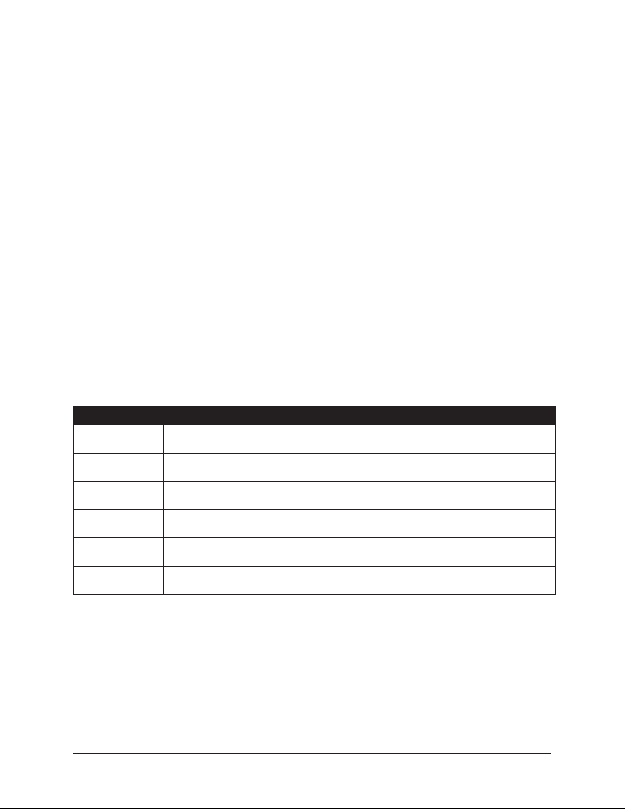
Two View Modes: Single View & Channel Strip View
Channel View has two fundamental modes of operation: Single view mode and Channel
Strip view mode. Single mode facilitates the viewing, editing, and management of
individual plug‑ins within a channel, while Channel Strip mode facilitates the concurrent
viewing, editing, and management of all serially stacked plug‑ins within a channel.
View Mode Elements
The screen elements and functions in Channel View depend on the active view mode,
and the current selections within the active mode. Some elements and functions are
common to both view modes. All elements are detailed later in this section.
Switching View Modes
To enter Channel Strip view, click the Channel Strip Button at the bottom of the Main
Column when in Channel View. The button is highlighted blue when Channel Strip view
is active. Click the button again, or click any Insert Button, to return to Single view.
Common Elements
Some elements that appear, and the functions that can be performed, are common to
both Single and Channel Strip view modes. The elements common to both views are the
Main Column, Channel I/O Gains, PLUG‑IN Tab, and the PRESET Tab.
The common elements are described briefly in the table below.
Element Description
Channel Name
Button
Insert Buttons
Channel Strip
Button
PLUG‑IN(S) Tab
Supporting Tabs
Channel I/O Gains
Displays the current channel’s NAME field. Click the button to create a custom name
for the channel.
Represent the channel’s eight available insert slots. Shows the name of currently
loaded channel plug‑ins (if any). Switches between the inserts for editing inserts.
Toggles the channel between Single view and Channel Strip view modes. Facilitates
the viewing and editing of multiple plug‑in interfaces concurrently.
Displays the plug‑in interface so sonic parameters can be edited. Depending on the
view mode (Single or Channel Strip), different supporting tabs are available.
In Single view, PRESETS and ASSIGN tabs are available for selecting presets and
plug‑ins. In Channel Strip view, the CHANNEL PRESETS tab is available.
Input/output gain faders and level meters are available for convenient gain staging.
These are the same controls available in Gains View.
UAD‑2 Live Rack Manual Chapter 4: Live Rack Application 81
Page 82

Channel View Options
PRESETS
Tab
ASSIGN
Tab
PLUG‑IN
Tab
Selected
Channel
(blue)
Power
Button
ZOOM
Slider
Channels
Bar
In Channel View, the View Options in the Main Column is identical in
both Single and Channel Strip view modes. The options in Channel
View are the Channel Name button, the Insert buttons, and the
Channel Strip button.
Channel Name Button
The Channel Name button is located directly beneath the View Menu
in the Main Column. It displays the name of the channel selected
in the Channel Bar. The Channel Name appears alongside the MADI
channel number.
When the Channel Name button is clicked, the button is highlighted
in blue, and the NAME field and LINK (UNLINK) button appears to
the right of the Main Column so the channel can be named or stereo
linked/unlined.
Note: The MADI channel number cannot be modified.
Channel Name Field
To change the channel name, click the
Channel Name button to display the NAME
field. Type a new value in the NAME
field, then type Return (or Enter) or click
anywhere outside the field.
Channel
Name
Button
Selected
Insert
(blue)
Insert
Buttons
Channel
Strip
Button
At right: Changing the channel name. To
see the NAME field and LINK (UNLINK)
button, click the Channel Name button.
Tip: The NAME field remains visible
when other Channel Select buttons in the Channel Bar are clicked so other
channels can be quickly renamed.
Channel Link/Unlink
To stereo link or unlink a channel(s) the channel name, click the Channel Name button
to display the LINK button (or UNLINK button, if the channels are already stereo linked).
Click the Link/Unlink button to change the link state. For specific details about link/
unlink behavior, see “Link/Unlink” on page 71.
Caution: Link/Unlink can cause significant audio changes and can only be
performed in EDIT mode.
UAD‑2 Live Rack Manual Chapter 4: Live Rack Application 82
Page 83

Insert Buttons
The Insert Buttons are located in the Main Column. Each Insert
Button represents one of the eight insert slots for available for UAD
plug‑in processing within a single channel.
Populated inserts contain the plug‑in name and empty inserts
contain the plus “+” symbol.
Note: In SAFE mode, all plus “+” symbols are hidden and plugins cannot be assigned to the channel.
Insert Button Behavior
Insert buttons can be controlled with the mouse or the keyboard, as
described below.
Click
Clicking an Insert button with the mouse selects the insert. The
insert is selected when its button is highlighted in blue.
If if the insert already contains a plug‑in when its button is clicked,
its interface is displayed in the PLUG‑IN tab so the plug‑in
parameters can be modified.
If the insert does not already contain a plug‑in (any button with the
plus “+” symbol), the ASSIGN tab is displayed so a plug‑in can be
loaded into the insert.
If Channel Strip view is active (if the CHANNEL STRIP button is highlighted blue), the
channel is switched to Single view and the buttons behave as described above.
Focus
In Single view, if an Insert button has focus (when the button is selected and its button
is highlighted in blue) and the Return or Enter key is typed, the PRESETS tab is selected
so plug‑in settings files can be navigated and loaded from disk.
In Channel Strip view, if the channel strip has focus (when the CHANNEL STRIP button
is highlighted in blue and the FOCUS outline is around the Insert and Channel Strip
buttons) and the Return or Enter key is typed, the PRESETS tab is selected so channel
strip settings files can be navigated and loaded from disk.
UAD‑2 Live Rack Manual Chapter 4: Live Rack Application 83
Page 84

Channel Signal Flow
Audio signals in a channel flow through the inserts serially from top to bottom. Therefore,
if more than one plug‑in is inserted in a channel, the location of a plug‑in within the
inserts can impact the sound of the channel.
Insert Reordering
Inserts can be reordered to change the location of a plug‑in within
the channel signal flow. For example, its possible to move an EQ
to be located before or after a compressor to change the processed
sound.
To reorder the inserts, drag any Insert Button up or down with the
mouse. Existing assignments are automatically reordered as needed to accommodate the
change. Inserts can be reordered in Single view and Channel Strip view.
Note: This operation can only be performed in EDIT mode.
Insert State Indications
The color of each button, as well as italic plug-in names, indicate
of the current state of each insert. The possible states are shown at
right and described below.
Selected (light blue) – The plug‑in is active and processing audio,
and the insert is selected for editing. The PULTEC EQP‑1A insert
button at right indicates this state.
Active (light gray) – The plug‑in is active and processing audio. The
TELETRONIX LA‑2A GRAY insert button at right indicates this state.
Inactive (dark blue) – The plug‑in has been disabled by the power
button in Channel View, and the plug‑in name is italicized, and the
plug‑in displays a Status Bar in the PLUG‑IN Tab. The EMT 250
insert button at right indicates this state.
Note: Disabling a plug-in via the power control within the plugin interface (versus the power button in Channel View) does not
change the background color nor italicize the name.
Disabled (red) – The plug‑in is disabled because there is not enough
UAD resources, it is unlicensed and the demo has expired, and/
or the UAD authorization needs updating. The plug‑in name is also italicized and the
plug‑in displays a Status Bar in the PLUG‑IN Tab. The MANLEY MASSIVE PASSIVE
insert button in the screenshot indicates this state.
Italic Name – The plug‑in is not processing audio because it is either inactive or
disabled.
Empty (+) – The insert is not populated with a plug‑in. Click the plus ”+” symbol to
assign a plug‑in into the slot.
Note: The plus “+” symbol on all Insert buttons is hidden in SAFE mode.
UAD‑2 Live Rack Manual Chapter 4: Live Rack Application 84
Page 85

Channel Strip Button
The Channel Strip button is used to enter Channel Strip view.
Channel Strip view combines all plug‑ins in a channel into a single
view for convenient editing and settings management.
Activating Channel Strip View
To enter Channel Strip view, click the CHANNEL STRIP button
at the bottom of the Main Column. To exit Channel Strip view
and enter Single view, click the CHANNEL STRIP button again to
change it to gray, or click any Insert button.
Remove Plug-In Shortcut
Plug‑ins can also be from inserts in using the shortcut on the Inserts
buttons. This operation cannot be performed in SAFE mode.
Tip: Plug-in removal operations in Inserts View can be much
quicker, especially when removing numerous plug-ins.
To use the shortcut:
1. Drag any insert button containing a plug‑in to the left to reveal the Remove
modifier icon
2. Click the Remove icon to delete the plug‑in from the insert.
To cancel the operation, click anywhere else in the Insert Buttons area (anywhere except
the Remove icon).
Channel I/O Gains
Input and output gain faders and signal level meters are displayed within all
screens in Channel View, between the Inserts Buttons and the Tab displays.
The Channel I/O Gains are used to adjust view and adjust input and output
levels for individual channels.
The channel I/O fader and meter functionality is exactly the same as in Gains
View, where the I/O gain controls are displayed concurrently for all channels.
For details about these controls, see “Gain Elements” on page 70.
UAD‑2 Live Rack Manual Chapter 4: Live Rack Application 85
Page 86

PLUG-IN Tab
The PLUG‑IN Tab is where the UAD plug‑in interface is displayed and plug‑in
parameters are edited. In Single view, the PLUG‑IN Tab displays the plug‑in interface
of the currently selected Insert Button in the Main Column. In Channel Strip view, the
interfaces of all plug‑in in the channel are displayed concurrently.
Channel
Name
Button
Selected
Insert
(blue)
Insert
Buttons
Channel
Strip
Button
Selected
Channel
(blue)
PLUG‑IN
Tab
PRESETS
Tab
ASSIGN
Tab
Power
Button
ZOOM
Slider
Channels
Bar
Channel I/O Gains Plug‑In Interface of Selected Insert(s)
Channel View elements when the PLUG-IN tab is active
General Use
For general information about how to use the UAD plug‑in interface (such as how to
adjust controls) see “Chapter 6: Using UAD Plug‑Ins” beginning on page 133.
Specific Controls
For information about the specific features and controls available within each individual
UAD plug‑in, see the UAD Plug‑Ins Manual.
UAD‑2 Live Rack Manual Chapter 4: Live Rack Application 86
Page 87

Channel Strip View
If Channel Strip view is active, the interfaces all inserted plug‑ins in the channel are
displayed in the PLUG‑INS tab concurrently. In Channel Strip view, the Tab name is
PLUG‑INS (plural) to reflect that multiple plug‑in interfaces are displayed in Channel
Strip view concurrently.
Channel Strip Button
The Channel Strip button is used to enter Channel Strip view.
Channel Strip view combines all plug‑ins in a channel into a single
view for convenient editing and settings management.
Activating Channel Strip View
To enter Channel Strip view, click the CHANNEL STRIP button
at the bottom of the Main Column. To exit Channel Strip view
and enter Single view, click the CHANNEL STRIP button again to
change it to gray, or click any Insert button.
Navigation Scroll
If the interfaces of all plug‑ins in the channel cannot be contained within the available
vertical screen space, vertical and/or horizontal scroll bars appear in the PLUG‑INS tab
to enable the viewing of all interfaces in the channel strip.
Hidden Functions
In Channel Strip view, the ZOOM slider and plug‑in DEACTIVATE button are hidden and
cannot be modified.
Channel Strip Variances
Channel Strip view is active when the CHANNEL STRIP button is highlighted in blue.
Additionally, the following functions are changed to accommodate Channel Strip view:
• All Insert Buttons are grouped and highlighted in blue
• The plug‑in ZOOM slider is hidden
• The plug‑in DISABLE button is hidden
• PRESETS and ASSIGN tabs are hidden
• The title of the PLUG‑IN tab changes to PLUG‑INS
• If the interfaces of all plug‑ins in the channel cannot be contained within the
available vertical screen space, vertical scroll bars appear in the PLUG‑INS tab to
enable the viewing of all interfaces in the channel strip.
UAD‑2 Live Rack Manual Chapter 4: Live Rack Application 87
Page 88

Status Bar
The Status Bar is a horizontal strip below the plug‑in interface that appears when there is
an exception to the usual operational state of the plug‑in. The status bars are described
below.
The Status Bar appears beneath the plug-in interface to indicate operating exceptions
• No Status Bar – The plug‑in is authorized, active, and processing audio.
• DEMO (days remaining) – The plug‑in is active and processing audio, but it is
operating in demonstration mode. The number of days remaining in the demo
period is displayed in the Status Bar. Demos can be started for each individual
plug‑ins in View Menu>Settings>PLUG‑INS. For related information, see “Demo
Mode” on page 143.
• POWERED OFF – The plug‑in has been disabled by the Power Button in Channel
View or Inserts View.
Note: Disabling a plug-in via the power control within the plug-in interface (versus
the Power button in Channel View) does not display this Status Bar.
• DISABLED – The plug‑in is disabled because there is not enough UAD resources,
it is unlicensed and the demo has expired, and/or the UAD authorization needs
updating.
UAD‑2 Live Rack Manual Chapter 4: Live Rack Application 88
Page 89

Power Button
The Power button deactivates the selected plug‑in and reduces UAD resource
loads. When a plug‑in is deactivated with this button, the button is red and
POWERED OFF appears in the Status Bar under the plug‑in interface.
The Power button is located between the Tabs and the ZOOM slider in Channel
View when the PLUG‑IN Tab is active. To disable the currently selected plug‑in,
click the green Power button. To re‑enable the plug‑in click, the Power button
again.
Zoom Slider
The ZOOM slider increases the size of the currently selected plug‑in interface. Zooming
enlarges all controls in the interface for enhanced visual feedback and controls
manipulation.
The Zoom setting is unique for each individual UAD plug‑in. The zoom setting for each
plug‑in is global; the setting is used throughout Channel View wherever the interface
appears.
Note: Zoom is unavailable in Channel Strip view.
Zoom slider
UAD‑2 Live Rack Manual Chapter 4: Live Rack Application 89
Page 90

PRESETS Tab
The PRESETS tab is where UAD plug‑in settings are managed after a plug‑in is assigned
to an Insert. Preset management tasks are performed on the currently selected Insert.
The PRESETS tab displays 3 columns with the currently selected plug-in’s presets, sub-
folders (if applicable), and the FILE menu for creating user-defined presets and folders.
Presets Defined
A preset is a complete collection of settings for an individual plug‑in that is
saved as a disk file so the settings can be subsequently recalled. Presets are
typically used to save and recall favorite plug‑in settings. Thousands of factory
presets are installed with the software, or they can be user‑created.
Note: Preset files do not contain a channel’s I/O gain values. However, I/O gain
values are stored within Snapshots (complete Live Rack configuration files).
Preset files have the “.vst” suffix (file suffixes are only visible in the macOS Finder when
the “Show all filename extensions” option is checked in the macOS Finder’s Preferences
window).
UAD‑2 Live Rack Manual Chapter 4: Live Rack Application 90
Page 91

Factory Presets
Factory presets are plug‑in settings created by the plug‑in developers for typical
use case scenarios. All UAD plug‑ins developed by Universal Audio include a batch
of factory presets. They can be used as‑is, or modified as desired.
All factory presets are read‑only; they cannot be overwritten, renamed, deleted, or
moved. However, factory presets can be saved under a different name or in a different
file location. Factory presets are indicated by a lock icon at the left of a preset icon.
Note: Not all Direct Developer (3rd-party) plug-ins include factory presets.
Presets Folder Location
All factory and user preset files are stored at the following location within the macOS file
system:
• Macintosh HD/Library/Application Support/Universal Audio/Presets
Plug-In’s Preset Folder
Inside the presets folder are folders named with the title of each UAD plug‑in.
Each of these folders contain all factory and user presets for that particular
plug‑in. This is the plug-in’s preset folder. The contents of this folder is
displayed in the PRESETS column when the PRESETS tab is selected.
Note: User presets can only be saved to the plug-in’s preset folder. Therefore,
the plug-in’s preset folder is the starting point, and highest level, for file system
navigation within the PRESETS tab.
Preset Sub-Folders
Each plug‑in’s preset folder can contain a maximum of one nested sub‑folder for
additional preset organization capability. This additional folder is the preset sub-folder.
The contents of this sub‑folder (if any) is displayed in the SUB‑FOLDER column when a
folder in the PRESETS tab is selected.
Channel Strip Defined
A Channel Strip is a complete collection of plug‑ins within a single channel,
and all parameter settings within those plug‑ins, that is saved as a disk file
so the channel strip can be subsequently recalled into the same or a different
channel. All Channel Strips are user‑created.
Note: Channel Strip files do not contain a channel’s I/O gain values. However, I/O
gain values are stored within Snapshots (complete Live Rack configuration files).
Channel strip files have the “.uadchannel” suffix. File suffixes are only visible in the
macOS Finder when the “Show all filename extensions” option is checked in the macOS
Finder’s Preferences window.
UAD‑2 Live Rack Manual Chapter 4: Live Rack Application 91
Page 92

Channel Strip Folder Location
All Channel Strip files are stored at the following location within the macOS file system:
• Macintosh HD/Library/Application Support/Universal Audio/Presets/Channel Strip
Channel Strip Sub-Folders
The Channel Strip folder can contain a maximum of one nested sub‑folder for
additional channel strip organization capability. This additional folder is the
Channel Strip sub-folder. The contents of this sub‑folder (if any) is displayed
in the SUB‑FOLDER column when a folder in the CHANNEL PRESETS tab is
selected in Channel Strip view.
Note: Channel Strip presets can only be saved to the Channel Strip folder.
Therefore, the Channel Strip folder is the starting point, and highest level, for file
system navigation within the CHANNEL PRESETS tab.
PRESETS Tab Columns
The PRESETS tab contains three columns: FILE, PRESETS, and SUB‑FOLDERS. These
columns are used to manage and navigate the preset files.
Note: In Channel Strip view mode, the PRESETS tab is named CHANNEL
PRESETS.
FILE Column
The FILE column in the PLUG‑IN tab contains buttons used to
name, save, and perform other file management tasks. Click the
button to perform the operation on the currently selected preset or
sub‑folder.
SAVE
Saves the current modified preset file in place. The preset file must
already exist or the button is unavailable (gray). Use the SAVE AS
button to perform the initial save operation.
SAVE AS
Creates a new preset file to disk with the plug‑in’s current settings.
Opens the SAVE PRESET AS file dialog overlay so a new preset
name can be entered and saved to a location within the plug‑in’s
preset folder. A sub‑folder can be created within the SAVE PRESET
AS dialog.
RENAME
Presents the RENAME PRESET dialog overlay so the currently selected preset can be
renamed.
UAD‑2 Live Rack Manual Chapter 4: Live Rack Application 92
Page 93
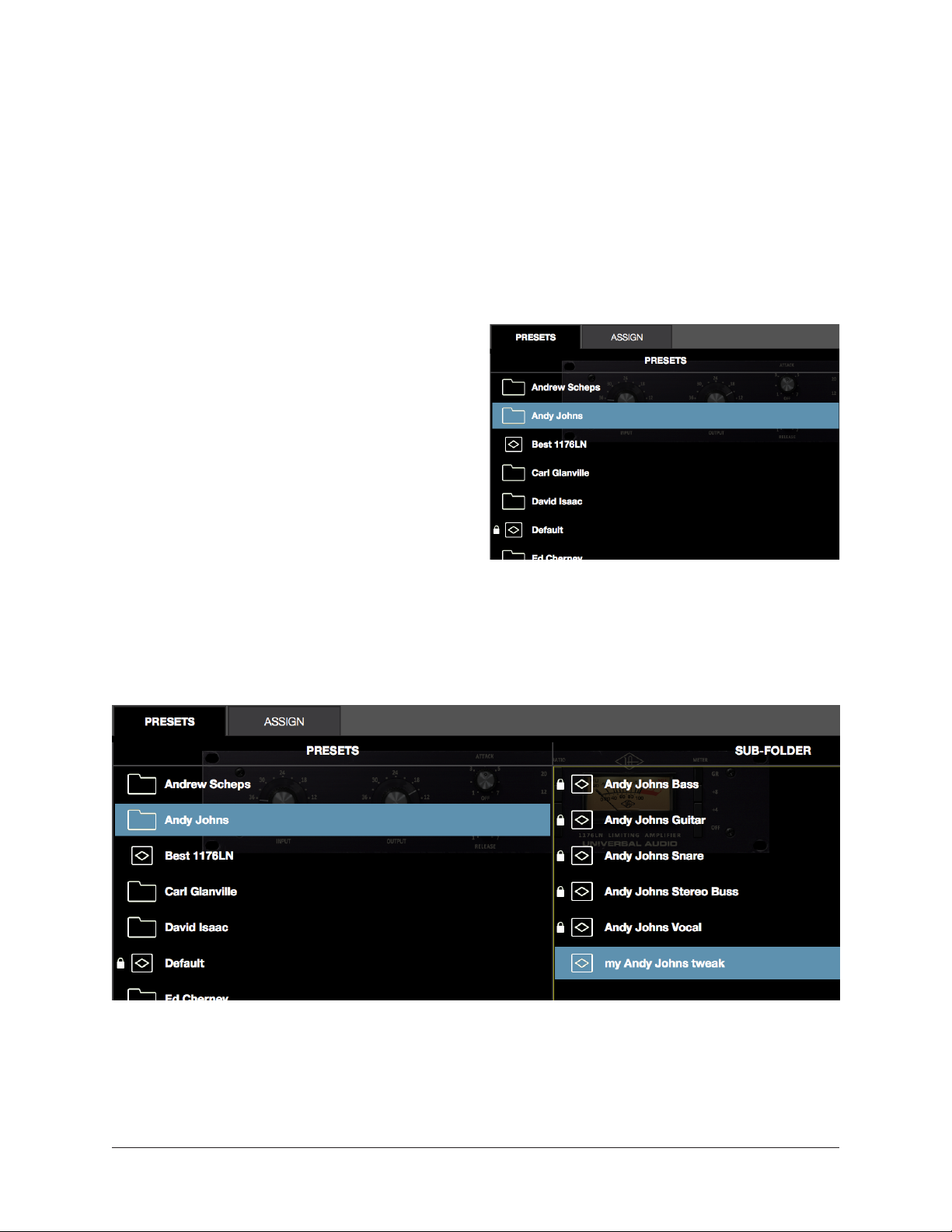
DELETE
Presents the DELETE PRESET dialog overlay so the currently selected item can be
permanently deleted.
Note: The Delete operation cannot be undone.
MOVE
Presents the MOVE dialog overlay so the currently selected item can be moved to another
location within the plug‑in’s preset folder.
PRESETS Column
When the PRESETS tab is selected, the
PRESETS column is visible and all items
within the plug‑in’s preset folder are
displayed. Actions in the FILE menu can
be performed on items selected in the
PRESETS column.
Click any preset in the PRESETS column to
instantly load it, or click a sub‑folder (if any)
to display presets within the sub‑folder in
the SUB‑FOLDER column.
SUB-FOLDER Column
If the PRESETS column contains one or more folders, selecting the folder will display
items in the sub‑folder. Actions in the FILE menu can be performed on any item selected
in the SUB‑FOLDER column.
The SUB-FOLDER column is displayed when a folder in the PRESETS column is selected
UAD‑2 Live Rack Manual Chapter 4: Live Rack Application 93
Page 94
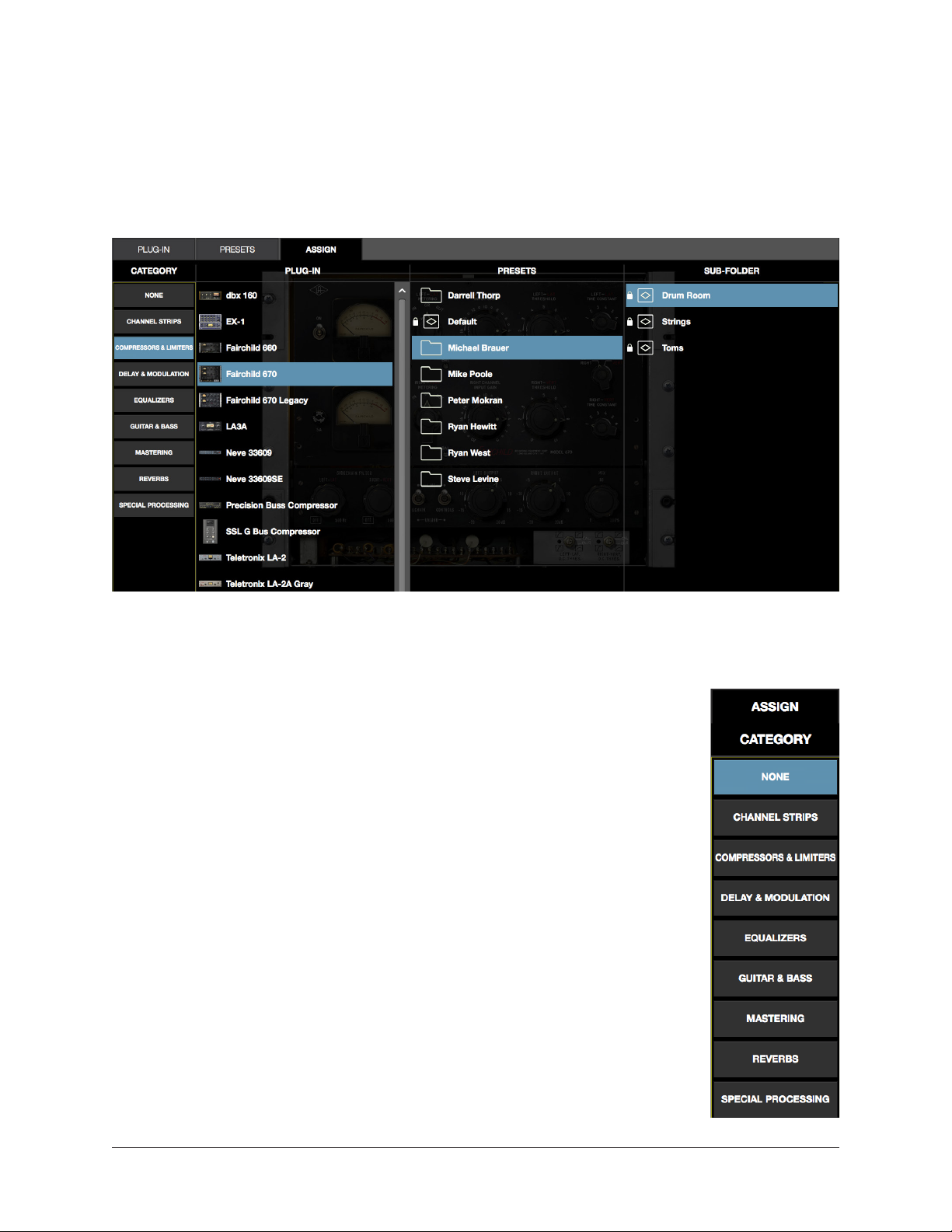
ASSIGN Tab
The ASSIGN tab is used to assign (load) plug‑ins into empty inserts and reassign
(replace) existing plug‑ins that are already assigned in a channel insert. Actions in the
ASSIGN tab are performed on the currently selected insert.
Note: The ASSIGN tab is unavailable in Channel Strip view.
The ASSIGN tab showing typical selections within the Category menu
CATEGORY Buttons
UAD plug‑ins that have similar processing functionality are grouped
within categories. The CATEGORY buttons in the ASSIGN tab represent
these plug‑in categories.
Note: Some plug-ins are in multiple categories (when applicable).
Plug‑ins are assigned and reassigned by selecting a category button,
then choosing a plug‑in or preset from the PLUG‑IN, PRESETS, or SUB‑
FOLDER columns that appear when a category is selected.
Making selections
Click a Category button to “drill down” through available selections.
Single‑click a plug‑in to display the PRESETS column (and SUB‑
FOLDER column, if any) columns. Double‑click a plug‑in to load it
with its default settings. For detailed instructions, see “How To Assign
Inserts” on page 95.
PRESETS & SUB-FOLDER Columns
These columns function identically to the same columns in the
PRESETS tab. For details, see “PRESETS Tab Columns” on page 92.
UAD‑2 Live Rack Manual Chapter 4: Live Rack Application 94
Page 95

Plug-In Categories
Available plug‑in categories are listed in the table below.
Note: Some plug-ins are in multiple categories (when applicable).
CATEGORY CONTENTS
NONE
DELAY Delay and echo plug‑ins
DYNAMICS Compressor and limiter plug‑ins
EQUALIZATION EQ plug‑ins
GUITAR & BASS Guitar and bass amplifiers, pedals, and tuner plug‑ins
HARMONIC & TAPE Filter, saturation, distortion, and analog tape plug‑ins
MASTERING Mastering plug‑ins
MICROPHONE Plug‑ins for Townsend Labs Sphere L22 Microphone Modeling System
MODULATION Chorus, modulation, phaser, and doubler plug‑ins
PREAMP & CHANNEL STRIP Preamps and plug‑ins featuring multiple modules
REVERB & ROOM Digital reverb, analog reverb, and room emulation plug‑ins
SPECIAL PROCESSING Tape machines, enhancers, transient designers, phase tools
Indicates that no plug‑in is assigned. If a plug‑in is already assigned,
the button can be used to unload the plug‑in.
How To Assign Inserts
Follow these instructions to assign (load), reassign (change), and de‑assign (remove)
plug‑ins from any insert in Channel View.
Note: These operations can only be performed in EDIT mode.
Assign Insert
1. Single‑click any empty insert button in any View screen to switch into Channel
view and select the insert. The ASSIGN tab and the CATEGORY buttons are
displayed, with NONE as the currently selected category.
2. Single‑click any CATEGORY button to select it. The plug‑ins within the category
are displayed in the PLUG‑IN column. Use the vertical scroll bar to view all the
plug‑ins if necessary.
3. Single‑click any plug‑in the PLUG‑IN column to assign it to the insert. The plug‑in
is loaded with its default preset, it begins processing audio on the channel, and
the PRESETS column (and SUB‑FOLDER column, if any) are displayed.
4. If desired, single‑click any preset in the PRESETS or SUB‑FOLDER columns to
load a different preset. Use the vertical scroll bar to view all the presets and/or
sub‑folders if necessary.
Done. Exit assign mode by pressing enter or clicking a different element. Click the
PLUG‑IN tab to view the plug‑in’s interface and edit its parameters.
UAD‑2 Live Rack Manual Chapter 4: Live Rack Application 95
Page 96

Reassign Insert
1. Single‑click any populated insert button in any View screen to switch into Channel
view and select the insert. The PLUG‑IN tab is selected and the plug‑in interface
is displayed.
2. Single‑click the ASSIGN tab. The CATEGORY button of the current plug‑in is
selected, along with the PRESET column (and SUB‑FOLDER column, if any).
3. Single‑click any CATEGORY button to select it. The plug‑ins within the category
are displayed in the PLUG‑IN column. Use the vertical scroll bar to view all the
plug‑ins if necessary.
4. Single‑click any plug‑in the PLUG‑IN column to assign it to the insert. The old
plug‑in is replaced by the new plug‑in with its default preset, and the PRESETS
column (and SUB‑FOLDER column, if any) are displayed.
5. If desired, single‑click any preset in the PRESETS column (or SUB‑FOLDER
column, if any) to load the preset. Use the vertical scroll bar to view all the
presets and/or sub‑folders if necessary.
Done. Exit assign mode by pressing enter or clicking a different element. Click the
PLUG‑IN tab to view the plug‑in’s interface and edit parameters.
De-assign Insert
Tip: Plug-in de-assignment in Inserts View via the Remove function can be much
quicker, especially when removing numerous plug-ins.
1. Single‑click any populated insert button in any View screen to switch into Channel
view and select the insert. The PLUG‑IN tab is selected and the plug‑in interface
is displayed.
2. Single‑click the ASSIGN tab. The CATEGORY button of the current plug‑in is
selected, along with the PRESET column (and SUB‑FOLDER column, if any).
3. Single‑click the NONE category button. The plug‑in is removed from the insert
and UAD resources used by the plug‑in are released.
Done. Exit assign mode by pressing enter or clicking a different element.
Tip: Plug-ins can also be de-assigned using the drag-to-left
shortcut on the insert buttons (shown at right). For details, see
page 85.
UAD‑2 Live Rack Manual Chapter 4: Live Rack Application 96
Page 97

Snapshots View
A Snapshot is complete Live Rack configuration file used for total session recall.
Snapshots contain all parameter values within the Live Rack application.
Snapshots View is a dedicated file management screen for saving, modifying, recalling,
importing, and exporting Snapshot files. Snapshots View has the four sections described
in the table below.
SNAPSHOTS SECTION DESCRIPTION
Snapshot Options
Folders & Snapshots Columns Displays a list of user‑defined folders and Snapshots in two columns.
Recall Panel
Universe View
The options the Main Column contain the various Snapshot file and
folder management functions.
Displays the currently loaded Snapshot, the currently primed (selected)
snapshot, and the Recall button to load the primed Snapshot.
Displays a high‑level view of the currently loaded Snapshot. Colored
boxes indicate the presence and status of all plug‑ins in all channels.
Snapshot Defined
A snapshot is a complete collection of all settings for the entire active Live
Rack configuration. “All settings” are all parameter values in all Views,
including all plug‑in assignments in all channels, the current settings and state
(active, disabled, etc) of all assigned plug‑ins, and I/O Gain and Delay Group
settings for all channels. All Snapshots are user‑created.
Snapshots are saved as a disk file so the complete session can be subsequently recalled
and/or transferred between systems and operators. Snapshots can be loaded from within
Snapshots View, via MIDI, or from within Soundcraft Vi consoles via Ethernet using the Vi
CUE functions.
Snapshots files have the “.uadmix” suffix. File suffixes are only visible in the macOS
Finder when the “Show all filename extensions” option is checked in the macOS Finder’s
Preferences window.
Snapshots Folder Location
All Snapshot files are stored at the following location within the macOS file
system:
• Macintosh HD/Users/[account name]/Documents/Universal Audio/Snapshots
UAD‑2 Live Rack Manual Chapter 4: Live Rack Application 97
Page 98

Snapshot Versus System Contents
The table details the information that is stored in a Snapshot file and the differences
between a Snapshot and what is stored within the system.
Settings Stored In Snapshots
(changed when Snapshot is recalled)
Snapshot name
Snapshot MIDI Program Change number
Snapshot BPM (Tempo)
Session channel‑count (16, 32, 48, or 64)
Plug‑ins and settings per‑channel (includes all
parameters and DSP power state)
Input and Output Gain settings per‑channel
Stereo Link state per‑channel
Delay Group setting per‑channel
Settings Stored In System
(persist when Snapshot is recalled)
Clock Source setting
Sample Rate setting
MADI process order setting
Device order setting
Channel Name
All screen preferences (as set in the Hardware tab
within Settings View)
All MIDI preferences (as set in the MIDI tab within
Settings View)
All Plug‑Ins preferences (as set in the PLUG‑INS
tab within Settings View)
Snapshot Key Commands
At any time (not just in Snapshots view), two key commands can be executed for
saving the current Snapshot in place (SAVE), or saving the current s\Snapshot as a new
Snapshot (SAVE AS).
Key Command Name Key Command Description
Save Snapshot COMMAND+S Saves the current snapshot in place
Save Snapshot As... COMMAND+SHIFT+S Saves the current snapshot as a new snapshot with
a new name and/or location
UAD‑2 Live Rack Manual Chapter 4: Live Rack Application 98
Page 99

Recalling Snapshots
Recalling a Snapshot can cause destructive actions such as building and/or reordering of
plug‑in chains. Therefore, when a Snapshot is recalled, channels may be muted to avoid
audio artifacts.
If a Snapshot is loaded that has the same plug‑in configuration as the currently loaded
Snapshot, the plug‑ins are not rebuilt and only parameter values are changed, enabling a
(mostly) artifact‑free Snapshot recall workflow.
Caution: When SAFE mode is active, Snapshots can still be recalled, which can
potentially overwrite current plug-in assignments and cause audio artifacts during
live a performance.
Base Snapshot Workflow
Recalling Snapshots can be potentially destructive in that entire plug‑ins and plug‑in
channel strips can be torn down and re‑built, potentially causing audio artifacts and/or
silence for the duration of the Snapshot loading process.
For this reason, it is highly recommended that a “Base Snapshot” be prepared that
contains all of the plug‑ins required to get through a show/performance and only create
snapshots that are saved as variants of the base snapshot.
Important: Recalling Snapshots created using the method below will result in
parameter values being changed without significant glitches or muting.
To create Snapshots variants from a base Snapshot:
1. Create the base Snapshot by loading as many plug‑ins as needed for the show/
performance/session.
2. Navigate to Snapshots View.
3. Click SAVE AS to save and name the base Snapshot file.
4. When a change is needed (for example, for a change in the song or a different
song that needs new settings), click SAVE AS again to create and name the
variant Snapshot.
5. Make the parameter changes needed in the variant Snapshot and press SAVE.
This locks the parameter change deltas into the variant Snapshot file.
6. Repeat steps 4 and 5 for all the variant snapshots that are needed.
The base and variant Snapshots can now be switched with minimal artifacts.
UAD‑2 Live Rack Manual Chapter 4: Live Rack Application 99
Page 100
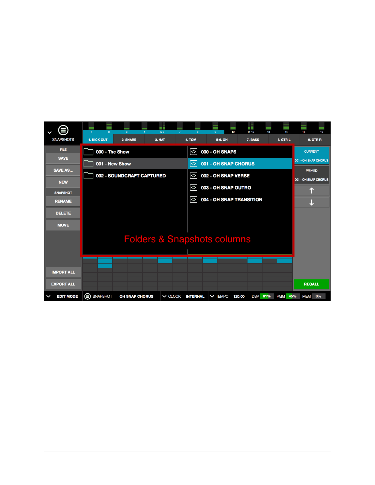
File Columns
The upper middle section of the Snapshots View screen shows two columns that display
the Snapshot folders and the Snapshot files contained within the folders. Similar to how
plug‑in and channel strip presets are managed, these folders and files are used to load
and manipulate the files in various ways.
However, unlike plug‑in and channel strip presets, there are some differences between
how Snapshots are loaded and moved. These differences were designed for safety
reasons (for example, to prevent accidental triggers during a live show).
Snapshots View columns display the Snapshot folders (left) and Snapshot files (right)
UAD‑2 Live Rack Manual Chapter 4: Live Rack Application 100
 Loading...