

Page 1

UAD-1 P
U
SER
ERSION
V
Manual Version 040113
M
3.4
ANUAL
OWERED
P
LUG
-I
NS
330 Encinal Street
Santa Cruz, CA 95060-2101
voice: 831-466-3737
fax: 831-466-3775
Email Inquiries
info@uaudio.com
World Wide Web
www.uaudio.com
www.poweredplugins.com
Page 2

Notice
This manual provides general information, preparation for use, installation
and operating instructions for the Universal Audio Powered Plug-Ins.
The information contained in this manual is subject to change without
notice. Universal Audio, Inc. makes no warranties of any kind with regard to
this manual, including, but not limited to, the implied warranties of
merchantability and fitness for a particular purpose. Universal Audio, Inc.
shall not be liable for errors contained herein or direct, indirect, special,
incidental, or consequential damages in connection with the furnishing,
performance, or use of this material.
Copyright
© 2004 Universal Audio, Inc. All rights reserved.
This manual and any associated software, artwork, product designs, and
design concepts are subject to copyright protection. No part of this
document may be reproduced, in any form, without prior written permission
of Universal Audio, Inc. Your rights to the software are governed by the
accompanying software license agreement.
Trademarks
UAD-1, Powered Plug-Ins, LA-2A, 1176, EX-1, DM-1, RS-1, CS-1
Channel Strip, and the Universal Audio, Inc. logo are trademarks of
Universal Audio, Inc. RealVerb, RealVerb Pro, the Kind of Loud logo, and
the Kind of Loud In Here mark are trademarks of Kind of Loud
Technologies, LLC. Other company and product names mentioned herein
are trademarks of their respective owners.
Universal Audio, Inc. End-User License Agreement
IMPORTANT - PLEASE READ THIS LICENSE AGREEMENT
CAREFULLY BEFORE OPENING THE ACCOMPANYING
PACKAGE. This Universal Audio, Inc. End-User License Agreement
(“Agreement”) is a legal agreement between you (either an individual or a
single entity), as an end-user, and Universal Audio, Inc (“Universal Audio”)
for the software accompanying this Agreement, which includes computer
software and any bug fixes subsequently delivered and associated media,
printed materials and “online” or electronic documentation (collectively, the
“Software”). The Software is licensed, not sold, by Universal Audio to the
original end user for use only on the terms set forth here. By exercising your
rights to install, copy and use the Software, you agree to be bound by these
terms. If you do not agree to these terms, you may not install, copy or use the
Software.
1 Limited Use License . Universal Audio, as Licensor, grants you, as Licensee,
a non-exclusive license to use the Software with a single computer unit at a
single location.
2 Title . The Software is owned by Universal Audio or its suppliers and is
protected by copyright laws and international treaty provisions, as well as
other intellectual property laws and treaties. Universal Audio retains title to
and ownership of the Software and all copies thereof in any form. Universal
Audio retains all rights in the Software not specifically granted to the
Licensee. Nothing in this Agreement constitutes a waiver of Universal
Audio’s rights under United States copyright law or any other law.
3 Permitted Use and Restrictions . You may install the Software into the
memory of a single computer, but may not electronically transfer the
Software from one computer to another, or operate it in a time-sharing or
service-bureau operation. You may make one copy of the Software for
backup purposes only (and replacement backup copies in the event of loss of
or damage to a backup copy), provided you include all copyright notices
contained on the original media on the backup copy. You may not modify,
translate, adapt, reverse engineer, decompile, create other works from, or
disassemble the Software or any portions thereof. Similarly, you may not
copy, modify, adapt, transfer, or create other works based upon the printed
materials and “online” or electronic documentation accompanying or
published for use with the Software (the “Documentation”).
4 Transfer . You may not export, transfer, convey, rent, sublicense, or
otherwise distribute the Software or any rights therein to any person or
entity.
5 Limited Warranty . Universal Audio grants solely to you a limited warranty
for a period of ninety (90) days from the original purchase date that the
media on which the software is distributed shall be substantially free from
material defects. Your exclusive remedy, at Universal Audio’s option, is to
return and have replaced the inaccurate media containing the software
programs or receive a refund of the price paid within the warranty period.
UNIVERSAL AUDIO DOES NOT WARRANT THAT THE
SOFTWARE WILL MEET YOUR REQUIREMENTS OR THAT ITS
OPERATION WILL BE UNINTERRUPTED OR ERROR-FREE.
EXCEPT AS SPECIFIED HEREIN, UNIVERSAL AUDIO MAKES NO
WARRANTIES OR REPRESENTATIONS, EXPRESS OR IMPLIED,
REGARDING THE SOFTWARE, DOCUMENTATION, OR MEDIA,
AND HEREBY EXPRESSLY DISCLAIMS THE WARRANTIES OF
MERCHANTABILITY, FITNESS FOR A PARTICULAR PURPOSE,
AND NONINFRINGEMENT OF THIRD PARTY RIGHTS.
FURTHERMORE, UNIVERSAL AUDIO DOES NOT WARRANT OR
MAKE ANY REPRESENTATIONS REGARDING THE USE OR THE
RESULTS OF THE USE OF THE SOFTWARE OR
DOCUMENTATION IN TERMS OF THEIR CORRECTNESS,
ACCURACY, RELIABILITY, OR OTHERWISE. NO ORAL OR
WRITTEN INFORMATION OR ADVICE GIVEN BY UNIVERSAL
AUDIO OR A UNIVERSAL AUDIO-AUTHORIZED
REPRESENTATIVE SHALL CREATE A WARRANTY OR IN ANY
WAY INCREASE THE SCOPE OF THIS WARRANTY. EXCEPT AS
SPECIFIED HEREIN, SHOULD THE SOFTWARE PROVE
DEFECTIVE, YOU (AND NOT UNIVERSAL AUDIO OR A
UNIVERSAL AUDIO-AUTHORIZED REPRESENTATIVE) ASSUME
THE ENTIRE COST OF ALL NECESSARY SERVICING, REPAIR, OR
CORRECTION. SOME STATES DO NOT ALLOW THE
EXCLUSION OF IMPLIED WARRANTIES, SO THE ABOVE
EXCLUSION MAY NOT APPLY TO YOU.
6 Limitation of Liability . UNIVERSAL AUDIO SHALL HAVE NO
LIABILITY TO YOU OR ANY THIRD PARTY, WHETHER IN
CONTRACT, TORT, NEGLIGENCE OR PRODUCTS LIABILITY,
FOR ANY CLAIM, LOSS, OR DAMAGE, INCLUDING BUT NOT
LIMITED TO LOST PROFITS, LOSS OF USE, BUSINESS
INTERRUPTION, LOST DATA, OR LOST FILES, OR FOR ANY
INDIRECT, SPECIAL, INCIDENTAL OR CONSEQUENTIAL
DAMAGES OF ANY KIND OR NATURE WHATSOEVER ARISING
OUT OF OR IN CONNECTION WITH THE USE OF OR INABILITY
TO USE THE SOFTWARE OR DOCUMENTATION, OR THE
PERFORMANCE OR OPERATION OF THE SOFTWARE, EVEN IF
UNIVERSAL AUDIO HAS BEEN ADVISED OF THE POSSIBILITY
OF SUCH DAMAGES. SOME STATES DO NOT ALLOW THE
EXCLUSION OR LIMITATION OF INCIDENTAL OR
CONSEQUENTIAL DAMAGES, SO THE ABOVE EXCLUSION OR
LIMITATION MAY NOT APPLY TO YOU. IN NO EVENT SHALL
UNIVERSAL AUDIO’S TOTAL LIABILITY TO YOU FOR ALL
DAMAGES, LOSSES, AND CAUSES OF ACTION WHETHER IN
CONTRACT, TORT (INCLUDING NEGLIGENCE) OR
OTHERWISE EXCEED THE AMOUNT PAID BY YOU FOR THE
SOFTWARE.
7 Term . This Agreement is effective until terminated. You may terminate the
license without recompense at any time by returning the Software and all
Documentation and any copies thereof (whether or not the copying was
authorized hereunder) to Universal Audio and by removing the Software
from the memory of any computer into which the Software has been
transferred by you or with your permission. In addition to any other rights
of Universal Audio, this license may be terminated by Universal Audio
immediately and without notice in the event you fail to comply with any
term or condition hereof. Upon termination by Universal Audio, you will
return to Universal Audio, at your expense, the Software and all
Documentation and any copies thereof (whether or not the copying was
authorized hereunder).
8 United States Government Rights . The Software and Documentation are
provided with RESTRICTED RIGHTS. Use, duplication, or disclosure by
the Government is subject to restrictions as set forth in subparagraph
(c)(1)(ii) of the Rights in Technical Data and Computer Software clause at
DFARS 252.227-7013 or subparagraphs (c)(1) and (2) of the Commercial
Computer Software-Restricted Rights at 48 CFR 52.227-19, as applicable.
Manufacturer is Universal Audio, Inc./ Postal Box 3818/Santa Cruz,
CA/95063-3818.
9 Miscellaneous . This Agreement shall be governed by and construed in
accordance with the laws of the United States and the State of California, as
applied to agreements entered into and to be performed entirely within
California between California residents. If for any reason a court of
competent jurisdiction finds any provision of this License or portion thereof
to be unenforceable, that provision of the License shall be enforced to the
maximum extent permissible so as to effect the intent of the parties, and the
remainder of this License shall continue in full force and effect. This
Agreement constitutes the entire agreement between the parties with respect
to the use of the Software and Documentation, and supersedes all prior or
contemporaneous understandings or agreements, written or oral, regarding
such subject matter. No amendment to or modification of this License will
be binding unless in writing and signed by a duly authorized representative
of Universal Audio.
Should you have any questions concerning this Agreement, please contact
Universal Audio at Postal Box 3818, Santa Cruz, CA 95063-3818 USA,
+1 (831) 466-3737 voice, +1 (831) 466-3775 fax, www.uaudio.com web.
Page 3

TABLE OF CONTENTS
Chapter 1. Introduction . . . . . . . . . . . . . . . . . . . . . . . . . . . . . . . . . . . . . . . . .
Welcome
Features
System Requirements
Manual Conventions
. . . . . . . . . . . . . . . . . . . . . . . . . . . . . . . . . . . . . . . . . . . . . . . . . . . . . . . . . . . . . . . . . . . . 11
. . . . . . . . . . . . . . . . . . . . . . . . . . . . . . . . . . . . . . . . . . . . . . . . . . . . . . . . . . . . . . . . . . . . . 12
. . . . . . . . . . . . . . . . . . . . . . . . . . . . . . . . . . . . . . . . . . . . . . . . . . . . . . . . . . . 17
. . . . . . . . . . . . . . . . . . . . . . . . . . . . . . . . . . . . . . . . . . . . . . . . . . . . . . . . . . . 18
Chapter 2. Installation . . . . . . . . . . . . . . . . . . . . . . . . . . . . . . . . . . . . . . . . . .
Refer to the QuickStart Guides
Install Software First
. . . . . . . . . . . . . . . . . . . . . . . . . . . . . . . . . . . . . . . . . . . . . . . . . . . . . . . . . . . 19
Installing the UAD-1 Hardware
. . . . . . . . . . . . . . . . . . . . . . . . . . . . . . . . . . . . . . . . . . . . . . . . . . . 19
. . . . . . . . . . . . . . . . . . . . . . . . . . . . . . . . . . . . . . . . . . . . . . . . . . 20
Chapter 3. Using UAD-1 Powered Plug-Ins . . . . . . . . . . . . . . . . . . . . . . . . . . .
Overview
Launching a UAD-1 Powered Plug-In
UAD-1 DSP Performance Meter Application
Accessing Meter Functions
. . . . . . . . . . . . . . . . . . . . . . . . . . . . . . . . . . . . . . . . . . . . . . . . . . . . . . . . . . . . . . . . . . . . 21
. . . . . . . . . . . . . . . . . . . . . . . . . . . . . . . . . . . . . . . . . . . . . 24
. . . . . . . . . . . . . . . . . . . . . . . . . . . . . . . . . . . . . . . . 25
. . . . . . . . . . . . . . . . . . . . . . . . . . . . . . . . . . . . . . . . . . . . . . . . . . . . . . 26
11
19
21
Using the Meter
. . . . . . . . . . . . . . . . . . . . . . . . . . . . . . . . . . . . . . . . . . . . . . . . . . . . . . . . . . . . . . . 27
UAD-1 System Information Window
UAD-1 Configuration Window
Delay Compensation
. . . . . . . . . . . . . . . . . . . . . . . . . . . . . . . . . . . . . . . . . . . . . . . . . . . . . . . . . . . 39
UAD Delay Compensator plugin
DelayComp Examples
. . . . . . . . . . . . . . . . . . . . . . . . . . . . . . . . . . . . . . . . . . . . . . . . . . . . . . . . . . 42
Compensating for Pultec EQ
UAD Track Advance
TrackAdv Examples
Live Processing
DSP Usage
. . . . . . . . . . . . . . . . . . . . . . . . . . . . . . . . . . . . . . . . . . . . . . . . . . . . . . . . . . . . . . . . . . . 47
Multiple Cards
Copy Protected Plug-Ins
. . . . . . . . . . . . . . . . . . . . . . . . . . . . . . . . . . . . . . . . . . . . . . . . . . . . . . . . . . . 44
. . . . . . . . . . . . . . . . . . . . . . . . . . . . . . . . . . . . . . . . . . . . . . . . . . . . . . . . . . . . 46
. . . . . . . . . . . . . . . . . . . . . . . . . . . . . . . . . . . . . . . . . . . . . . . . . . . . . . . . . . . . . . . . 47
. . . . . . . . . . . . . . . . . . . . . . . . . . . . . . . . . . . . . . . . . . . . . . . . . . . . . . . . . . . . . . . . 48
. . . . . . . . . . . . . . . . . . . . . . . . . . . . . . . . . . . . . . . . . . . . . . . . . . . . . . . . 50
Authorizing Multiple Cards
Authorizations Window
. . . . . . . . . . . . . . . . . . . . . . . . . . . . . . . . . . . . . . . . . . . . . . . . . . . . . . . . 53
. . . . . . . . . . . . . . . . . . . . . . . . . . . . . . . . . . . . . . . . . . . . . . . . . . 33
. . . . . . . . . . . . . . . . . . . . . . . . . . . . . . . . . . . . . . . . . . . . . . . . . 40
. . . . . . . . . . . . . . . . . . . . . . . . . . . . . . . . . . . . . . . . . . . . . . . . . . . . . 43
. . . . . . . . . . . . . . . . . . . . . . . . . . . . . . . . . . . . . . . . . . . . . . . . . . . . . 52
. . . . . . . . . . . . . . . . . . . . . . . . . . . . . . . . . . . . . . . . . . . . . . 30
UAD-1 Powered Plug-Ins Manual - 3 - Contents
Page 4

TABLE OF CONTENTS
Demo Mode
Plug-In Authorization Procedure
. . . . . . . . . . . . . . . . . . . . . . . . . . . . . . . . . . . . . . . . . . . . . . . . . . . . . . . . . . . . . . . . . . 54
. . . . . . . . . . . . . . . . . . . . . . . . . . . . . . . . . . . . . . . . . . . . . . . . . 55
Chapter 4. RealVerb Pro . . . . . . . . . . . . . . . . . . . . . . . . . . . . . . . . . . . . . . . .
Overview
RealVerb Pro Background
Spectral Characteristics
Resonance (Equalization)
Timing
Positioning
Levels
Morphing
RealVerb Pro Preset Management
RealVerb Pro Preset List
. . . . . . . . . . . . . . . . . . . . . . . . . . . . . . . . . . . . . . . . . . . . . . . . . . . . . . . . . . . . . . . . . . . . 57
. . . . . . . . . . . . . . . . . . . . . . . . . . . . . . . . . . . . . . . . . . . . . . . . . . . . . . . 58
. . . . . . . . . . . . . . . . . . . . . . . . . . . . . . . . . . . . . . . . . . . . . . . . . . . . . . . . . 59
. . . . . . . . . . . . . . . . . . . . . . . . . . . . . . . . . . . . . . . . . . . . . . . . . . . . . . . 64
. . . . . . . . . . . . . . . . . . . . . . . . . . . . . . . . . . . . . . . . . . . . . . . . . . . . . . . . . . . . . . . . . . . . . . 65
. . . . . . . . . . . . . . . . . . . . . . . . . . . . . . . . . . . . . . . . . . . . . . . . . . . . . . . . . . . . . . . . . . . 67
. . . . . . . . . . . . . . . . . . . . . . . . . . . . . . . . . . . . . . . . . . . . . . . . . . . . . . . . . . . . . . . . . . . . . . . 69
. . . . . . . . . . . . . . . . . . . . . . . . . . . . . . . . . . . . . . . . . . . . . . . . . . . . . . . . . . . . . . . . . . . . 69
. . . . . . . . . . . . . . . . . . . . . . . . . . . . . . . . . . . . . . . . . . . . . . . . 71
. . . . . . . . . . . . . . . . . . . . . . . . . . . . . . . . . . . . . . . . . . . . . . . . . . . . . . . . . 71
Chapter 5. LA-2A and 1176LN . . . . . . . . . . . . . . . . . . . . . . . . . . . . . . . . . . . .
57
72
Overview
Compressor Basics
Teletronix LA-2A Leveling Amplifier
LA-2A Controls
1176LN Solid-State Limiting Amplifier
1176LN Controls
1176SE “Special Edition”
. . . . . . . . . . . . . . . . . . . . . . . . . . . . . . . . . . . . . . . . . . . . . . . . . . . . . . . . . . . . . . . . . . . . 72
. . . . . . . . . . . . . . . . . . . . . . . . . . . . . . . . . . . . . . . . . . . . . . . . . . . . . . . . . . . . 72
. . . . . . . . . . . . . . . . . . . . . . . . . . . . . . . . . . . . . . . . . . . . . . . 75
. . . . . . . . . . . . . . . . . . . . . . . . . . . . . . . . . . . . . . . . . . . . . . . . . . . . . . . . . . . . . . . 76
. . . . . . . . . . . . . . . . . . . . . . . . . . . . . . . . . . . . . . . . . . . . 77
. . . . . . . . . . . . . . . . . . . . . . . . . . . . . . . . . . . . . . . . . . . . . . . . . . . . . . . . . . . . . . 78
. . . . . . . . . . . . . . . . . . . . . . . . . . . . . . . . . . . . . . . . . . . . . . . . . . . . . . . 80
Chapter 6. CS-1 Channel Strip . . . . . . . . . . . . . . . . . . . . . . . . . . . . . . . . . . . .
Overview
EX-1 Equalizer and Compressor
EX-1 Equalizer Controls
EX-1 Compressor Controls
EX-1M Overview
DM-1 Delay Modulator
. . . . . . . . . . . . . . . . . . . . . . . . . . . . . . . . . . . . . . . . . . . . . . . . . . . . . . . . . . . . . . . . . . . . 81
. . . . . . . . . . . . . . . . . . . . . . . . . . . . . . . . . . . . . . . . . . . . . . . . . 82
. . . . . . . . . . . . . . . . . . . . . . . . . . . . . . . . . . . . . . . . . . . . . . . . . . . . . . . . 82
. . . . . . . . . . . . . . . . . . . . . . . . . . . . . . . . . . . . . . . . . . . . . . . . . . . . . . 83
. . . . . . . . . . . . . . . . . . . . . . . . . . . . . . . . . . . . . . . . . . . . . . . . . . . . . . . . . . . . . . 84
. . . . . . . . . . . . . . . . . . . . . . . . . . . . . . . . . . . . . . . . . . . . . . . . . . . . . . . . . 85
81
DM-1 Controls
UAD-1 Powered Plug-Ins Manual - 4 - Contents
. . . . . . . . . . . . . . . . . . . . . . . . . . . . . . . . . . . . . . . . . . . . . . . . . . . . . . . . . . . . . . . . 85
Page 5

TABLE OF CONTENTS
DM-1L
. . . . . . . . . . . . . . . . . . . . . . . . . . . . . . . . . . . . . . . . . . . . . . . . . . . . . . . . . . . . . . . . . . . . . . 87
RS-1 Reflection Engine
RS-1 Controls
. . . . . . . . . . . . . . . . . . . . . . . . . . . . . . . . . . . . . . . . . . . . . . . . . . . . . . . . . . . . . . . . . 89
. . . . . . . . . . . . . . . . . . . . . . . . . . . . . . . . . . . . . . . . . . . . . . . . . . . . . . . . . 88
Chapter 7. Nigel . . . . . . . . . . . . . . . . . . . . . . . . . . . . . . . . . . . . . . . . . . . . . .
Introducing Nigel
Preflex Plugin
Preflex Modules
Gate/Comp Module
Amp Module
Amp Controls
Cabinet Module
Phasor Module
Mod Filter Module
TremModEcho Plugin
Trem/Fade Module
. . . . . . . . . . . . . . . . . . . . . . . . . . . . . . . . . . . . . . . . . . . . . . . . . . . . . . . . . . . . . . 91
. . . . . . . . . . . . . . . . . . . . . . . . . . . . . . . . . . . . . . . . . . . . . . . . . . . . . . . . . . . . . . . . . 93
. . . . . . . . . . . . . . . . . . . . . . . . . . . . . . . . . . . . . . . . . . . . . . . . . . . . . . . . . . . . . . . 94
. . . . . . . . . . . . . . . . . . . . . . . . . . . . . . . . . . . . . . . . . . . . . . . . . . . . . . . . . . . 94
. . . . . . . . . . . . . . . . . . . . . . . . . . . . . . . . . . . . . . . . . . . . . . . . . . . . . . . . . . . . . . . . . 97
. . . . . . . . . . . . . . . . . . . . . . . . . . . . . . . . . . . . . . . . . . . . . . . . . . . . . . . . . . . . . . . . . 98
. . . . . . . . . . . . . . . . . . . . . . . . . . . . . . . . . . . . . . . . . . . . . . . . . . . . . . . . . . . . . . 101
. . . . . . . . . . . . . . . . . . . . . . . . . . . . . . . . . . . . . . . . . . . . . . . . . . . . . . . . . . . . . . . 103
. . . . . . . . . . . . . . . . . . . . . . . . . . . . . . . . . . . . . . . . . . . . . . . . . . . . . . . . . . . . 106
. . . . . . . . . . . . . . . . . . . . . . . . . . . . . . . . . . . . . . . . . . . . . . . . . . . . . . . . . 110
. . . . . . . . . . . . . . . . . . . . . . . . . . . . . . . . . . . . . . . . . . . . . . . . . . . . . . . . . . . 111
91
Mod Delay Module
Echo Module
. . . . . . . . . . . . . . . . . . . . . . . . . . . . . . . . . . . . . . . . . . . . . . . . . . . . . . . . . . . 114
. . . . . . . . . . . . . . . . . . . . . . . . . . . . . . . . . . . . . . . . . . . . . . . . . . . . . . . . . . . . . . . . 118
Chapter 8. Pultec EQP-1A Program Equalizer . . . . . . . . . . . . . . . . . . . . . . . .
Overview
EQP-1A Screenshot
Pultec EQ Controls
Low Frequency Controls
High Frequency Controls
High Attenuation Controls
. . . . . . . . . . . . . . . . . . . . . . . . . . . . . . . . . . . . . . . . . . . . . . . . . . . . . . . . . . . . . . . . . . . 120
. . . . . . . . . . . . . . . . . . . . . . . . . . . . . . . . . . . . . . . . . . . . . . . . . . . . . . . . . . . 121
. . . . . . . . . . . . . . . . . . . . . . . . . . . . . . . . . . . . . . . . . . . . . . . . . . . . . . . . . . . . 121
. . . . . . . . . . . . . . . . . . . . . . . . . . . . . . . . . . . . . . . . . . . . . . . . . . . . . . . 122
. . . . . . . . . . . . . . . . . . . . . . . . . . . . . . . . . . . . . . . . . . . . . . . . . . . . . . 122
. . . . . . . . . . . . . . . . . . . . . . . . . . . . . . . . . . . . . . . . . . . . . . . . . . . . . 123
Chapter 9. Cambridge EQ. . . . . . . . . . . . . . . . . . . . . . . . . . . . . . . . . . . . . . .
Overview
Cambridge EQ Screenshot
Cambridge EQ Controls
Low Cut / High Cut Filters
. . . . . . . . . . . . . . . . . . . . . . . . . . . . . . . . . . . . . . . . . . . . . . . . . . . . . . . . . . . . . . . . . . . 124
. . . . . . . . . . . . . . . . . . . . . . . . . . . . . . . . . . . . . . . . . . . . . . . . . . . . . 124
. . . . . . . . . . . . . . . . . . . . . . . . . . . . . . . . . . . . . . . . . . . . . . . . . . . . . . . 125
. . . . . . . . . . . . . . . . . . . . . . . . . . . . . . . . . . . . . . . . . . . . . . . . . . . . . 128
120
124
UAD-1 Powered Plug-Ins Manual - 5 - Contents
Page 6

TABLE OF CONTENTS
EQ Bands
Parametric EQ
Shelf EQ
. . . . . . . . . . . . . . . . . . . . . . . . . . . . . . . . . . . . . . . . . . . . . . . . . . . . . . . . . . . . . . . . . . . 129
. . . . . . . . . . . . . . . . . . . . . . . . . . . . . . . . . . . . . . . . . . . . . . . . . . . . . . . . . . . . . . . 130
. . . . . . . . . . . . . . . . . . . . . . . . . . . . . . . . . . . . . . . . . . . . . . . . . . . . . . . . . . . . . . . . . . . . 133
Chapter 10. DreamVerb. . . . . . . . . . . . . . . . . . . . . . . . . . . . . . . . . . . . . . . .
Overview
Signal Flow
Resonance (Equalization) Panel
Shape Panel
Materials Panel
Reflections Panel
Reverberation Panel
Positioning Panel
Levels Panel
DreamVerb Preset Management
. . . . . . . . . . . . . . . . . . . . . . . . . . . . . . . . . . . . . . . . . . . . . . . . . . . . . . . . . . . . . . . . . . . 135
. . . . . . . . . . . . . . . . . . . . . . . . . . . . . . . . . . . . . . . . . . . . . . . . . . . . . . . . . . . . . . . . . 136
. . . . . . . . . . . . . . . . . . . . . . . . . . . . . . . . . . . . . . . . . . . . . . . . . 137
. . . . . . . . . . . . . . . . . . . . . . . . . . . . . . . . . . . . . . . . . . . . . . . . . . . . . . . . . . . . . . . . . 139
. . . . . . . . . . . . . . . . . . . . . . . . . . . . . . . . . . . . . . . . . . . . . . . . . . . . . . . . . . . . . . 141
. . . . . . . . . . . . . . . . . . . . . . . . . . . . . . . . . . . . . . . . . . . . . . . . . . . . . . . . . . . . . 143
. . . . . . . . . . . . . . . . . . . . . . . . . . . . . . . . . . . . . . . . . . . . . . . . . . . . . . . . . . 145
. . . . . . . . . . . . . . . . . . . . . . . . . . . . . . . . . . . . . . . . . . . . . . . . . . . . . . . . . . . . . 146
. . . . . . . . . . . . . . . . . . . . . . . . . . . . . . . . . . . . . . . . . . . . . . . . . . . . . . . . . . . . . . . . . 148
. . . . . . . . . . . . . . . . . . . . . . . . . . . . . . . . . . . . . . . . . . . . . . . . 149
135
Spatial Characteristics
Preset Design Tips
Chapter 11. Fairchild 670. . . . . . . . . . . . . . . . . . . . . . . . . . . . . . . . . . . . . . .
Overview
. . . . . . . . . . . . . . . . . . . . . . . . . . . . . . . . . . . . . . . . . . . . . . . . . . . . . . . . . . . . . . . . . . . 153
Fairchild Screenshot
. . . . . . . . . . . . . . . . . . . . . . . . . . . . . . . . . . . . . . . . . . . . . . . . . . . . . . . . . 150
. . . . . . . . . . . . . . . . . . . . . . . . . . . . . . . . . . . . . . . . . . . . . . . . . . . . . . . . . . . . 151
153
. . . . . . . . . . . . . . . . . . . . . . . . . . . . . . . . . . . . . . . . . . . . . . . . . . . . . . . . . . 154
2 Compressors, 4 Modes . . . . . . . . . . . . . . . . . . . . . . . . . . . . . . . . . . . . . . . . . . . . . . . . . . . . . . 154
Controls Overview. . . . . . . . . . . . . . . . . . . . . . . . . . . . . . . . . . . . . . . . . . . . . . . . . . . . . . . . . . . . 155
Fairchild Modes. . . . . . . . . . . . . . . . . . . . . . . . . . . . . . . . . . . . . . . . . . . . . . . . . . . . . . . . . . . . . . 156
Controls . . . . . . . . . . . . . . . . . . . . . . . . . . . . . . . . . . . . . . . . . . . . . . . . . . . . . . . . . . . . . . . . . . . . 157
Chapter 12. History . . . . . . . . . . . . . . . . . . . . . . . . . . . . . . . . . . . . . . . . . . . 161
LA-2A. . . . . . . . . . . . . . . . . . . . . . . . . . . . . . . . . . . . . . . . . . . . . . . . . . . . . . . . . . . . . . . . . . . . . . 161
1176LN . . . . . . . . . . . . . . . . . . . . . . . . . . . . . . . . . . . . . . . . . . . . . . . . . . . . . . . . . . . . . . . . . . . . 161
Thank You . . . . . . . . . . . . . . . . . . . . . . . . . . . . . . . . . . . . . . . . . . . . . . . . . . . . . . . . . . . . . . . . . . 163
Index. . . . . . . . . . . . . . . . . . . . . . . . . . . . . . . . . . . . . . . . . . . . . . . . . . . . . . . . . . . . . 164
UAD-1 Powered Plug-Ins Manual - 6 - Contents
Page 7

LIST OF FIGURES
UAD-1 card installation 20
Launching a UAD-1 Powered Plug-In in Steinberg Cubase and Nuendo 24
Launching a UAD-1 Powered Plug-In in Emagic Logic Audio 24
The UAD-1 Performance Meter application window (Windows) 25
The UAD-1 Performance Meter application window (Mac OS) 25
System menu for the UAD-1 Performance Meter (Windows) 26
Alternate system menu for the Meter (Windows) 26
File Menu for UAD-1 Performance Meter (Mac OS) 27
Performance Meter Bring to Front button (Mac OS) 29
The UAD-1 System Information window (windows) 31
The UAD-1 System Information window (Mac OS) 32
The UAD-1 System Configuration window (Mac OS) 37
The UAD-1 System Configuration window (windows) 38
The UAD Delay Compensator plugin window 40
The UAD Track Advance plugin window 44
The UAD-1 Authorizations window 53
RealVerb Pro signal flow 58
The RealVerb Pro plugin window 58
RealVerb Pro Shape panel 59
RealVerb Pro Material panel 61
RealVerb Pro Resonance panel 64
RealVerb Pro Timing panel 66
RealVerb Pro Positioning panel 67
RealVerb Pro Levels panel 69
RealVerb Pro Morphing panel 69
RealVerb Pro in Morphing mode 70
Input and output characteristics of a compressor and perfect amplifier 73
Input and output curve of compressor with 2:1 ratio and –20 dB threshold 74
LA-2A signal flow 75
The LA-2A plugin window. 76
1176LN signal flow 77
The 1176LN plugin window 78
UAD-1 Powered Plug-Ins Manual - 7 - List of Figures
Page 8

LIST OF FIGURES
The 1176SE plugin window 80
The CS-1 Channel Strip plugin window 81
The EX-1 EQ/Compressor plugin window 82
The DM-1 Delay Modulator plugin window 85
The DM-1L includes a Link button 88
The RS-1 Reflection Engine plugin window 88
The Nigel plugin window 92
The Preflex plugin window 93
The Gate/Comp module 94
The Amp module within Preflex 97
The Cabinet module within Preflex 101
The Phasor plugin window 103
The Mod Filter plugin window 106
The TremModEcho plugin contains three modules 110
The Trem/Fade module 111
The Mod Delay module 114
The Echo module 118
The Pultec EQP-1A Program Equalizer plugin window 121
Control grouping within the Pultec EQP-1A 121
The UAD Cambridge EQ plugin window 124
Cambridge EQ Response Curve display 125
Vertical resolution of the Response Curve can be changed with the Zoom buttons 126
The Curve Control Bats can be used to control EQ band frequency, gain, and Q 126
The EQ Band controls 129
Parametric Type I response 131
Parametric Type II response 131
Parametric Type III response 132
Shelf Type A 134
Shelf Type B 134
Shelf Type C 134
The DreamVerb plugin window 136
DreamVerb signal flow 136
UAD-1 Powered Plug-Ins Manual - 8 - List of Figures
Page 9
LIST OF FIGURES
DreamVerb Resonance panel 138
DreamVerb Resonance Shelving Bands 139
DreamVerb Shape panel 139
DreamVerb Materials panel 141
DreamVerb Reflections panel 144
DreamVerb Reverberation panel 145
DreamVerb Positioning panel 147
DreamVerb Levels panel 148
The Fairchild plugin window 154
UAD-1 Powered Plug-Ins Manual - 9 - List of Figures
Page 10
LIST OF TABLES
Keyboard shortcuts 22
Materials with high-frequency absorption 63
Materials with high-frequency reflection 63
RealVerb Pro Presets 71
Available RS-1 Shapes 89
Amp Type List and Descriptions 100
Cabinet Abbreviation Descriptions 102
List of Cabinet Types 102
Phasor LFO Types and Descriptions 105
Mod Filter: Mod Types and Descriptions 109
Mod Filter: Filter Types and Descriptions 109
Mod Delay LFO Types and Descriptions 117
Mod Delay Mode Menu List 117
Echo Mode Menu List 119
Available ranges for the Band Frequency parameter 129
Fairchild Operating Modes 157
Fairchild Time Constants 159
UAD-1 Powered Plug-Ins Manual - 10 - List of Tables
Page 11

CHAPTER 1
Introduction
Welcome
Thank you for purchasing UAD-1 Powered Plug-Ins™, the most powerful combination of digital signal processing hardware and high-quality software plugins available for host-based Windows and Macintosh digital audio workstations!
Thanks to the UAD-1™ DSP card, Powered Plug-Ins offer a new level of power
and complexity not found with host-based plugins. By reducing the burden on
your computer’s CPU, your host application will be able to deliver more
tracks, automation, and native effects.
The UAD-1 Powered Plug-Ins bundle gives the native user a fully professional
suite of plugins including EQ, compression, modulation, delay, and more,
and features our acclaimed RealVerb Pro™ and DreamVerb™ reverbs. Also
included are our Vintage Compressor™ Plug-Ins, the 1176LN™ and LA-2A™.
We've combined the best of our analog expertise with our digital signal processing capabilities to deliver emulations that capture every nuance of these
classic compressors. Nigel™ offers the latest generation of guitar processing
technology integrated into a complete multi-effects plugin solution. Nigel’s
Preflex™ advanced guitar amp modeling technology goes well beyond the
usual pre-amp/amp/cabinet emulators. The Cambridge EQ offers precise
tonal manipulation. Last, but certainly not least, is the Pultec EQP-1A Program
Equalizer. Its legendary sound is revered by mastering engineers worldwide.
At the heart of the Powered Plug-Ins package is the revolutionary UAD-1 DSP
card. Because of its high precision data path, floating point processing, highspeed memory, and hardware dithering, the UAD-1 delivers outstanding, distortion-free, high-resolution sound quality.
The UAD-1 features a ground-breaking super-DSP chip with a proprietary audio engine. Unlike other DSP cards (which juggle DSP tasks between multiple
chips), the UAD-1 uses a single, unpartitioned processor, allowing for more
sophisticated plug-in algorithms.
UAD-1 Powered Plug-Ins Manual - 11 - Introduction
Page 12

Features
• No-compromise professional audio quality
• UltraDither™ hardware algorithm provides maximum signal quality
•Artifact-free smoothing on all parameters (no zipper noise)
• All parameters can be automated
• Distortion free, high-resolution signal path due to floating point processor
• Single, unpartitioned super-computing DSP chip provides optimal performance and flexibility
• Up to 32-bit, 192kHz resolutions are supported, limited only by the host application
UAD-1 PCI DSP
• UltraDither™ supported in hardware for all plug-ins
Card
• Floating point processor for maximum dynamic range
• Bus mastering DMA (direct memory access) for minimal host load and maximum sustained host-card transfer rate
• Fully PCI 2.1 Compliant, supports 66MHz operation and fast bus timing
• 7" form factor (PCI short card)
• Up to four cards supported with automatic load balancing
RealVerb Pro • Design custom rooms, controlling shape, size, and materials
• Adjust room sizes from 1 to 99 meters
• 15 room shapes
• 36 room materials
• Independent stereo placement of direct path, early reflections, and late-field
reverberations, as well as control over the perceived source position
• Realtime morphing between presets
• Control intensity and timing of early reflections and late-field reverberation
• Diffusion control for late-field reverberations
• Blend between two different room shapes and sizes
• Blend between two different room materials and adjust relative thickness
UAD-1 Powered Plug-Ins Manual - 12 - Introduction
Page 13

Vintage Compressors
1176LN Limiting Amplifier
•Modeled after 1176LN (blackface, versions D and E)
• Precision emulation of actual circuitry and performance
• Compression ratios of 4:1 8:1, 12:1, 20:1, including All Buttons mode
• Attack time: 20 microseconds to 800 microseconds
• Release time: 50 milliseconds to 1.1 second
•Mono or Stereo operation
Teletronix LA-2A Leveling Amplifier
• Precision emulation of actual circuitry and performance
•0 to 40 dB gain limiting
• Controls: Gain, Peak reduction, Meter selector, Compress/Limit Mode
•Mono or Stereo operation
1176SE Limiting Amplifier
CS-1™ Channel Strip
• “Special Edition” compressor derived from UA 1176LN
• Optimized for efficient DSP usage
EX-1™ Equalizer/Compressor
•Mono or Stereo operation
•5 band fully parametric EQ
• Switchable Hi or Low pass/shelving/peaking on bands 1, 2, 4, & 5
• Attack (0.05ms – 100ms)
• Release (30ms – 2.25 seconds)
• Either EQ or compression may be bypassed in realtime for improved processor efficiency
DM-1™ Delay Modulator
•Mono or Stereo operation
• 2400ms maximum delay per channel
•Multiple modulation waveforms with adjustable phase, including quadrature, in-phase and out of phase
•Mode selector provides all popular forms of chorus, flanging, and echo
UAD-1 Powered Plug-Ins Manual - 13 - Introduction
Page 14

RS-1™ Reflection Engine
•Mono or Stereo operation
• 300ms maximum pre-delay per channel
• Adjustable room size from 1–99 meters
•Wide range of delay presets including single echo, pattern echo and spatial room simulations
• Room shapes/simulations developed in conjunction with NASA scientists
• Special effects include forward and reverse gated reverb
Nigel • Preflex advanced guitar processor with user updatable amp models
• Continuously variable morphing between any two amp types
• Gate/Compressor for noise and dynamics control
• Phasor capable of modern and classic sounds such as those produced by
the Mutron Bi-Phase, Small Stone and MXR series of phasors
•Mod Filter capable of wah, auto-wah, and envelope follower effects, modeled after the Mutron III and other popular filters
•Tremolo with Classic, Shimmer™, VariTrem™, and Fade modes
• Fade-in for gorgeous swells and reverse tape effects
•Modulated Delay capable of chorus, flange and vibrato; can be synchronized to the Trem/Fade module for unprecedented new sounds
• Echo Delay with 1200ms of stereo delay time
• No-compromise professional audio quality
• All parameters are MIDI controllable with full automation
• Unlimited presets can be saved and loaded as desired
•Artifact-free smoothing on all parameters (no zipper noise)
UAD-1 Powered Plug-Ins Manual - 14 - Introduction
Page 15

Preflex • Exciting new guitar processing technology offers dynamic sonic possibilities
• Pre and post Lo, Mid, and High equalization controls
• Color and Bent controls modify frequency and gain characteristics in interesting and musically useful ways
• Amp type menu provides a starting point for the “classic” guitar tones
• Selectable speaker cabinet emulation for complete tonal control
• Real-time component-level morphing between any two amp types
• Threshold control for Gate
• Threshold, Ratio, Attack, and Release controls for Compressor
• Separate on/off controls for each Preflex submodule for maximum flexibility
and UAD-1 DSP efficiency
Pultec EQP-1A
• Legendary EQ revered by mastering engineers
Program
Equalizer
• Highly usable, incredibly musical sonic characteristics
• Precision emulation of actual circuitry and performance
• UAD-1 DSP load remains constant even at highest sample rates
•Mono or Stereo operation
Cambridge EQ • Five bands of parametric or shelving equalization
• Additional low cut and high cut filters with seventeen filter slope types, including butterworth, bessel, and elliptic
• Complex Lattice Filters provide smooth, analog-like sound
• Graphical display of equalization curve with “bats” for adjusting the frequency, gain, and bandwidth directly on the EQ curve
• Three types of resonant shelving: a peak at the edge of the stopband, a
peak at edge of the passband, or both provide smooth, Pultec-like low end
•Two channels of EQ instantly accessible within one preset for quick A/B
switching between two curves
• Special “Type” modes automatically adjust Q as band gain is changed
• Proprietary algorithm avoids problems typical to digital EQs
• Filters work at high frequencies without oversampling
• Parametric section controls emulate popular high-end analog consoles
UAD-1 Powered Plug-Ins Manual - 15 - Introduction
Page 16

DreamVerb™ • Amazing sound quality rivals high-end dedicated hardware reverbs
• Comprehensive interface for in-depth parameter editing
• 21 room shapes
• 48 room filtering materials
• Unique “Air” medium for blending with materials
• Level ramping for early reflections and late-field reverberations
• 5-band equalizer with dedicated shelving bands
• Diffusion control for late-field reverberations
• Real-time Shape and Materials blending offers dynamic sound
• Built-in preset management
•Mono or Stereo operation
Fairchild 670 • The ultimate vintage compressor/limiter
• Highly usable, incredibly musical sonic characteristics
• Precision emulation of actual circuitry and performance
• Complete absence of audible thumps often associated with other limiters
• Extremely fast attack times
• Program dependent release times available
• Lateral/Vertical (sum and difference) processing for vinyl mastering
• Sidelink Chain modification provides additional modes
•Mono or Stereo operation
UAD-1 Powered Plug-Ins Manual - 16 - Introduction
Page 17

System Requirements
UAD-1 Powered Plug-Ins require the following hardware and software:
Windows™ •Windows computer with available PCI slot for each UAD-1 card
•Microsoft Windows 98SE, ME, 2000, XP, or Server 2003
• 128 MB of RAM (256 MB is strongly recommended)
• 60 MB of available disk space
• CD drive or internet connection for software installation
• VST compatible host application software, such as Steinberg Cubase, Nuendo, or Emagic Logic Audio
• DirectX is supported under Cakewalk Sonar, and Sonic Foundry Sound
Forge, Acid, and Vegas
• 1024 x 768 or higher resolution monitor
• An AGP graphics video adapter (PCI graphics is not recommended)
Macintosh™ •Mac OS PowerPC computer with available PCI slot for each UAD-1 card
(G3 or better recommended; processor upgrade cards are not officially supported)
•Mac OS 9.x or Mac OS X 10.2 or higher
• 128 MB of RAM (256 MB is strongly recommended)
• 60 MB of available disk space
• CD drive or internet connection for software installation
• VST version requires VST compatible host software, such as Steinberg Cubase or Nuendo
•MAS version (OS 9 only) requires Mark Of The Unicorn MAS version 2.3
or higher, and Digital Performer or AudioDesk host software
• Audio Units version (OS X only) requires AU compatible host software such
as Emagic Logic Audio 6.x or MOTU Digital Performer 4.1
• 1024 x 768 or higher resolution monitor
• An AGP graphics video adapter (PCI graphics is not recommended)
UAD-1 Powered Plug-Ins Manual - 17 - Introduction
Page 18

Manual Conventions
Cross-Platform Solution
UAD-1 Powered Plug-Ins is a cross-platform solution for both Windows and
Mac OS-based computers. The UAD-1 PCI card can be installed into either
platform; it is the exact same hardware for both platforms. Operation of the
plugins are practically identical regardless of the host system platform and application. However, certain platform-specific instructions will differ according
to the host system you are using.
Headings Instructions in this guide that are platform-specific will be indicated with a
heading in red letters. Instructions that are identical regardless of platform are
not differentiated.
Windows Instructions specific to the Windows platform will use this red Windows
heading.
Mac OS Instructions specific to the Macintosh platform will use this red Mac OS
heading.
Screen Shots Screenshots in this manual may be taken from the Windows and/or Mac OS
version of the software, and are used interchangeably when the content and
functionality of the screenshot is the same on both platforms. Slight variations
in the appearance of a screenshot between operating systems are inevitable.
When the content of and function of the software represented in a screenshot
is identical on both platforms, no differentiation is made in the screenshot title.
If there is a significant difference between platforms, screenshots from both
platforms are included.
UAD-1 Powered Plug-Ins Manual - 18 - Introduction
Page 19

CHAPTER 2
Installation
Refer to the QuickStart Guides
Software installation and removal for each of the various platforms and operating systems has its own particular procedures. Please refer to the printed
QuickStart documentation included in the product box for complete instructions on how to install and remove the software on each system.
Note: The QuickStart guide is also included in Adobe’s Portable Document
Format (“pdf”) in the downloadable version of the software bundle. Get the
latest version of the software bundle for your platform at:
http://www.uaudio.com/PPI/downloads/readme.html
Install Software First
For best results, the Powered Plug-Ins software must be installed before
installing the UAD-1 PCI card. See the QuickStart Guide for instructions.
Instructions for hardware installation follows in the next section.
UAD-1 Powered Plug-Ins Manual - 19 - Installation
Page 20
Installing the UAD-1 Hardware
After installing the UAD-1 Powered Plug-Ins software, install the UAD-1 PCI
DSP card(s). Hardware installation is the same for all platforms.
To install the UAD-1 DSP card(s):
1. Turn off your computer.
2. Open the computer case. If necessary, refer to the computer manufacturer’ s
documentation for instructions.
3. Remove the rear slot cover and screw of the lowest-numbered available PCI
expansion slot.
4. Before handling the UAD-1 card, discharge any static electricity by touch-
ing the outer casing of the power supply.
5. Remove the UAD-1 card from its protective anti-static bag. Do not touch the
gold PCI edge connector contacts.
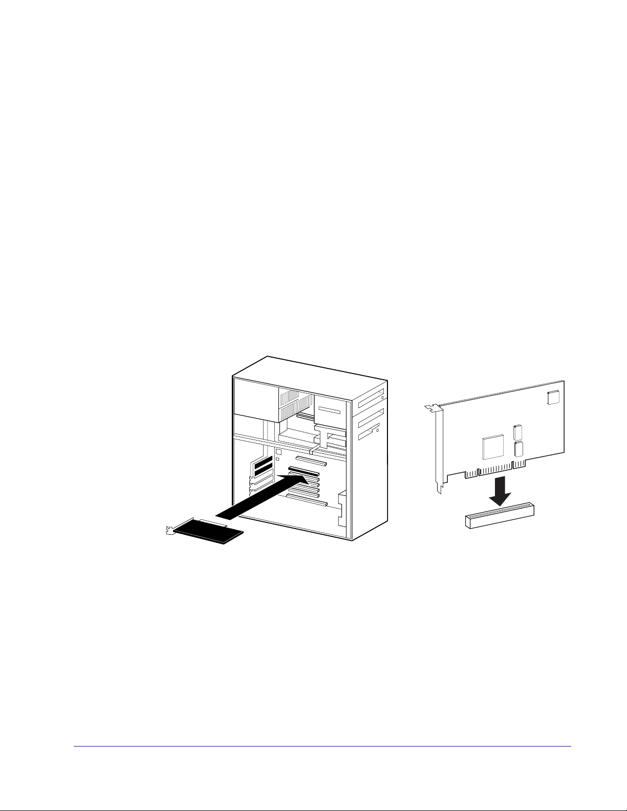
6. Hold the card gently by the top edges, and line up its PCI connector with
the PCI slot inside the computer.
Figure 1. UAD-1 card installation
7. When the connector and slot are aligned, press the card into the slot using
firm, even pressure. The card should “pop” into place. The top of the PCI
slot on the motherboard should be flush and parallel with the edge of the
UAD-1 card.
8. Secure the card with the previously removed screw.
9. Replace the computer case
Hardware installation is now complete.
UAD-1 Powered Plug-Ins Manual - 20 - Installation
Page 21

CHAPTER 3
Using UAD-1 Powered Plug-Ins
Overview
Once the UAD-1 card and Powered Plug-Ins have been properly installed, the
UAD-1 Powered Plug-Ins are accessed and used just like any host-based plugin. All UAD-1 Powered Plug-Ins can run concurrently with each other and
with host-based plugins simultaneously, in any combination.
All UAD-1 Powered Plug-Ins support up to 32-bit, 192KHz operation. Resolution is limited only the by resolution of the host application. Please note that
Powered Plug-Ins running at 96KHz use twice as much UAD-1 DSP resources
than those used at 48KHz, and so forth.
Adjusting Parameters
Text Entry Parameter values can be modified directly with text entry. To enter a param-
The parameter settings for each of the UAD-1 Powered Plug-Ins can be adjusted to achieve a desired effect. Parameter values are easily modified by
dragging sliders, rotating knobs, clicking switches and buttons, or by selecting values in a pop-up menu. The function of all parameters are detailed in
later chapters.
The parameter adjustment style can be Circular, Relative Circular, or Linear.
For more information, see “User Interface Settings” on page 35.
Note: To increase resolution when adjusting rotary controls in circular and
relative circular modes, increase the radius of the mouse relative to the knob
while dragging (i.e. move the mouse farther away from the knob while dragging).
eter value using text entry, single-click the parameter value text. The text value
will highlight indicating it is ready to receive a new value. Type in a new
value, then press Return, Enter, or Tab, or click outside of the text box. Press
Esc if you want to revert to the prior setting without entering the new value.
Values entered via text entry are rounded to the closest significant digit. If an
entered value is out of range, it will be ignored.
To enter time values, the units must be specified. m =milliseconds, and s = seconds. Examples: 400 milliseconds = .400s or 400m; 1.5 seconds = 1.5s or
1500m.
UAD-1 Powered Plug-Ins Manual - 21 - Using UAD-1 Powered Plug-Ins
Page 22

Scroll Wheel If your mouse has a scroll wheel, it can be used to adjust knob and slider con-
trols. Place the mouse cursor over any knob or slider control to increment or
decrement the parameter value with the scroll wheel. This feature is not supported under Mac OS due to a limitation of the system software.
Keyboard
Control
(Mac OS)
If you control-click a control it selects that control for keyboard control. This is
useful for when you're in circular mode, and you want to fine-adjust a control.
Normally, clicking on a control in this mode makes the value jump to where
you clicked. Control-clicking will select the control so that you can use the keyboard to adjust it, without making its value jump first.
Shortcuts Table 1 lists the keyboard shortcuts that are available for modifying parame-
ter values. When using keyboard shortcuts, the last edited control will be modified (or, on Mac OS, you can use control-click to select a different control as
the target for keyboard shortcuts without changing the control's value).
Note: Not all host applications support sending keystrokes to plugins.
Table 1. Keyboard shortcuts
Keyboard Action: Result:
Control + Click Parameter (Mac OS only) Select parameter for keyboard control
(without changing its value)
Shift + Drag Fine Control
UpArrow
RightArrow
Shift + PageUp
Increment Fine
DownArrow
LeftArrow
Shift + PageDown
Shift + UpArrow
Shift + RightArrow
PageUp
Shift + DownArrow
Shift + LeftArrow
PageDown
Home Maximum
End Minimum
Control + Click parameter (Windows)
Modifier* + Click parameter (Mac OS)
(*Modifier key set in Configuration Window)
Control + Shift + Click parameter (Windows)
Modifier* + Shift + Click parameter (Mac OS)
(*Modifier key set in Configuration Window)
UAD-1 Powered Plug-Ins Manual - 22 - Using UAD-1 Powered Plug-Ins
Decrement Fine
Increment coarse
Decrement coarse
Toggle initial editor setting (the value when the
editor window was last opened)
Revert to initial editor setting (the value when the
editor window was last opened)
Page 23
Automation Every UAD-1 Powered Plug-In parameter can be automated if this feature is
supported by the host application. Each host application has its own particular methods for automation. Consult the host application documentation for
specific instructions on using automation with the application.
Powered Plug-Ins reduce their UAD-1 DSP load when bypassed or disabled,
but not their memory load. This feature allows for automatable load balancing of DSP power, and keeps the track delay constant to avoid on/off clicks.
Note: If there is not enough DSP available when automating, the plugin may
not turn on.
UAD-1 Powered Plug-Ins Manual - 23 - Using UAD-1 Powered Plug-Ins
Page 24
Launching a UAD-1 Powered Plug-In
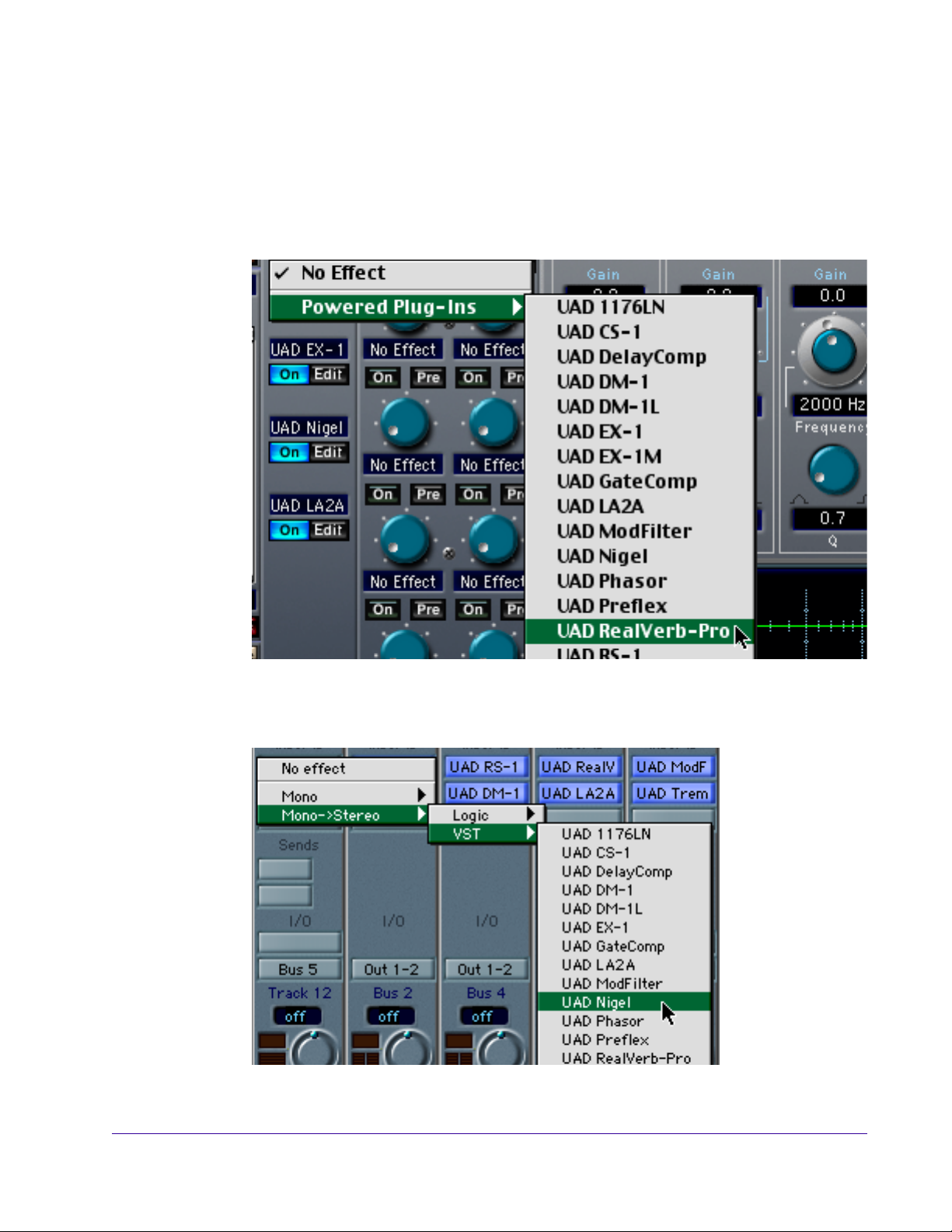
Each host application has its own particular methods for instantiating (launching) a plugin. Consult the host application documentation for specific instructions on loading and using plugins with the application.
Steinberg Cubase/Nuendo
Emagic Logic Audio
Figure 2. Launching a UAD-1 Powered Plug-In in Steinberg Cubase and Nuendo
Figure 3. Launching a UAD-1 Powered Plug-In in Emagic Logic Audio
UAD-1 Powered Plug-Ins Manual - 24 - Using UAD-1 Powered Plug-Ins
Page 25
UAD-1 DSP Performance Meter Application
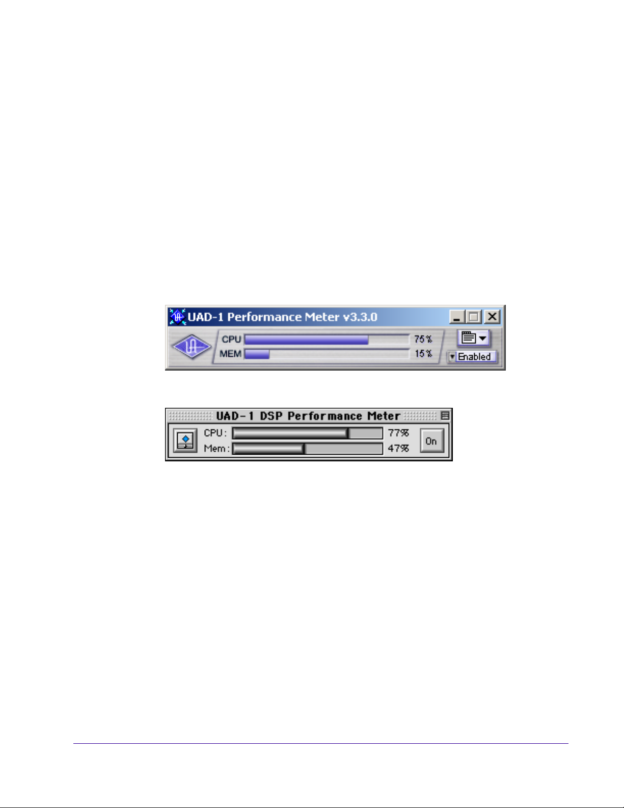
Overview The UAD-1 Performance Meter is an application that displays the current CPU
and memory status of the UAD-1 DSP hardware card in realtime. Its small
floating window enables you to monitor the resource load of the UAD-1, while
simultaneously using your host application.
It also contains system information and configuration windows that enable
you to confirm the UAD-1 is functioning properly, check the version of the software drivers, and adjust the UAD-1 buffers.
If multiple UAD-1 cards are installed, the displayed CPU and memory usage
is the total for all installed cards. Usage statistics of individual cards can be
viewed using the System Information window (see page 30).
Launching the
Meter
Windows
Figure 4. The UAD-1 Performance Meter application window (Windows)
Figure 5. The UAD-1 Performance Meter application window (Mac OS)
To launch the UAD-1 Performance Meter application in Windows:
1. Double-click the UAD-1 Meter shortcut that was placed on the Desktop dur-
ing installation. OR,
2. Access the application from the Start Menu at Programs/UAD-1 Powered
Plug-Ins/UAD-1 Meter. OR,
3. Double-click the executable file on the hard drive located at C:Program
Files/Universal Audio/Powered Plug-Ins/UADPerfMon.exe.
UAD-1 Powered Plug-Ins Manual - 25 - Using UAD-1 Powered Plug-Ins
Page 26
Launching the
To launch the UAD-1 Performance Meter application in Mac OS:
Meter
Mac OS
1. Double-click the UAD-1 Meter alias that was placed on the Desktop (OS 9)
or in the Dock (OS X) during installation. OR,
2. Double-click the UAD-1 Meter application file that was copied to your hard
drive inside the Powered Plug-Ins Tools folder during installation.
Accessing Meter Functions
The UAD-1 DSP Performance Meter view mode, System Information Window,
and Configuration Window functions are accessed from the System menu
(Windows) or the File menu (Mac OS). After clicking the System or File menu
with the mouse, the available functions are listed in the menu.
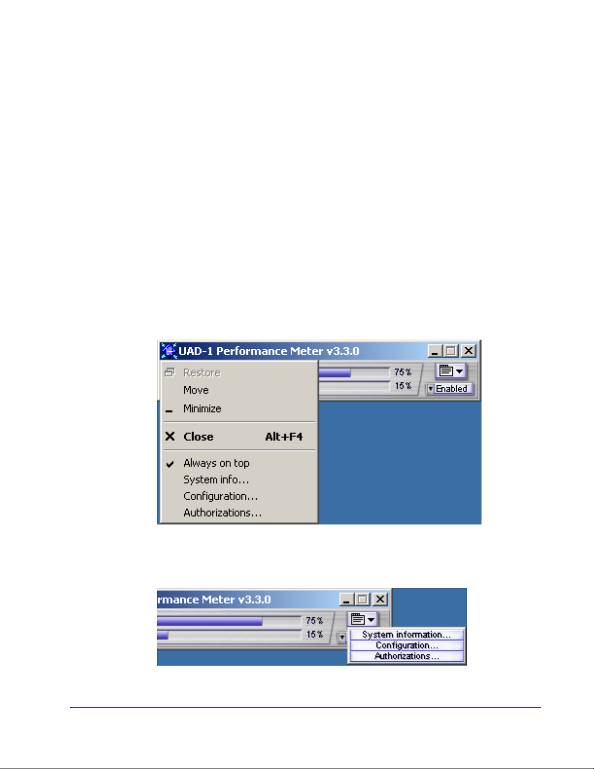
Windows Open the system menu by clicking the small icon at the upper left of the UAD-
1 DSP Performance Meter window, or the alternate system menu on the right
side of the Meter window, just above the Disable menu.
Figure 6. System menu for the UAD-1 Performance Meter (Windows)
Figure 7. Alternate system menu for the Meter (Windows)
UAD-1 Powered Plug-Ins Manual - 26 - Using UAD-1 Powered Plug-Ins
Page 27
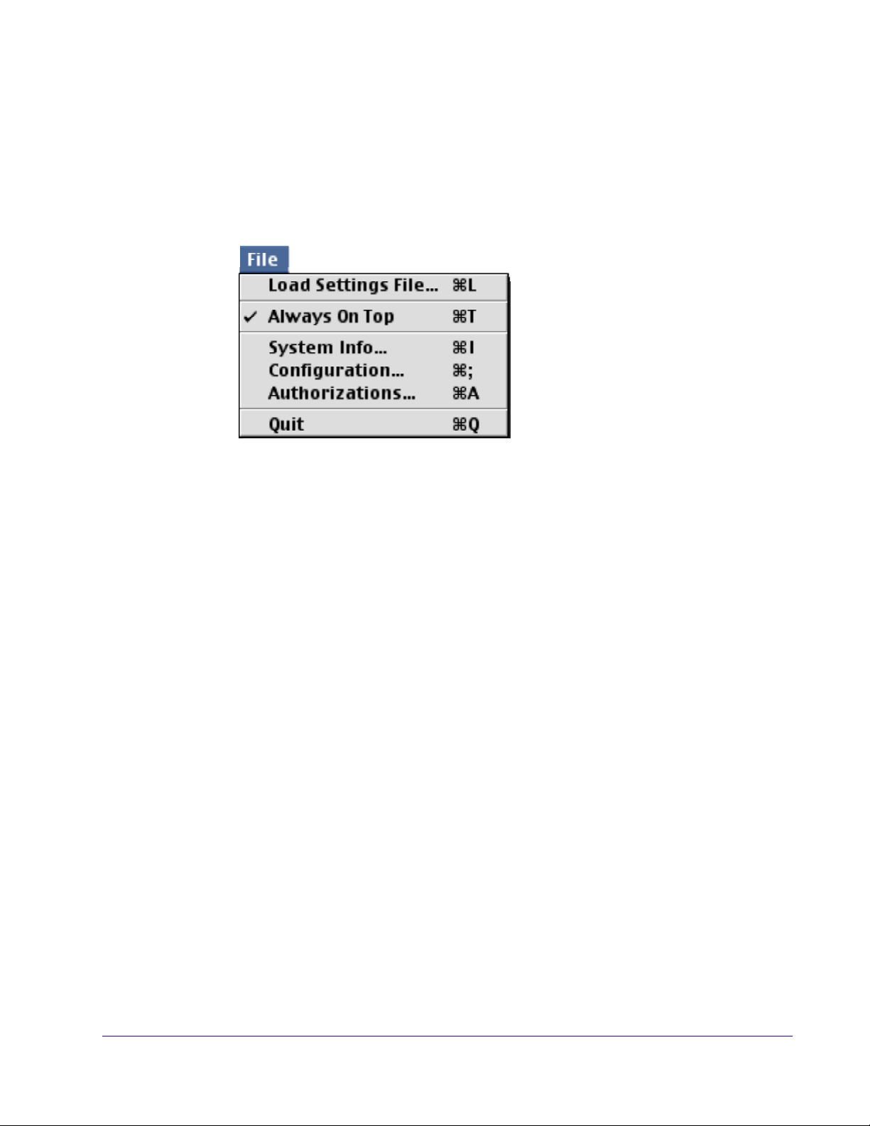
Mac OS The File menu is available when the UAD-1 DSP Performance Meter is in the
foreground. When the UAD-1 Performance Meter application is in the foreground, toggle the ‘Always on top’ item in the File Menu (or type the Command + T shortcut). You can easily bring the Meter to the foreground by clicking the Bring to Front button (see Figure 9 on page 29).
Figure 8. File Menu for UAD-1 Performance Meter (Mac OS)
Using the Meter
The UAD-1 DSP Performance Meter can be launched or quit at any time. It
does not need to be open or active to use UAD-1 Powered Plug-Ins. It is completely independent of any other applications and does not require a host application. Move the Performance Meter to a convenient location on your
screen by dragging its window title bar.
The CPU gauge indicates the percentage of UAD-1 DSP that is currently in
use. It indicates the total available UAD-1 DSP statistics, regardless of the
number of UAD-1 cards that are installed. When UAD plugins are disabled,
DSP requirements are decreased.
The Memory gauge indicates the percentage of UAD-1 memory that is currently in use. It indicates the total available UAD-1 memory available, regardless of the number of UAD-1 cards that are installed. When UAD plugins are
disabled, memory requirements are not decreased. In this case, memory remains loaded so that reverb tails and delay lines are not cut off when the plugin is disabled.
UAD-1 Powered Plug-Ins Manual - 27 - Using UAD-1 Powered Plug-Ins
Page 28
Always On Top The Performance Meter window can be set to a normal or ‘Always On Top’
view mode. In normal mode, the window can be covered by windows of the
foreground application. When in ‘Always on top’ mode, the Performance
Meter window always floats on top of other windows, even when other applications are in the foreground, so you can always see the meter and access
the Enable Menu (Windows) and On/Off button (Mac OS). This setting is
saved when the meter is quit.
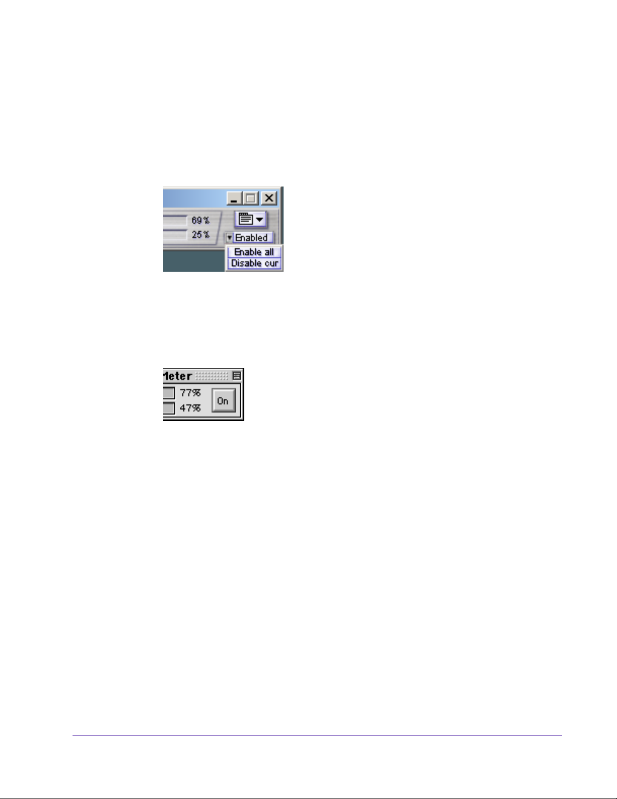
Enable Menu
(Windows)
On/Off Button
(Mac OS)
The Enable Menu allows you to disable all UAD-1
Powered Plug-Ins that are currently running. This enables you to add new plugins for offline processing
if the UAD-1 is low on DSP, or easily compare the
sound of the processed and unprocessed audio.
When the menu displays “Enabled” all UAD-1 plugins are active. Select “Disable current” from the menu to disable the active plugins. New UAD-1 plugins
can then be added. Select “Enable all” to re-activate all UAD-1 plugins.
The On/Off button allows you to disable all UAD-1 Powered Plug-Ins that are currently running. This enables you
to add new plugins for offline processing if the UAD-1 is
low on DSP, or easily compare the sound of the processed
and unprocessed audio.
When the button displays “On” all UAD-1 plugins are active. Click the button
to disable the active plugins. New UAD-1 plugins can then be added. Click
the button again to reactivate the plugins.
Bring to Front
Button (Mac OS)
To access the File menu of the Performance Meter application, the application
must be in the foreground. The “Bring To Front” shortcut button (see Figure 9
on page 29) makes this easy by immediately bringing the Performance Meter
application to the foreground when clicked, saving a mouse trip to the Mac
OS application menu.
UAD-1 Powered Plug-Ins Manual - 28 - Using UAD-1 Powered Plug-Ins
Page 29
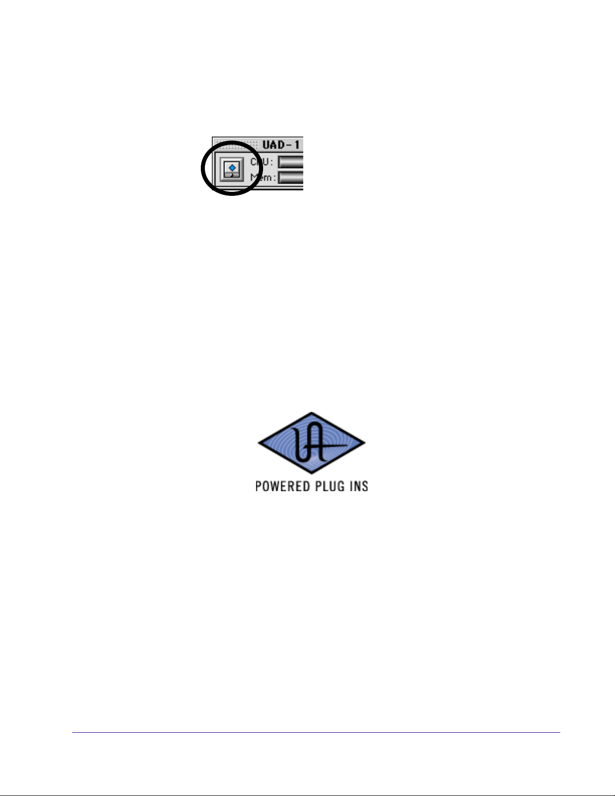
Note: The “Bring To Front” button is only present when the Performance
Meter is in “Always On Top” mode. When the Performance Meter is not in
this mode, the application comes to the foreground whenever you click anywhere in the Performance Meter window.
Figure 9. Performance Meter Bring to Front button (Mac OS)
UAD-1 Powered Plug-Ins Manual - 29 - Using UAD-1 Powered Plug-Ins
Page 30

UAD-1 System Information Window
The UAD-1 System Information window (Figure 10 on page 31 and
Figure 11 on page 32) displays the version of the UAD-1 software drivers in
use by the UAD-1 hardware and also allows you to confirm that the card is
working properly. When the window displays UAD-1 Status: OK and UAD-1
DSP: OK, the card is operating properly. The number of UAD-1 plugins
loaded on the card(s) is also displayed here.
If more than one UAD-1 card is installed, information for each of the cards is
displayed. The card that has the lowest DSP usage will receive the next plugin
load.
Important: The version of the UAD-1 Drivers and the Powered Plug-Ins files
must match. If they don’t, a “driver mismatch” error will occur when attempting to process audio. If this occurs, you must reinstall the latest UAD-1 Powered Plug-Ins software. Refer to the QuickStart Guide for instructions
Card Enabled Individual UAD-1 cards can be disabled using the Card Enabled function.
This can be useful, for example, if creating a session on a system with multiple
cards that will be transferred to a system with fewer cards or to streamline the
performance of the host system when multiple cards are not needed.
For additional information regarding the use of multiple cards, see “Multiple
Cards” on page 48.
Note: For optimum results, quit any host applications using UAD-1 plugins
before disabling/enabling cards.
In Mac OS, the current UAD-1 plugin latency is displayed in the System Information window. In Windows, this information is displayed in the Configuration window (page 38). The latency is usually twice the hardware buffer size.
Windows Click a card column to view more information about that card in the status
area. If a card has errors, the error information for that card is automatically
displayed in the status area without having to click its card column.
UAD-1 Powered Plug-Ins Manual - 30 - Using UAD-1 Powered Plug-Ins
Page 31

System Info
(Windows)
Figure 10. The UAD-1 System Information window (windows)
UAD-1 Powered Plug-Ins Manual - 31 - Using UAD-1 Powered Plug-Ins
Page 32

System Info
(Mac OS)
Figure 11. The UAD-1 System Information window (Mac OS)
UAD-1 Powered Plug-Ins Manual - 32 - Using UAD-1 Powered Plug-Ins
Page 33

UAD-1 Configuration Window
The UAD-1 Configuration Window (Figure 13 on page 38 and Figure 12 on
page 37) displays additional information about the UAD-1 card and is also
used to modify some UAD-1 settings.
Latency Calculator
DMA Settings
(Windows)
The number of active UAD-1 Powered Plug-Ins, the sample rate, and the current buffer size are displayed. The window uses this information to calculate
and display the resulting latency in milliseconds. In Mac OS, the latency calculator is displayed in the System Information window.
Configuring Extra Buffers
Extra Buffers are required when “Buffer Size” displayed in the UAD-1 Configuration Window is smaller than the actual ASIO buffer size selected for the
active ASIO hardware device.
Note: Extra Buffers are not required for Cubase/Nuendo version 2 or
higher, Logic Audio, or Mac OS.
This situation may occur when users of Steinberg Cubase and Nuendo select
ASIO buffer sizes of 2048 samples or greater, or when UAD-1 Powered plugIns are used with a DirectX wrapper. If the situation is not corrected, the use
of UAD-1 Powered Plug-Ins will introduce excess host CPU load.
To configure the UAD-1 for Cubase and Nuendo large ASIO buffer size support:
1. Launch the UAD-1 Performance Meter.
2. Open the system menu by clicking the icon at the upper left of the Perfor-
mance Meter and select the ‘Configuration’ option.
3. Increase the Extra Buffers control until “New latency” matches the current
buffer size of the ASIO device.
4. Reset the ASIO device using one of the following methods:
•Close the re-open the session
•Stop then restart the audio engine
•Modify or reset the audio device settings
5. The “Current latency” display should now match the “New latency” dis-
play. Configuration of Extra Buffers is complete.
UAD-1 Powered Plug-Ins Manual - 33 - Using UAD-1 Powered Plug-Ins
Page 34

AMD-8131 Mode
If your computer uses the AMD-8131 PCI controller chipset, check the “AMD8131 Compatible” box. This will improve UAD-1 performance on these systems. For the new setting to take affect, you must reset the ASIO device using
one of the following methods:
•Close the re-open the session
•Stop then restart the audio engine
•Modify or reset the audio device settings
Note: Do not enable AMD-8131 Mode unless your computer uses this PCI
controller chipset. AMD-8131 Compatible Mode is only required when the
card is attached directly to an AMD-8131 PCI bus. If the UAD-1 is in an external PCI expansion chassis, this mode should be disabled.
The AMD-8131 chipset is also used in Macintosh G5 systems. However, the
UAD-1 software automatically determines when it is running on a G5 and sets
the mode appropriately, therefore there is no corresponding checkbox in the
Mac OS Configuration Window.
DSP Settings These controls limit the maximum UAD-1 CPU load before no more plugins
will be processed by the UAD-1.
CPU load limiting was introduced in version 3.0. The option is off by default
so sessions with heavy UAD-1 loads that have been saved with UAD-1 software versions previous to 3.0 will playback without any UAD-1 plugins being
disabled due to overload.
Without UAD-1 Powered Plug-Ins installed, overloading the host system with
native (host based) plugins can cause dropouts and possibly system lockup.
Steinberg hosts, for example, provide a switch that allows you to trade latency for stability when the system is overloaded. Similarly, the UAD-1 DSP
load cannot exceed 100% without unpredictable behavior.
With the Limit CPU Load feature, the UAD-1 CPU can also be limited so the
load cannot exceed 100%, thereby increasing overall system stability in high
load situations. With very heavy UAD-1 loads, CPU load limiting may also improve host CPU performance.
UAD-1 Powered Plug-Ins Manual - 34 - Using UAD-1 Powered Plug-Ins
Page 35

There are many variables that affect DSP load (sample rate, bit depth, buffer
size, parameter values, mono/stereo, automation, host system, etc). Although
these variables are taken into account, the resulting measurement cannot be
absolutely accurate. This is due to variations in system configurations, specifically PCI bus loading which is impossible to predict. Systems that are heavily
loaded due to the presence of other devices or suboptimal configuration may
cause additional DSP loading that cannot be predicted by the plugin load calculator. The CPU load limit should be reduced in this case.
It is possible for certain (non-typical) conditions to be met where another
UAD-1 plugin can’t be added, even when the UAD-1 Meter says you should
have CPU available when compared to the CPU Load Limit value.
Limit CPU Load
UAD-1 CPU Load Limiting is enabled when this box is checked.
CPU Load Limit
This setting controls the maximum UAD-1 CPU when load limiting is enabled.
It has no affect when CPU load limiting is off.
User Interface Settings
Controls Mode
This setting determines how Powered Plug-In parameter knobs respond to adjustment. Three control modes are offered: Circular, Relative Circular, and Linear.
Note: To increase resolution when in adjusting rotary controls in circular and
relative circular modes, increase the radius of the mouse relative to the knob
while dragging (i.e. move the mouse farther away from the knob while dragging in a circular motion).
UAD-1 Powered Plug-Ins Manual - 35 - Using UAD-1 Powered Plug-Ins
Page 36

Circular (jump)
In Circular mode, the software knobs behave similar to physical knobs. Values are changed by clicking on the knob then rotating in a circular direction.
When the edge of the knob is clicked, the parameter value jumps to the
mouse position.
Relative Circular (grab)
Relative Circular mode operates similar to Circular mode, but the knob value
does not jump to the mouse position when clicked. Instead, the knob value is
modified relative to its original value.
In this mode you can click anywhere on the knob to make an adjustment originating at the original value. You don’t have to click on the current knob position.
Linear (slider)
In Linear mode, the knob is adjusted by dragging horizontally or vertically instead of by rotating. This behavior is similar to moving a slider.
Use Host Mode
Modifier Key
(Mac OS)
When Use Host Mode is checked, the control mode set within the host application preferences is used if this feature is supported by the host. This setting
forces the host to override the control mode set in the UAD-1 user interface settings.
Note: When Use Host Mode is checked, the UAD-1 Meter user interface set-
tings have no effect unless control mode is NOT supported by the host.
The Modifier Key drop-menu allows you to specify which modifier key will be
used for the “set to last saved value” keyboard shortcut. It also affects the “select + click” modifier. This feature is not supported under Windows. For a
complete list of keyboard shortcuts, see “Shortcuts” on page 22.
UAD-1 Powered Plug-Ins Manual - 36 - Using UAD-1 Powered Plug-Ins
Page 37

PCI Bus Settings This parameter adjusts a low-level system setting and should never need to be
modified. It is provided for technical support purposes only.
Important: System performance can be adversely affected by changing this
setting. This parameter DOES NOT AFFECT AUDIO LATENCY in any way!
Configuration
Window
(Mac OS)
Figure 12. The UAD-1 System Configuration window (Mac OS)
UAD-1 Powered Plug-Ins Manual - 37 - Using UAD-1 Powered Plug-Ins
Page 38

Configuration
Window
(Windows)
Figure 13. The UAD-1 System Configuration window (windows)
UAD-1 Powered Plug-Ins Manual - 38 - Using UAD-1 Powered Plug-Ins
Page 39

Delay Compensation
Overview When UAD-1 Powered Plug-Ins are used, audio data to be processed by a
Powered Plug-In is sent by the host application to the UAD-1 card. The audio
is then processed by the UAD-1 card and sent back to the host application.
This back-and-forth shuffling of audio data produces a latency (delay) in the
audio signal being processed. Latency time is determined by the sample rate,
the hardware device driver (ASIO or similar) buffer setting, and the Extra Buffers (if any) in the UAD-1 Configuration window.
If this latency is not compensated, the processed audio will not be perfectly
synchronized with unprocessed audio. Fortunately, most host applications automatically compensate for this latency when plugins are used on track inserts
by simply turning on the “Plugin Delay Compensation” or similar Preferences
setting. Some hosts even provide “Full Delay Compensation” throughout the
entire signal path, including sends, groups, and busses.
However (depending on the host application implementation), the delay compensation feature may not provide automatic compensation when UAD-1
Powered Plug-Ins are inserted on sends, groups, or busses. In this situation,
the solution is to use the UAD Delay Compensator plugin (“UAD Delay Com-
pensator plugin” on page 40).
Host Application Settings
Note: These explanations of delay compensation apply primarily to play-
back only. For more information about using UAD-1 Powered Plug-Ins for live
performance and during recording, “Live Processing” on page 47.
Note: For information about using UAD-1 Powered Plug-Ins on audio tracks
while simultaneously running MIDI tracks, “UAD Track Advance” on
page 44.
For optimum results, the “Plugin Delay Compensation” option setting should
be active in the host application. This will provide automatic latency compensation when UAD plugins are used on track inserts (and sends/group/busses
if full compensation is supported), so the UAD DelayComp will not have to be
used. This option is usually found in the audio or plugin preferences window.
The specific location of the switch for this option within several popular applications is as follows:
•Cubase: Options Menu>Audio Setup>System...
•Nuendo: File Menu>Preferences>VST
•Logic Audio: Audio Menu>Audio Preferences...
UAD-1 Powered Plug-Ins Manual - 39 - Using UAD-1 Powered Plug-Ins
Page 40

UAD Delay Compensator plugin
Overview The UAD Delay Compensator (DelayComp for short) is a simple plugin which
can be used to synchronize unprocessed tracks with those that are processed
by UAD-1 Powered Plug-Ins. It provides a mechanism of delay compensation
for situations when the host application does not implement automatic plugin
latency compensation, such as on sends, groups, and busses.
Note: UAD DelayComp should not be used in situations where the host ap-
plication provides delay compensation automatically, such as on track inserts. Some host applications provide fully automatic delay compensation
throughout the entire signal path. UAD DelayComp is not needed at all in
such hosts. As of this writing, hosts with fully automatic compensation include
all DirectX hosts, Steinberg Nuendo/Cubase 2.x, and Magix Samplitude 7.x.
The UAD Delay Compensator acts as a dummy UAD-1 Powered Plug-In, automatically introducing the necessary amount of latency for tracks which are
NOT processed by UAD-1 Powered Plug-Ins. It requires no DSP from the host
CPU or the UAD-1 card and allows you specify the number of UAD-1 Powered
Plug-Ins instances you wish to compensate.
Figure 14. The UAD Delay Compensator plugin window
When to use DelayComp
UAD DelayComp should be used whenever unprocessed audio tracks are
played alongside audio tracks that are assigned to a send/group/bus that is
using a UAD plugin(s). In this scenario, inserting a UAD DelayComp plugin
on the UNPROCESSED track(s) will automatically re-synchronize the audio.
VSTi Cubase and Nuendo currently do not automatically compensate for latency
on MIDI virtual instrument (VSTi) tracks. Therefore, UAD DelayComp should
also be used on non-VSTi tracks when VSTi’s are in use.
Note: Check out our UAD DelayComp Examples on the UAD-1 Powered
Plug-Ins CD-ROM (or download them from our website) for “real-world” examples formatted for several popular host applications.
Note: When the UAD Pultec EQ is being used in conjunction with Delay-
Comp, the Samples parameter should be used in addition to the Plugs parameter (“Compensating for Pultec EQ” on page 43).
UAD-1 Powered Plug-Ins Manual - 40 - Using UAD-1 Powered Plug-Ins
Page 41

Plugs parameter The DelayComp Plugs parameter value to be used on an unprocessed track or
tracks is simply the number of UAD-1 Powered Plug-Ins that are being used in
sequence on the send, group, or bus.
For example, if three separate sends are used and each send has one instance of UAD plugins, the Delay Compensator Plugs value for the unprocessed tracks would be one. However, if one send/group/bus is used that has
three instances of UAD-1 Powered Plug-Ins stacked up, the Delay Compensator Plugs value for the dry tracks would be three.
Note: The Delay Compensator “Plugs” value matches the total of UAD-1
Powered Plug-Ins used serially (stacked one above another in series), NOT the
total number of UAD-1 Powered Plug-Ins used.
Samples parameter
Grouping Tracks Requiring DelayComp
The Samples parameter shifts the audio with single-sample accuracy in either
direction. It is provided mainly for compensation of the Pultec EQ (“Compen-
sating for Pultec EQ” on page 43 for more information). However, it can be
used anytime minute shifting of audio is desired. Audio can be shifted up to
128 samples in either direction.
Note: The keyboard shortcuts PageUp/PageDown and Shift+Arrow auto-
matically add the 13-sample Pultec value for your convenience.
The UAD DelayComp plugin is generally used on track inserts. However,
when many tracks require delay compensation, instead of placing individual
Delay Compensator plugins on each track you may find it easier to send the
output of each unprocessed tracks to a bus or group. Then simply put one
UAD Delay Compensator on that bus or group.
UAD-1 Powered Plug-Ins Manual - 41 - Using UAD-1 Powered Plug-Ins
Page 42

DelayComp Examples
Insert Situation: You have a song with bass, drums, and guitar. You want a room
simulator on the guitar so you put an RS-1 on an insert of the guitar track. Result: All tracks are perfectly aligned.
Solution: None needed. Delay compensation on track inserts is handled automatically by most host applications.
Send Situation: You have a song with bass, drums, guitar, and 2 vocal tracks. You
want a fantastic reverb on the vocals so you send both vocal tracks to the UAD
RealVerb Pro via an effect send. Result: The RealVerb Pro effect return plays
late in relation to the dry tracks.
Solution: Send the output of all the tracks (including the dry vocal tracks but
NOT the RealVerb Pro return) to a different send/group/bus and put one
UAD DelayComp with a Plugin value of 1 on this send/group/bus that contains the dry tracks. Keep the Sample value at zero.
Group/Bus Situation: You have a song with bass, drums, guitar, and 2 vocal tracks. You
want a smoother vocal blend so you put both vocal tracks on a group/bus for
compression with the infamous LA2A. Result: The vocal tracks play late in relation to the instrument tracks.
Solution: Send the output of the unprocessed instrument tracks (but not the vocal tracks or LA2A return) to a different group/bus and put one DelayComp
with a Plugin value of 1 on this group/bus that contains the unprocessed
tracks. Keep the Sample value at zero.
Note: Some host applications provide fully automatic delay compensation
throughout the entire signal path. UAD DelayComp is not needed at all in
such hosts. As of this writing, hosts with fully automatic compensation include
all DirectX hosts, Steinberg Nuendo/Cubase 2.x, and Magix Samplitude 7.x.
Note: Check out our UAD DelayComp Examples on the UAD-1 Powered
Plug-Ins CD-ROM (or download them from our website) for “real-world” examples formatted for several popular host applications.
UAD-1 Powered Plug-Ins Manual - 42 - Using UAD-1 Powered Plug-Ins
Page 43

Compensating for Pultec EQ
The Pultec EQ uses an internal sample rate of 192kHz to achieve its magic
quality. This upsampling results in a slightly larger latency than other UAD-1
plugins. Therefore, it requires slightly more compensation to remain perfectly
synchronized with other tracks. Specifically, it requires an extra 13 samples
of compensation.
Therefore, when using the DelayComp or TrackAdv plugin on sends, groups,
and busses to compensate a Pultec EQ, enter a Samples value of 13 for each
instance of Pultec.
Note: Compensating for Pultec EQ is required even if the host application
supports “full delay compensation” throughout the signal path.
Note: When running audio at 192kHz resolution, no Pultec upsampling is
performed. In this case, leave the Samples value at zero.
Note: The keyboard shortcuts PageUp/PageDown and Shift+Arrow auto-
matically add the 13-sample Pultec value for your convenience.
Pultec Group/Bus Example
Situation: You have a song with bass, drums, guitar, and 2 vocal tracks. You
want a fat, warm vocal blend so you put both vocal tracks on a group/bus
and apply one instance of Pultec EQ to the vocal bus. Result: The vocal tracks
play late in relation to the instrument tracks.
Solution: Send the output of the unprocessed instrument tracks (but not the vocal tracks or the Pultec return) to a different group/bus, and put one DelayComp with a Plugin value of 1 and a Sample value of 13 on this group/bus
that contains the dry non-vocal tracks. If you put 2 Pultec EQ’s stacked in series on the vocal bus, the unprocessed bus DelayComp Plugin value would be
2, and the Sample value would be 26.
UAD-1 Powered Plug-Ins Manual - 43 - Using UAD-1 Powered Plug-Ins
Page 44

UAD Track Advance
Overview The previous discussions on delay compensation (see “Delay Compensation”
on page 39) apply mainly when using only audio tracks. When MIDI tracks
are played simultaneously alongside audio tracks, a different (but related)
synchronization issue can arise.
Let’s say you have a MIDI track and an audio track with a UAD plugin on the
audio track insert. In this scenario, the host application will automatically
compensate for latency and no use of the UAD DelayComp or UAD Track Advance is required.
However, if the audio track is sent to a send/group/bus and that
send/group/bus has a UAD plugin on it, the audio track will be delayed in
relation to the MIDI track because the host does not compensate for latency
automatically on groups/busses. If the MIDI track was an audio track, you
would use the UAD DelayComp on it to compensate for the latency. But you
can’t put a UAD DelayComp on a MIDI track, so what to do?
Enter the UAD Track Advance plugin (TrackAdv for short). It operates just like
the DelayComp plugin, but backwards. Instead of delaying unprocessed
tracks, it shifts them forward. It does this by reporting to the host application
that a track has a UAD plugin on it, so the host compensates for the latency.
However, the track audio is not actually processed by the UAD-1 so the net result is that the audio plays early.
Figure 15. The UAD Track Advance plugin window
Note: The Track Advance plugin only works in hosts that support automatic
delay compensation. This is why the MAS version does not include UAD
TrackAdv.
UAD-1 Powered Plug-Ins Manual - 44 - Using UAD-1 Powered Plug-Ins
Page 45

When to use TrackAdv
UAD TrackAdv should be used whenever MIDI tracks are played alongside
audio tracks that are assigned to a send/group/bus that is using UAD plugin(s).
How to use TrackAdv
UAD TrackAdv is designed to be used on audio track inserts of tracks that are
assigned to a send/group/bus that has one or more UAD plugins applied. By
first advancing the audio with TrackAdv on the track insert then processing
the same track on a send/group/bus that has a UAD plugin, the “net latency
result” is zero and the audio will be perfectly aligned with the MIDI tracks.
Plugs parameter The TrackAdv Plugs parameter value to be used on a track insert is simply the
number of UAD plugins that are being used in sequence on the send, group,
or bus that the track is assigned to.
For example, if three separate sends are used and each send return has one
instance of UAD plugins, the TrackAdv Plugin value for the audio tracks insert
would be one. However, if one send/group/bus is used that has three instances of UAD-1 Powered Plug-Ins stacked up, the TrackAdv Plugs value for
the tracks inserts would be three.
Note: The TrackAdv “Plugs” value on the track insert matches the total of
UAD-1 Powered Plug-Ins used serially (stacked one above another in series)
on the send/group/bus that the track is assigned to, NOT the total number of
UAD-1 Powered Plug-Ins used.
Samples parameter
The Samples parameter shifts the audio with single-sample accuracy in either
direction. It is provided mainly for compensation of the Pultec EQ (“Compen-
sating for Pultec EQ” on page 43 for more information). However, it can be
used anytime minute shifting of audio is desired. Audio can be shifted up to
128 samples in either direction.
Note: The keyboard shortcuts PageUp/PageDown and Shift+Arrow auto-
matically add the 13-sample Pultec value for your convenience.
UAD-1 Powered Plug-Ins Manual - 45 - Using UAD-1 Powered Plug-Ins
Page 46

TrackAdv Examples
Insert Situation: You have one track with MIDI and one track with audio. You put a
UAD plugin on the audio track. Result: All tracks are perfectly aligned.
Solution: None needed. Delay compensation on track inserts is handled au-
tomatically by most host applications.
Send Situation: You have a song with drums and guitar on audio tracks, and a MIDI
bass line. You want a cohesive room reverb on the audio tracks so you send
them to the UAD RealVerb Pro via an effect send. Result: The RealVerb Pro effect return plays late in relation to the MIDI track.
Solution: Put a TrackAdv plugin on the track insert of the audio tracks with a
Plugs value of 1. If you had an 1176LN and a RealVerb Pro on the send return, the TrackAdv Plugs value would be 2. Keep the Sample value at zero.
Group/Bus Situation: You have a song with 2 vocals on audio tracks, and a MIDI piano.
You want a smoother vocal blend so you put both vocal tracks on a
group/bus for compression with the infamous LA2A. Result: The vocal tracks
play late in relation to the MIDI track.
Solution: Put a TrackAdv with a Plugin value of 1 on the track inserts of the vocal tracks. Keep the Sample value at zero.
Situation: You have a song with drums, guitar, and 2 separate vocals on audio tracks, and a MIDI bass line. You want a smoother vocal blend so you put
both vocal tracks on a group/bus for compression with the 1176LN. Result:
The vocal tracks play late in relation to the instrument tracks.
Solution: First, send the output of the unprocessed audio tracks (but not the vocal tracks or LA2A return) to a different group/bus and put one DelayComp
with a Plugin value of 1 on this group/bus that contains the unprocessed
tracks. This aligns the audio tracks. Second, put a TrackAdv on the drum and
guitar track inserts with a Plugs value of 1. This aligns the audio tracks to the
MIDI track. Keep the Sample value at zero.
UAD-1 Powered Plug-Ins Manual - 46 - Using UAD-1 Powered Plug-Ins
Page 47

Live Processing
The previous discussion of delay compensation applies primarily to playback
and mixing of existing tracks. During recording (tracking), the primary concern usually centers around getting the absolute lowest possible latency out of
your hardware and software combination. The lower the latency is, the closer
you can get to a realtime, “ears match the fingers” performance situation in
the digital environment where some latency is unavoidable.
Minimizing realtime latency is simply a matter of setting the hardware device
driver (ASIO or similar) buffer setting as low as possible before system overloads or diminished audio quality (such as distortion) occurs. The manufacturer of the sound output device in use may offer additional tips for optimizing
latency on systems that use their hardware.
Note: Keep in mind the latency for each instance of UAD-1 Powered Plug-Ins
is equal to twice the current buffer size of the host system. This is because audio needs to travel to the UAD-1 card, then back again. For example, with a
buffer size of 256 samples, one Powered Plug-In will introduce 512 samples
of latency, and two Powered Plug-Ins in succession will introduce 1024 samples of latency.
DSP Usage
The UAD-1 card features an on-board CPU and 4 MB of memory for processing Powered Plug-Ins. The host system memory and CPU are never used for
Powered Plug-Ins processing. However, there will always be a small amount
of load on the host CPU induced by PCI data transfer and user interface operations. This is unavoidable when using a DSP card.
• UAD-1 CPU usage is proportional to the host application sample rate and
system PCI bus speed. Therefore, more plugins can be used simultaneously
in a 44.1K session than in a 96K session, and likewise a higher speed PCI
bus will use less CPU load than a slower bus.
• Bypassing individual components will conserve CPU. For example, bypassing the compressor in the EX-1 when only the EQ is in use, and/or bypassing any of the unused bands of the EX-1 EQ will use less UAD-1 CPU.
• The UAD-1 CPU resources required by each successive UAD-1 Powered
Plug-In instance will slightly decrease.
UAD-1 Powered Plug-Ins Manual - 47 - Using UAD-1 Powered Plug-Ins
Page 48

Multiple Cards
When multiple UAD-1 cards are installed in the host computer, the CPU and
memory load of the cards are automatically balanced dynamically in realtime. With multiple cards there is no major difference in operating procedures, except that more Powered Plug-Ins can be loaded in the session.
Note: For information about authorizing copy-protected plugins on multiple
cards, see “Authorizing Multiple Cards” on page 52.
Power Requirement
Up to four UAD-1 cards can be installed simultaneously in the host computer.
Each UAD-1 card uses a maximum of 14 watts of 5 volt power from the PCI
bus. The PCI specification provides for up to 25W per device, however some
host systems don't provide (or require) this much power.
Multicard Use The UAD-1 card that has the lowest resource usage will receive the next Pow-
ered Plug-In load. Note that an individual UAD-1 plugin cannot be split across
two (or more) UAD-1 cards.
For example, let’s say you have two UAD-1 cards installed, the UAD-1 Meter
displays 90%, you load another UAD-1 plugin that requires 6% CPU, yet you
get a “plugin unable to load” message. This would occur if both cards are already at 95% (the meter shows the total available CPU, not the per-card
CPU), so a 6% plugin can’t load.
System Info Window
UAD-1 CPU and memory resources used for each installed card, and the ability to enable/disable individual cards, is displayed in the System Information
window (see page 31).
Disabling Cards Individual UAD-1 cards can be disabled using the Card Enabled function (see
page 30). This can be useful, for example, if creating a session on a system
with multiple cards that will be transferred to a system with fewer cards.
Note: For optimum results, quit any applications using UAD-1 plugins before
disabling/enabling cards.
If a Powered Plug-In is loaded on a card then that card is subsequently disabled, an error message will be displayed. This occurs because a plugin is assigned to a card when it is first instantiated. It stays assigned to the same card
until it is de-instantiated (i.e. removed from the insert slot).
UAD-1 Powered Plug-Ins Manual - 48 - Using UAD-1 Powered Plug-Ins
Page 49

Host CPU Using more than one card can cause a slight increase in host CPU require-
ments, so disabling unused cards can help you squeeze in a bit more host performance if you need it. Using additional devices on the PCI bus requires host
resources, so running 15 UAD plugins on three cards at five plugins per card
may require more host CPU than running the same 15 UAD plugins on one
card.
For example, if you are trying to minimize latency during tracking by using a
smaller buffer size (which will increase host CPU) and need a bit more host
CPU, disabling one or more UAD-1 cards during tracking may give the extra
pinch of host CPU you need. The buffer size can then be increased and the
UAD-1 card(s) re-enabled for mixing.
UAD-1 Powered Plug-Ins Manual - 49 - Using UAD-1 Powered Plug-Ins
Page 50

Copy Protected Plug-Ins
Overview The UAD-1 Powered Plug-Ins software installation bundles always includes ev-
ery component that is part of the current software version, such as drivers, plugins, UAD-1 Meter application, and documentation. Version 3.4 includes
three copy-protected plugins, Cambridge EQ, DreamVerb, and Fairchild, that
can be authorized for an additional fee.
UAD Cambridge, UAD DreamVerb, and UAD Fairchild require authorization
for unlimited use. Without authorization, these plugins can be enabled to run
for 14 days without functional limitations in a timed demo mode (see “Demo
Mode” on page 54).
Purchasing To authorize the plugin for permanent unlimited use, an authorization key is
purchased on the internet via a web-based online store. To purchase authorizations, go to:
• http://www.uaudio.com/authorizations
Process To purchase a plugin, you must have an account on our secure web server at
my.uaudio.com (your account ID is your email address). You enter your information, including UAD-1 hardware identification number(s), into your account. Plugins can then be securely purchsed with a valid credit card or personal check.
After payment is received, a “.reg” settings file containing the authorization
key(s) can then be downloaded direcly from your personalized account
pages at my.uaudio.com. On the PC, this file is loaded into the host computer
containing the UAD-1 card by simply double-clicking the file. On Mac OS,
this file is dragged onto the UAD-1 Meter application icon (not the DSP/Memory bar graph window) or loaded using the “Load Settings File” menu item
from within the Meter.
The specific details of the authorization process is detailed later in this section
(see “Plug-In Authorization Procedure” on page 55).
Studio PAK The UAD-1 Studio PAK includes a license for all paid plugins. To authorize the
plugins for use with UAD-1 Studio PAK, see the license card inside the retail
box. It contains the required license code as well as instructions on how to obtain the authorization key files.
UAD-1 Powered Plug-Ins Manual - 50 - Using UAD-1 Powered Plug-Ins
Page 51

.reg Authorization Key File
The .reg file contains the authorization key(s) that allow a plugin to run on the
authorized cards, and is independent of the machine and operating system.
The authorizations can be used on multiple machines if the card is moved
around (for example, if a PCI expansion chassis is shared between a laptop
and desktop machine). These authorizations will remain valid even if the plugin software is subsequently replaced with the same or newer version, or if
any host system hardware or operating system changes are made.
The .reg files contain only the Hardware ID and authorization codes that enable a plugin to run on specific UAD-1 card(s). It does not contain other system information that restrict use of the cards or authorized plugins.
Note: It is the UAD-1 hardware that is authorized, not the software plugin.
If the UAD-1 card is installed into a different system, the same (already acquired) .reg file must be loaded into the different computer and the card becomes authorized to run the plugin on that system. The same UAD-1 and its associated .reg file can be loaded into an unlimited number of computer
systems (including Windows and Mac systems, as the card and key file are
cross-platform).
Important: The .reg settings file contains the authorization key for the spe-
cific UAD-1 card. It is required every time the card needs to be authorized,
such as if it is installed into a different computer. Back it up and keep it in a
safe place!
Mac OS In OS 9, once a card is authorized and it is used with a different System
Folder or CPU, you can copy the UAD Registry file (inside System Folder:Preferences) into the current System Folder:Preferences instead of loading the .reg
file. This has the advantage of not only copying your authorizations, but all
your other UAD-related preferences as well. In OS X, once a card is authorized and it is used with a different System or CPU, you can copy the
com.uaudio.uad.plist file (inside Library:Preferences) into the current Library:Preferences instead of loading the .reg file.
Order
Fulfillment
Timing
As of version 3.4, purchasing and downloading plugin authorizations is a
completely automatic process. Purchased plugin authorization keys can now
be downloaded within minutes of payment verification.
Note: We recommend you do not wait until the last day of demo period to
purchase plugin authorizations, in case there is a unexpected delay in obtaining authorizations.
UAD-1 Powered Plug-Ins Manual - 51 - Using UAD-1 Powered Plug-Ins
Page 52

Authorizing Multiple Cards
When you buy a copy-protected plugin, your purchase is valid for up to four
UAD-1 cards. However, the authorization key is tied to the specific Hardware
IDs entered during purchase. If you have four cards when you purchase the
plugin, your .reg file will authorize all four cards. If you have one card during
purchase then later acquire another card(s), you will need to acquire a new
.reg file containing the authorization for the new card(s). However, there is no
charge for the new .reg file containing the additional authorizations. Your
purchase buys authorizations for a maximum of four cards.
Each individual card must be authorized in order to run copy-protected plugins. If one card is authorized then another card is added without obtaining
a new .reg file, the copy-protected plugin will only load on the authorized
card.
To obtain a new .reg key file for additional cards, visit my.uaudio.com on the
internet.
If two cards are authorized at the same time then one is removed, the remaining card remains authorized. If you install an authorized card into another
system or want to use it with a different OS partition on the same system, you
will need to reapply any .reg files containing the card's authorizations on the
new system or OS partition.
UAD-1 Powered Plug-Ins Manual - 52 - Using UAD-1 Powered Plug-Ins
Page 53

Authorizations Window
The Authorizations window (Figure 16) is accessed within the UAD-1 Meter
application.
On Windows systems, access the Authorizations window from the System
Menu or alternate system menu. On Mac OS, use the File Menu. See “Access-
ing Meter Functions” on page 26” for specific instructions.
Hardware IDs
This section of the window is where the unique hardware identification numbers of all installed cards are displayed. These ID numbers are required to obtain the authorization key.
The Copy button can be used to copy the hardware ID text to the operating
system clipboard. This text can then be pasted into the web form.
Authorizations
The status of each authorizable plugin and function is displayed in this area.
A “Start demo” button is present if any UAD-1 demo timer has not been
started.
When the Start demo button is clicked, it checks to see if any UAD-1 plugins
are running and if they are, a message instructing you to quit the host application is displayed. The demo cannot be started if any UAD-1 plugins are running.
Figure 16. The UAD-1 Authorizations window
UAD-1 Powered Plug-Ins Manual - 53 - Using UAD-1 Powered Plug-Ins
Page 54

Demo Mode
If demo mode has never been activated and a copy-protected plugin is
started, the message “Close the program and run the UAD-1 Meter to start the
timed demo” appears. If you click Cancel, the plugin interface appears and
can be manipulated but audio is not processed by the plugin.
Once the demo mode is activated, the plugin will run without functional limitations for 14 days. Demo mode can only be activated one time. Once the
demo period has expired, demo mode cannot be activated again on the
same UAD-1 card.
Important: The 14 day demo period can only be activated once, and can-
not be stopped or restarted during this period. We recommend you do not activate demo mode until you have the opportunity to thoroughly check out its
sound and functionality!
Demo Activation To activate demo mode:
1. Ensure UAD-1 Powered Plug-Ins version 3.1 or higher is already installed
and configured properly (see “Installation” on page 19).
2. Quit all open VST, DirectX, MAS, and Audio Units host applications.
3. Launch the UAD-1 Meter application (page 26).
4. When the UAD-1 Meter is in the foreground, select “Authorizations...” from
the System Menu (Windows; page 26) or File Menu (Mac OS; page 27).
The Authorizations window (Figure 16 on page 53) appears.
5. Click the Start Demo button. A confirmation window appears and the timed
demo can be activated or demo activation can be cancelled.
The timed demo is activated for 14 days.
Important: Demo mode relies on the computer system date and time. Ma-
nipulating the system clock can result in a decreased demo period.
UAD-1 Powered Plug-Ins Manual - 54 - Using UAD-1 Powered Plug-Ins
Page 55

Plug-In Authorization Procedure
This section details how to acquire and load the plugin authorization file.
Please read the overview (page 50) before proceeding with authorization.
The procedure is slightly different under Windows and Mac OS; it is detailed
separately per platform.
Note: It is the UAD-1 hardware that is authorized, not the plugin file.
Important: The .reg settings file contains the authorization key for the spe-
cific UAD-1 card. It is required every time the card needs to be authorized,
such as if it is installed into a different computer or OS. Back it up and keep
it in a safe place!
Authorization
Procedure
(Windows)
To authorize a UAD-1 card to run a copy protected plugin under Windows:
1. Ensure UAD-1 Powered Plug-Ins version 3.1 or higher is already installed
and configured properly (see “Installation” on page 19). Versions before
3.1 will not generate the proper Hardware IDs.
2. Quit all open VST and DirectX host applications.
3. Launch the UAD-1 Meter application (page 25).
4. When the UAD-1 Meter is in the foreground, select “Authorizations...” from
the System Menu (page 26). The Authorizations window appears.
5. Click the Copy button within the Hardware IDs window . The Hardware IDs
text is copied to the system clipboard.
6. Go to the following URL on the internet:
•http://www.uaudio.com/authorizations
7. Follow the instructions on the web pages. You can paste the Hardware ID
text if it is in the clipboard. The ID text must match EXACTLY.
8. After payment is received, a link to the .reg file is provided.
9. The .reg settings file containing the authorization key for the UAD-1 is then
downloaded directly from your account page at the web store.
10. Save the .reg file to disk, then double-click the resulting .reg settings file on
the disk. Click “Yes” to automatically update the windows registry. The
UAD-1 card is authorized to run the copy protected plugin.
11. Back up the .reg settings file containing the authorization key and keep it
in a safe place for future authorizations!
The authorization procedure for Windows is complete.
UAD-1 Powered Plug-Ins Manual - 55 - Using UAD-1 Powered Plug-Ins
Page 56

Authorization
Procedure
(Mac OS)
To authorize a UAD-1 card to run a copy protected plugin under Mac OS:
1. Ensure UAD-1 Powered Plug-Ins version 3.1 or higher is already installed
and configured properly (see “Installation” on page 19). Versions before
3.1 will not generate the proper Hardware IDs.
2. Quit all open VST , MAS, and Audio Units host applications, then launch the
UAD-1 Meter application (page 26).
3. When the UAD-1 Meter is in the foreground, select “Authorizations...” from
the File Menu (page 27). The Authorizations window appears.
4. Click the Copy button within the Authorizations window . The Hardware IDs
text is copied to the system clipboard.
5. Go to the following URL on the internet:
•http://www.uaudio.com/authorizations
6. Follow the instructions on the web page(s). Y ou can paste the Hardware ID
text if it is in the clipboard. The ID text must match EXACTLY.
7. After payment is received, a link to the .reg file is provided. The .reg set-
tings file containing the authorization key for the UAD-1 is then downloaded directly from your account page at the web store.
8. Save the .reg file to disk (control-click the link to view the save menu).
9. Load the resulting .reg settings file using one of the following techniques:
•Drag and drop the file onto the UAD-1 Meter application icon or its
alias (NOT the CPU/Memory bar graph window!).
•Select “Load Settings...” from the File Menu within the UAD-1 Meter ,
navigate to the location of the file on disk, then click Open.
10. The UAD-1 card is authorized to run the plugin.
11. Back up the .reg settings file containing the authorization key and keep it
in a safe place for future authorizations!
The authorization procedure for Mac OS is complete.
Important: The .reg settings file contains the authorization key for the spe-
cific UAD-1 card. It is required every time the card needs to be authorized,
such as if it is installed into a different computer or OS. Back it up and keep
it in a safe place!
Note: If the UAD Registry file (in OS 9 it is System Folder:Preferences:UAD
Registry; in OS X it is Library:Preferences:com.uaudio.uad.plist) is moved or
deleted, you will lose your authorization(s) and the .reg authorization key will
need to be reloaded.
UAD-1 Powered Plug-Ins Manual - 56 - Using UAD-1 Powered Plug-Ins
Page 57

CHAPTER 4
RealVerb Pro
Overview
RealVerb Pro uses complex spatial and spectral reverberation technology to
accurately model an acoustic space. What that gets you is a great sounding
reverb with the ability to customize a virtual room and pan within the stereo
spectrum.
Room Shape and Material
Resonance, Timing and Diffusion
Stereo
Soundfield
Panning
RealVerb Pro provides two graphic menus each with preset Room Shapes and
Materials. You blend the shapes and material composition and adjust the
room size according to the demands of your mix. Controls are provided to adjust the thickness of the materials – even inverse thickness for creative effects.
Through some very clever engineering, the blending of room shapes, size and
materials may be performed in real-time without distortion, pops, clicks or zipper noise. Once you've created your custom room presets, you can even
morph between two presets in real-time, with no distortion.
RealVerb Pro also includes intuitive graphic control over equalization, timing
and diffusion patterns. To maximize the impact of your recording, we put independent control over the direct path, early reflections and late-field reverberation in your hands.
Capitalizing on the psychoacoustic technology that went into the design of
RealVerb 5.1, we have incorporated some of those principals into RealVerb
Pro. Our proprietary Stereo Soundfield Panning allows you to spread and
control the signal between stereo speakers creating an impression of center
and width. The ability to envelop your listener in a stereo recording is an entirely new approach to reverb design.
Don't rely on your old standby. Let RealVerb Pro bring new quality and space
to your recordings!
UAD-1 Powered Plug-Ins Manual - 57 - RealVerb Pro
Page 58

RealVerb Pro Background
Source
Input
Pan
Direct Path
Wet/Dry
Mix
Early
Reflections
LateField
Reverb
Pans &
Distance
Gain
Output
Gain &
Mute
EQ
Delay
Delay
Figure 17. RealVerb Pro signal flow
Figure 17 illustrates the signal flow for RealVerb Pro. The input signal is equal-
ized and applied to the early reflection generator and the late-field reverberation unit. The resulting direct path, early reflection, and late-field reverberation are then independently positioned in the soundfield.
Figure 18. The RealVerb Pro plugin window
UAD-1 Powered Plug-Ins Manual - 58 - RealVerb Pro
Page 59

The RealVerb Pro user interface is similarly organized (see Figure 18). Reflected energy equalization is controlled with the Resonance panel. The pattern of early reflections (their relative timing and amplitudes) is determined by
the room shapes and sizes in the Shape panel; early reflection predelay and
overall energy is specified at the top of the Timing panel. The Material panel
is used to select relative late-field decay rates as a function of frequency. The
overall late field decay rate is chosen along with the room diffusion, late-field
predelay, and late-field level at the bottom of the Timing panel. Finally, the Positioning panel contains controls for the placement of the source, early reflections, and late-field reverberation.
Spectral Characteristics
The Shape and Material panels specify the room shape, room size, room material and thickness. These room properties affect the spectral characteristics
of the room’s reflections.
Shape and Size The pattern of early reflections in a reverb is determined by the room shape
and size. RealVerb Pro lets you specify two room shapes and sizes that can
be blended to create a hybrid of early reflection patterns. There are 15 room
shapes available, including several plates, springs, and classic rooms; room
sizes can be adjusted from 1–99 meters. The two rooms can be blended from
0–100%. All parameters can be adjusted dynamically in real time without
causing distortion or other artifacts in the audio.
First shape
First shape
selector
pop-up
menu
First shape
size control
Figure 19. RealVerb Pro Shape panel
UAD-1 Powered Plug-Ins Manual - 59 - RealVerb Pro
Second
shape
Blending bar
Second shape
selector pop-
up menu
Second
shape size
control
Page 60

To configure the room shape and size:
1. Select a room shape from the first (left) pop-up menu. The selected shape
appears in the left side of the Shape circle. Adjust the room size with the top
horizontal slider.
2. Select a room shape from the second (right) pop-up menu. The selected
shape appears in the right side of the Shape circle. Adjust the room size
with the bottom horizontal slider.
3. Blend the early reflection patterns of the two rooms by dragging the Blend-
ing bar . The relative percentages of the two rooms appear above their popup menus. Drag to the right to emphasize the first room shape; drag to the
left to emphasize the second room shape. To use only one room shape,
drag the Blending bar so the shape is set to 100%.
The resulting early reflection pattern is displayed at the top of the Timing
panel (see Figure 22 on page 66), where each reflection is represented by a
yellow vertical line with a height indicating its arrival energy, and a location
indicating its arrival time.
Material and Thickness
The material composition of an acoustical space affects how different frequency components decay over time. Materials are characterized by their absorption rates as a function of frequency—the more the material absorbs a
certain frequency, the faster that frequency decays. RealVerb Pro lets you
specify two room materials with independent thicknesses, which can be
blended to create a hybrid of absorption and reflection properties. For example, to simulate a large glass house, a blend of glass and air could be used.
There are 24 real-world materials provided, including such diverse materials
as brick, marble, hardwood, water surface, air, and audience. Also included
are 12 artificial materials with predefined decay rates. The thickness of the
materials can be adjusted to exaggerate or invert their absorption and reflection properties. For a description of the different room materials, see “About
the Materials” on page 62.
UAD-1 Powered Plug-Ins Manual - 60 - RealVerb Pro
Page 61

First material
S
econd
material
Blending bar
First material
selector pop-
up menu
First material
Thickness
control
Figure 20. RealVerb Pro Material panel
Second material
selector pop-up
menu
Second material
Thickness control
Note: While materials are used to control decay rates as a function of fre-
quency, the overall decay rate of the late-field reverberation is controlled from
the Timing panel (see Figure 22 on page 66).
To configure the room material and thickness:
1. Select a room material from the first (left) pop-up menu. The selected mate-
rial appears in the left side of the Material circle.
2. Adjust the thickness for the first material with the top horizontal slider:
•A default thickness of +100% yields normal, real-world decays for the material.
• Thicknesses beyond the default (up to +200%) exaggerate how the frequencies are absorbed and reflected.
• Negative thicknesses invert the response of the material. If the material normally absorbs high frequencies (causing them to decay quickly) and reflects
low frequencies (causing them to decay slowly), a negative thickness will instead absorb low frequencies (causing them to decay quickly) and reflect high
frequencies (causing them to decay slowly).
•A thickness of 0% yields decay rates that are not affected by the material.
3. Select a material from the second (right) pop-up menu. The selected mate-
rial appears in the right side of the Material circle. Adjust the material thickness with the bottom horizontal slider.
UAD-1 Powered Plug-Ins Manual - 61 - RealVerb Pro
Page 62

4. Blend the absorption properties of the two materials by dragging the Blend-
ing bar . The relative amount of each material, expressed as a percentage,
appears above their respective pop-up menu. Drag the Blending bar to the
right to emphasize the first material, and drag it to the left to emphasize the
second material. To use only one room material, drag the Blending bar so
the material is set to 100%.
About the Materials
Some materials absorb high frequencies and reflect low frequencies, while
other materials absorb low frequencies and reflect high frequencies. This
characteristic is determined by the material surface and density.
Fiberglass, for example, absorbs high frequencies. When high frequencies
strike fiberglass they bounce around inside the fibers and lose much of their
energy.
At a thickness of 100%, fiberglass rolls off the high frequencies, a little bit
each millisecond. After a while the high frequencies dissipate and the low frequencies linger. If we were to take fiberglass and increase its thickness to
+200%, the high frequencies would roll off even faster. At +200%, this high
frequency decay happens at twice its normal rate, producing a very heavy reverberant tail. At -200%, a very “sizzly” late field is created.
Some materials, such as plywood, naturally absorb low frequencies while reflecting high frequencies. Since plywood is usually very flat with little surface
texture to capture high frequencies, high frequencies tend to be reflected. At
+100%, the reverberation produced is very sizzly and increasingly bright. At
-100%, it is very heavy.
Keeping this in mind, if you look at the graphics in the material control panel,
you can get a sense of how chosen materials, material blend, and thickness
will affect the decay rate as a function of frequency. Hard materials that have
lots of small cavities (Brick, Gravel, Plaster on Brick) and soft materials (Carpet, Grass, Soil) tend to absorb high frequencies. Flat, somewhat flexible materials (Heavy Plate Glass, Hardwood, Seats) tend to reflect high frequencies.
Marble is the one material that tends to uniformly reflect all frequencies.
You probably noticed the artificial materials the top of the Materials menu.
These are materials designed to have predictable behavior and can be very
handy for achieving a desired reverberation preset when you know what decay rates you desire. All these materials preferentially absorb high frequencies; they give the selected decay time at low frequencies, and a much shorter
decay time at high frequencies. The frequency in each graphic is the transi-
UAD-1 Powered Plug-Ins Manual - 62 - RealVerb Pro
Page 63

tion frequency, the frequency at which the decay rate is halfway between the
low-frequency and high-frequency values. At 100% thickness, the ratio of lowfrequency to high-frequency decay times is 10:1. This means that the high frequencies will decay 10 times faster than the low frequencies. At 200% thickness, this is multiplied by two (high frequencies decay at 20x the rate of the
low frequencies). At negative 100%, the sense of low frequency and high frequency is swapped —low frequencies decay 10 times faster than the high frequencies.
Many hardware and software reverbs tend to compensate for the high frequency absorption that air provides. RealVerb Pro instead provides “Air” as
a material. If you do not choose to use Air as one of the materials, you can
effectively compensate for the high frequency absorption properties of air
with the Resonance filters. Set the right-hand Transition Frequency slider to
4.794 kHz, and bring the level down about –10 dB to –15 dB for large to
huge rooms, and down about –4 dB to –9 dB for small to medium rooms.
To help you out, the following lists classify the materials under two headings:
those that tend to reflect high frequencies, and those that tend to absorb them.
They are listed in order of their transition frequencies, from lowest to highest.
Table 2. Materials with high-frequency absorption
Audience Fiberglass
Cellulose Grass
Drapery Plaster on Brick
Plaster on Concrete Block Water Surface
Soil Sand
Gravel Brick
Paint on Concrete Block Air
Carpet
Table 3. Materials with high-frequency reflection
Heavy Plate Glass Seats
Plywood Marble
Hardwood Concrete Block
Glass Window Linoleum
Cork
UAD-1 Powered Plug-Ins Manual - 63 - RealVerb Pro
Page 64

Resonance (Equalization)
The Resonance panel has a three-band parametric equalizer that can control
the overall frequency response of the reverb, affecting its perceived brilliance
and warmth. By adjusting its Amplitude and Band-edge controls, the equalizer can be configured as shelf or parametric EQs, as well as hybrids between the two.
Amplitude controls,
first and second bands
Band Edge control,
second band
Figure 21. RealVerb Pro Resonance panel
To configure the reverb’s Resonance as a parametric EQ:
1. Drag the Band Edge controls horizontally for the second and third bands to
Amplitude control,
third band
Band Edge control,
third band
the desired frequencies. The first band is preset to 16 Hz. The frequencies
for all three bands are indicated in the text fields at the bottom of the Resonance panel.
2. Adjust the amplitude of the bands (from –60 dB to 0 dB) by dragging their
Amplitude controls either up or down. The amplitude values for all three
bands are indicated in the text fields at the bottom of the Resonance panel.
The shape of the EQ curve is displayed in the Resonance graph.
To configure the reverb’s Resonance as a high-shelf EQ:
1. Drag the Amplitude control for the second EQ band all the way down.
2. Drag the Amplitude controls for the first and third bands all the way up, to
equal values.
UAD-1 Powered Plug-Ins Manual - 64 - RealVerb Pro
Page 65

3. Adjust the Band-edge controls for the second and third bands so they are
adjacent to each other . T o raise the frequency for the high-shelf, drag to the
right with the Band-edge control for the second band. To lower the frequency for the high-shelf, drag to the left with the Band-edge control for the
third band.
4. To attenuate the frequencies above the shelf frequency , drag the Amplitude
controls for the first and second bands up or down. For a true shelf EQ,
make sure these amplitudes are set to equal values.
To configure the reverb’s Resonance as a low-shelf EQ:
1. Drag the Amplitude control for the second EQ band all the way up.
2. Drag the Amplitude controls for the first and third bands all the way down,
to equal values.
3. Adjust the Band-edge controls for the second and third bands so they are
adjacent to each other . To raise the frequency for the low-shelf, drag to the
right with the Band-edge control for the second band. To lower the frequency for the low-shelf, drag to the left with the Band-edge control for the
third band.
Timing
4. To attenuate the frequencies below the shelf frequency , drag the Amplitude
controls for the first and second bands up or down. For a true shelf EQ,
make sure these amplitudes are set to equal values.
The Timing panel offers control over the timing and relative energies of the
early reflections and late-field reverberations. These elements affect the reverb’s perceived clarity and intimacy. The early reflections are displayed at
the top of the Timing panel, with controls for Amplitude and Pre-delay. The
late-field reverberations are displayed at the bottom, with controls for Amplitude, Pre-delay, and Decay Time. To illustrate the relation between both reverb components, the shape of the other is represented as an outline in both
sections of the Timing panel (see Figure 22).
UAD-1 Powered Plug-Ins Manual - 65 - RealVerb Pro
Page 66

Amplitude
control
Predelay
control
Amplitude
Control
Predelay
control
Decay Time
control
Figure 22. RealVerb Pro Timing panel
To adjust the timing of the early reflections:
1. Drag the Amplitude control for the early reflections up or down (from
Early
Reflections
display
Late-Field
Reverbera-
tions display
Diffusion
control
–80 dB to 0 db) to affect the energy of the reflections. The Amplitude value
is indicated in the text field at the bottom of the Timing panel.
2. Drag the Predelay control for the early reflections left or right (from
1–300 milliseconds) to affect the delay between the dry signal and the onset of early reflections. The Pre-delay time is indicated in the text field at the
bottom of the Timing panel.
Note: The length in time of the early reflections cannot be adjusted from the
Timing panel, and instead is determined by the reverb’s shape and size (see
Figure 19).
To adjust the timing of the late-field reverberations:
1. Drag the Amplitude control for the late-field reverberations up or down
(from –80 dB to 0 db) to affect the energy of the reverberations. The Amplitude value is indicated in the text field at the bottom of the Timing panel.
2. Drag the Predelay control for the late-field reverberations left or right (from
1–300 milliseconds) to affect the delay between the dry signal and the onset of late-field reverberations. The Predelay time is indicated in the text field
at the bottom of the Timing panel.
UAD-1 Powered Plug-Ins Manual - 66 - RealVerb Pro
Page 67

Positioning
3. Drag the Decay Time control for the late-field reverberations left or right
(from 0.10–96.00 seconds) to affect the length of the reverb tail. The Decay
Time is indicated in the text field at the bottom of the Timing panel.
4. To affect how quickly the late-field reverberations become more dense, ad-
just the Diffusion control at the right of Late Reflection display in the Timing
panel. The higher the Diffusion value (near the top of the display), the more
rapidly a dense reverb tail evolves.
One of the unique features of RealVerb Pro is the ability to separately position
the direct path, early reflections, and late-field reverberation. The Position
panel (see Figure 23) provides panning controls for each of these reverb components. In addition, a proprietary Distance control adjusts perceived source
distance. These controls allow realistic synthesis of acoustic spaces—for instance listening at the entrance of an alley way, where all response components arrive from the same direction, or listening in the same alley next to the
source, where the early reflections and reverberation surround the listener.
Figure 23. RealVerb Pro Positioning panel
To pan the direct (dry) signal:
1. Drag the Direct slider left or right. A value of <100 pans the signal hard
left; a value of 100> pans the signal hard right. A value of <0> places the
signal in the center of the stereo field.
UAD-1 Powered Plug-Ins Manual - 67 - RealVerb Pro
Page 68

Set the positioning for the early reflection or late-field reverberation with any of the
following methods:
1. Drag the left and right slider handles to adjust the stereo width. The length
of the blue slider is adjusted. For a full stereo signal, drag the left handle all
the way to left, and right handle all the way to the right.
2. Drag the blue center of the slider left or right to set the positioning of the sig-
nal. If you drag all the way to the left or right, the stereo width is adjusted.
For a mono signal panned hard left or right, drag the slider all the way to
the left or right.
Distance RealVerb Pro allows you to control the distance of the perceived source with
the Distance control in the Positioning panel (see Figure 23). In reverberant
environments, sounds originating close to the listener have a different mix of
direct and reflected energy than those originating further from the listener.
To adjust the distance of the source:
1. Drag the Distance slider to the desired percentage value. Larger percent-
ages yield a source that is further away from the listener. A value of 0%
places the source as close as possible to the listener.
Wet/Dry Mix The wet and dry mix of the reverb is controlled from the Mix slider in the Po-
sitioning panel (see Figure 23). The two buttons above this slider labeled “D”
and “W” represent Dry and Wet; clicking either will create a 100% dry or
100% wet mix.
UAD-1 Powered Plug-Ins Manual - 68 - RealVerb Pro
Page 69

Levels
The Levels panel lets you adjust the Input Gain and Output Gain for
RealVerb Pro. These levels are adjusted by dragging the sliders to the desired
values. You can mute the input signal by clicking the Mute button.
Figure 24. RealVerb Pro Levels panel
Morphing
All RealVerb Pro controls vary continuously using proprietary technology to
smoothly transition between selected values. This capability enables RealVerb
Pro to morph among presets by transitioning between their parameter sets.
This approach is in contrast to the traditional method of morphing by crossfading between the output of two static reverberators. The method employed
by RealVerb Pro produces more faithful, physically meaningful intermediate
states.
Figure 25. RealVerb Pro Morphing panel
Figure 25 depicts the Morphing Panel. Click the Morphing Mode button to en-
able Morphing mode. When RealVerb Pro is in morphing mode, the other RealVerb Pro spectral controls are grayed out and cannot be edited. In morphing mode, two presets are selected using the pull-down menus. Once the
desired presets are selected in the pull-down menus, the morphing slider is
used to morph from one preset to the other.
UAD-1 Powered Plug-Ins Manual - 69 - RealVerb Pro
Page 70

When in Morphing mode, non user-adjustable controls will change their appearance and will no longer be accessible. When inserted on a Send effect,
the ‘W’ button automatically turns on (to keep the mix at 100% wet).
On an insert effect, the Mix will change back and forth between the two mix
values of each preset.
Figure 26. RealVerb Pro in Morphing mode
UAD-1 Powered Plug-Ins Manual - 70 - RealVerb Pro
Page 71

RealVerb Pro Preset Management
Factory Presets In the preset menu there are thirty factory presets that can be changed by the
user. Any modification to a preset will be saved even if you change presets.
If you want to return all the presets to their default settings, select “Reset all to
Defaults” at the bottom of the presets menu.
Edits to any and all presets in the list are maintained separately within each
instance of a plugin in a session.
Using Host
Most host applications include their own method of managing plugin presets.
Application
Management
For example, the currently selected preset is saved in Cubase/Nuendo when
“Save Effect” is used. Morphing parameters and the solo/mute buttons (wet,
dry, input) are not saved.
All presets and programs are saved in Cubase/Nuendo when “Save Bank”
is used. They are also saved in the session file for each instance of the plugin.
Editing the name in Cubase/Nuendo modifies the current preset's name. The
new name will appear in all preset select lists, and will be saved with the session, bank or effect.
RealVerb Pro Preset List
Table 4. RealVerb Pro Presets
Acoustic Guitar Hairy Snare
Apartment Living High Ceiling Room
Big Ambience Jazz Club
Big Bright Hall Large Bathroom
Big Cement Room Large Dark Hall
Big Empty Stadium Long Tube
Big Snare Medium Drum Room
Big Warm Hall Nice Vocal 1
Cathedral Nice Vocal 2
Church Slap Back
Dark Ambience Small Bright Room
Drums in a Vat Small Dark Room
Eternity Sparkling Hall
Far Away Source Tight Spaces
Ghost Voice Wooden Hall
UAD-1 Powered Plug-Ins Manual - 71 - RealVerb Pro
Page 72

CHAPTER 5
LA-2A and 1176LN
Overview
The LA-2A and 1176LN compressor/limiters long ago achieved classic status. They're a given in almost any studio in the world - relied upon daily by engineers whose styles range from rock to rap, classical to country and everything in between. With so many newer products on the market to choose
from, it's worth looking at the reasons why these classics remain a necessary
part of any professional studio's outboard equipment collection.
The basic concept of a compressor/limiter, is of course, relatively simple. It's
a device in which the gain of a circuit is automatically adjusted using a predetermined ratio that acts in response to the input signal level. A compressor/limiter “rides gain” like a recording engineer does by hand with the fader
of a console: it keeps the volume up during softer sections and brings it down
when the signal gets louder. The dynamic processing that occurs at ratios below 10 or 12 to one is generally referred to as compression; above that it's
known as limiting.
Modern day compressors offer a great degree of programmability and flexibility; older devices such as the 1176LN and the LA-2A are more straightforward in their design. Perhaps it is this fact that has contributed to their appealing sound and the longevity of their popularity.
Compressor Basics
Before discussing the LA-2A and 1176LN plugins, this section will cover some
compressor basics. A compressor automatically adjusts the gain of a signal
by a predetermined ratio. In a sense, a compressor “rides” gain—much like
a recording engineer does (by hand) with a fader—keeping the volume up
during softer sections and bringing it down when the signal gets louder.
UAD-1 Powered Plug-Ins Manual - 72 - LA-2A and 1176LN
Page 73

Figure 27 depicts the input and output characteristics of a compressor and
perfect amplifier. When operated within its specified range, an amplifier provides a constant amount of gain regardless of the input signal level. In
Figure 27, the signal level of a perfect amplifier is represented with a constant
output gain of 10 dB. In this example, a signal with an input level of –30 dB
results in an output level of –20 dB, which is an increase of 10 dB. Similarly,
an input level of 0 dB results in an output level of 10 dB (the gain stays fixed
at 10 dB regardless of the input level).
In contrast to an amplifier, whose function is to present a constant gain, a
compressor varies its gain in response to the level of the input signal. Large input signals result in less gain, thus reducing or compressing the dynamic
range of the signal. In Figure 27, a compressed signal with an input level of
–30 dB results in an output level of –20 dB, indicating a gain of 10 dB. However, with input levels of –20 dB and –10 dB, the compressor exhibits gains
of 5 dB and 0 dB (respectively), thereby illustrating that the gain decreases as
the input signal increases. This increase in output level by 5 db for every
10 dB is defined as a compression ratio of 2:1 (reduced from 10:5).
Perfect
Amplifier
+10
0
Output
Level (dB)
Figure 27. Input and output characteristics of a compressor and perfect amplifier
–10
–20
–30
–30 –20 0
–10
Input Level (dB)
Compression
+10
The amount of compression, or gain reduction, typically expressed
in decibels (dB), is defined as the amount by which the signal level is reduced
by the compressor. Graphically, this can be represented (see Figure 28) by
the difference in output levels between the original signal (without compression) and the compressed signal. The LA-2A and 1176LN display this value
when their VU Meters are set to Gain Reduction.
UAD-1 Powered Plug-Ins Manual - 73 - LA-2A and 1176LN
Page 74

+10
Compression region
10 dB of
compression
0
Output
Level (dB)
Figure 28. Input and output curve of compressor with 2:1 ratio and –20 dB threshold
–10
–20
–30
knee
–30 –20 0
–10
Input Level (dB)
2:1 compression ratio
+10
As mentioned previously, the compression ratio is defined as the ratio of the
increase of the level of the input signal to the increase in the level of the output
signal. In Figure 28, the input level is increased by 10 dB while the output
level increases 5 dB. This is a compression ratio of 2:1. Lower compression
ratios such as 2:1 result in mild compression. A compression ratio of 1:1
yields no compression.
Note: Compression ratios above 10:1 are commonly referred to as “limiting” or “peak-limiting,” where amplitude peaks are reduced.
Compressors often let you set a threshold, the point at which gain reduction
starts to take place. When the level of an audio signal is below this threshold
there is no gain reduction. As the level of the signal increases above the
threshold level, gain reduction and compression occurs. The point at which a
signal transitions into compression is commonly referred to as the knee. In
practical compressors, this transition is more gentle than what is depicted in
Figure 28.
Most modern compressors provide a control that adjusts the threshold directly. In the case of the LA-2A, the Peak Reduction control adjusts both the
threshold and the amount of gain reduction. Similarly, the 1176LN uses its Input control to adjust the threshold and amount of gain reduction.
UAD-1 Powered Plug-Ins Manual - 74 - LA-2A and 1176LN
Page 75

Teletronix LA-2A Leveling Amplifier
Background Audio professionals passionate about their compressors revere the LA-2A.
The original was immediately acknowledged for its natural compression characteristics. A unique electro-optical attenuator system allows instantaneous
gain reduction with no increase in harmonic distortion – an accomplishment
at the time, still appreciated today.
The LA-2A is known for adding warmth (such as for vocals, guitar, or synths)
and fatness (such as for drums or bass) to signals.
LA-2A Signal Flow
A functional block diagram of the LA-2A Leveling Amplifier is provided in
Figure 29. The input transformer provides isolation and impedance matching.
After this the signal is fed into both the side-chain circuit and the gain reduction circuit. The side-chain is comprised of a voltage amplifier, a pre-emphasis
filter, and a driver stage that provides the voltage necessary to drive the electro-luminescent panel. This signal controls the gain of the compressor. After
the gain reduction circuit, the signal is sent through an Output Gain control
and a two-stage output amplifier, followed by the output transformer.
Input
Input
Transformer
Peak
Reduction
Voltage
Amplifier
Optical
Attenuator
Electro
Luminescent
Driver
Gain
Voltage
Amplifier
Negative
Feedback
Cathode
Follower
Output
Transformer
Output
Pre-
Emphasis
Trim
Figure 29. LA-2A signal flow
UAD-1 Powered Plug-Ins Manual - 75 - LA-2A and 1176LN
Stereo
Interconnection
Page 76

LA-2A Controls
Figure 30. The LA-2A plugin window.
Limit/Compress Changes the characteristics of the compressor I/O curve. When set to Com-
press, the curve is more gentle, and presents a low compression ratio. When
set to Limit, a higher compression ratio is used.
Gain Adjusts the output level (by up to 40 dB). Make sure to adjust the Gain control
after the desired amount of compression is achieved with the Peak Reduction
control. The Gain control does not affect the amount of compression.
Peak Reduction Adjusts the amount of gain reduction, as well as the relative threshold. A Peak
Reduction value of 0 yields no compression. Rotate this control clockwise until
the desired amount of compression is achieved (to monitor the Peak Reduction, set the VU Meter to Gain Reduction). The Peak Reduction should be adjusted independently of the Gain control.
Meter This knob (in the upper right) sets the mode of the VU Meter. When set to Gain
Reduction, the VU Meter indicates the Gain Reduction level in dB. When set
to +10 or +4, the VU Meter indicates the output level in dB.
On/Power Switch
Stereo Operation
Determines whether the LA-2A plugin is active. When the Power switch is in
the Off position, the plugin is disabled and UAD-1 DSP usage is reduced.
Phase-coherent stereo imaging is maintained when the LA-2A plugin is used
on a stereo signal.
UAD-1 Powered Plug-Ins Manual - 76 - LA-2A and 1176LN
Page 77

1176LN Solid-State Limiting Amplifier
The 1176LN is known for bringing out the presence and color of audio signals, adding brightness and clarity to vocals, and “bite” to drums and guitar.
1176LN Signal Flow
A functional block diagram of the 1176LN Limiting Amplifier is provided in
Figure 31. Signal limiting and compression is performed by the Gain Reduc-
tion section. Before the signal is applied to the Gain Reduction section, the audio signal is attenuated by the Input stage. The amount of attenuation is controlled by the input control potentiometer. The amount of gain reduction as
well as the compressor Attack and Release times are controlled by Gain Reduction Control circuit. After Gain Reduction a pre-amp is use to increase the
signal level. The Output Control potentiometer is then used to control the
amount of drive that is applied to the output amplifier. The 1176LN is a feedback style compressor since the signal level is sensed after the gain reduction
is applied to the signal.
Input
Input
Transformer
GR
Circuit
Pre-
Amplifier
GR Control
Circuit
Output
Amplifier
Output
Figure 31. 1176LN signal flow
UAD-1 Powered Plug-Ins Manual - 77 - LA-2A and 1176LN
Page 78

1176LN Controls
Figure 32. The 1176LN plugin window
Input Adjusts the amount of gain reduction as well as the relative threshold. An In-
put value of ∞ (turned fully counterclockwise) yields no compression (and no
signal level). Rotate this control clockwise to increase the amount of compression.
Output Adjusts the output level (by up to 45 dB). Make sure to adjust the Output con-
trol after the desired amount of compression is achieved with the Input and At-
tack controls. To monitor the Output level, set the VU Meter to +8 or +4. The
Output control does not affect the amount of compression.
Attack Sets the amount of time (from 20–800 microseconds) that must elapse once
the input signal reaches the Threshold level before compression is applied.
Faster attack times are achieved by rotating the Attack control clockwise. The
faster the Attack, the more rapidly compression is applied to signals above
the threshold.
Release Sets the amount of time (from 50–1100 msec.) it takes for compression to
cease once the input signal drops below the threshold level. Faster release
times are achieved by rotating the Release control clockwise. Slower release
times can smooth the transition that occurs when the signal dips below the
threshold, especially useful for material with frequent peaks. However, if you
set too large of a Release time, compression for sections of audio with loud
signals may extend to lengthy sections of audio with lower signals.
Ratio These four pushbutton switches (to the left of the VU Meter) determine the com-
pression ratio. Ratios of 20:1, 12:1, 8:1, and 4:1 are provided. The 20:1
and 12:1 settings are typically used when peak-limiting is desired, while the
4:1 and 8:1 settings are used for general dynamic range compression.
UAD-1 Powered Plug-Ins Manual - 78 - LA-2A and 1176LN
Page 79

All Buttons mode Just like the hardware version of the 1176LN, it is possible to depress all the
Ratio buttons simultaneously, a well-known studio trick.
In this mode, the ratio is around 12:1, and the release happens faster, and
the shape of the release curve changes. With lower amounts of compression,
the attack is delayed slightly, as there is a slight lag before the attack attenuated the signal. That attack value remains at whatever the value is on the Attack control.
To enter All Button Mode
Shift-click any of the Ratio buttons. All of the buttons will appear depressed.
To exit All Button Mode
Click any Ratio button without the shift key modifier.
Meter These four pushbutton switches (to the right of the VU Meter) determine the
mode of the VU Meter, and whether the plugin is enabled. When set to GR,
the VU Meter indicates the Gain Reduction level in dB. When set to +8 or +4,
the VU Meter indicates the output level in dB; when set to +4, a meter reading
of 0 corresponds to an output level of +4 dB.
In gain reduction mode with all buttons depressed, the VU meter will appear
to behave strangely. This is normal behavior in the hardware 1176LN, and
is faithfully recreated in the plugin.
When the Meter Off switch is selected, the 1176LN plugin is disabled and
UAD-1 DSP usage is reduced.
Grit One trick you can do with the 1176 is turning the attack and release up all
the way to their fastest setting. This has the audible effect of adding distortion
to the audio source, and is especially pronounced in all-buttons mode. What
happens here is the attack and release are happening so fast that minute level
fluctuations sound like distortion. It can add a very useful, gritty compression
effect.
This effect is useful on bass, where you might need compression and distortion
at the same time, and the 1176 can provide both in a unique way. This trick
also sounds great on screaming lead vocals. And yes, the hardware does this
too!
Stereo Operation
UAD-1 Powered Plug-Ins Manual - 79 - LA-2A and 1176LN
Phase-coherent stereo imaging is maintained when the 1176LN plugin is
used on a stereo signal.
Page 80

1176SE “Special Edition”
Figure 33. The 1176SE plugin window
Overview The 1176SE is derived from the 1176LN. Its algorithm has been revised in or-
der to provide sonic characteristics similar to the 1176LN but with significantly less DSP usage. It is provided to allow “1176LN-like sound” when DSP
resources are limited.
The 1176SE behavior is practically identical to the 1176LN. Its sound is
nearly identical too, but certain compromises had to be made in order to
squeeze the extra DSP performance that the 1176SE provides. At nominal settings the sonic difference is negligible. At extreme (cranked) settings, nobody
with “golden ears” will say it sounds exactly like the 1176LN, but it still
sounds great and is very usable in most situations.
1176SE Controls The 1176SE controls are exactly the same as the 1176LN. Please refer to the
the 1176LN section for 1176SE control descriptions (see “1176LN Controls”
on page 78.).
UAD-1 Powered Plug-Ins Manual - 80 - LA-2A and 1176LN
Page 81

CHAPTER 6
CS-1 Channel Strip
Overview
The CS-1 Channel Strip provides the EX-1 Equalizer and Compressor, DM-1
Delay Modulator, and RS-1 Reflection Engine combined into one plugin. Individual effects in the CS-1 Channel Strip can be bypassed when not in use to
preserve UAD-1 CPU use.
The CS-1 effects can also be accessed individually by using the individual plugins. This is useful if you want to use the plugins in a different order, or if you
want to use multiple instances of the same plugin (such as a flange routed to
a ping-pong delay with the DM-1 plugin).
Figure 34. The CS-1 Channel Strip plugin window
UAD-1 Powered Plug-Ins Manual - 81 - CS-1 Channel Strip
Page 82

EX-1 Equalizer and Compressor
Figure 35. The EX-1 EQ/Compressor plugin window
The EX-1 plugin consists of a five-band parametric EQ and compressor.
EX-1 Equalizer Controls
The Equalizer portion of the EX-1 is a five-band fully parametric EQ. Each
band has its own set of controls. The first two bands can also be enabled to
function as low-shelf or high-pass filter. Similarly, the last two bands can be
enabled to function as either a high-shelf or low-pass filter.
Band Disable Button
Each band can be individually deactivated with the Band Disable button. All
bands default to enabled (brighter blue). To disable any band, click the Disable button. The button is darker blue when the band is disabled.
You can use these buttons to compare the band settings to that of the original
signal, or to bypass the individual band.
UAD-1 Powered Plug-Ins Manual - 82 - CS-1 Channel Strip
Page 83

Gain (G) Knob The Gain control determines the amount by which the frequency setting is
boosted or attenuated. The available range is ±18 dB.
Frequency (fc) Knob
Bandwidth (Q) Knob
Enable/Bypass Switch
Determines the center frequency to be boosted or attenuated by the Gain setting. The available range is 20 Hertz to 20 kiloHertz. When operating at
sample rates less than 44.1kHz, the maximum frequency will be limited.
Sets the proportion of frequencies surrounding the center frequency to be affected. The Bandwidth range is 0.03–32; higher values yield sharper bands.
In either of the first two bands, when the Bandwidth value is at minimum the
band becomes a low-shelf filter, and at maximum the band becomes a highpass filter.
Similarly, in either of the last two bands, when the Bandwidth value is at minimum the band becomes a high-shelf filter, and at maximum the band becomes a low-pass filter.
Globally enables or disables all bands of the Equalizer. You can use this
switch to compare the EQ settings to that of the original signal or bypass the
entire EQ section to reduce UAD-1 DSP load.
Output Knob Adjusts the signal output level of the plugin. This may be necessary if the sig-
nal is dramatically boosted or reduced by the EQ and/or compressor settings.
EX-1 Compressor Controls
Attack Knob Sets the amount of time that must elapse, once the input signal reaches the
Threshold level, before compression will occur. The faster the Attack, the more
rapidly compression is applied to signals above the Threshold. The range is
0.05 milliseconds to 100.00 milliseconds.
Release Knob Sets the amount of time it takes for compression to cease once the input signal
drops below the Threshold level. Slower release times can smooth the transition that occurs when the signal dips below the threshold, especially useful for
material with frequent peaks. However, if you set too large of a Release time,
compression for sections of audio with loud signals may extend to lengthy sections of audio with lower signals. The range is 25 milliseconds to 2500 milliseconds (2.5 seconds).
UAD-1 Powered Plug-Ins Manual - 83 - CS-1 Channel Strip
Page 84

Ratio Knob Determines the amount of gain reduction used by the compression. For exam-
ple, a value of 2 (expressed as a 2:1 ratio) reduces the signal by half, with
an input signal of 20 dB being reduced to 10 dB. A value of 1 yields no compression. Values beyond 10 yield a limiting effect. The range is 1 to Infinity.
Threshold Knob Sets the threshold level for the compression. Any signals that exceed this level
are compressed. Signals below the level are unaffected. A Threshold of 0dB
yields no compression. The range is 0dB to -60dB.
As the Threshold control is increased and more compression occurs, output
level is typically reduced. However, the EX-1 provides an auto-makeup gain
function to automatically compensate for reduced levels. Adjust the Output
level control if more gain is desired.
Meter Pop-up Menu
Enable/Bypass Switch
Compressor Output Knob
EX-1M Overview
Determines whether the VU Meter monitors the Input Level, Output Level, Gain
Reduction, or Meter Off. Click the menu above the meter display to select a
different metering function.
Enables or disables the Compressor.You can use this switch to compare the
compressor settings to that of the original signal or bypass the entire compressor section to reduce UAD-1 DSP load.
Adjusts the relative output of the plugin.
The EX-1M is a monophonic version of EX-1 that enables independent left and
right EQ settings in master effects chains and allows Logic Audio users to conserve UAD-1 DSP resources.
EX-1M requires half the processing power compared to that of EX-1 when
used on a mono audio track within Logic Audio. Therefore, EX-1M should be
used on monophonic audio tracks within Logic whenever possible to conserve
UAD-1 resources.
UAD-1 Powered Plug-Ins Manual - 84 - CS-1 Channel Strip
Page 85

DM-1 Delay Modulator
Figure 36. The DM-1 Delay Modulator plugin window
The DM-1 Delay Modulator provides stereo effects for delay, chorus, and
flange.
DM-1 Controls
L-Delay Knob Sets the delay time between the original signal and the delayed signal for the
left channel. When the Mode is set to one of the delay settings, the maximum
delay is 300 msec. When the Mode is set to one of the chorus or flange settings, the maximum delay is 125 msec.
R-Delay Knob Sets the delay time between the original signal and the delayed signal for the
right channel. When the Mode is set to one of the delay settings, the maximum delay is 300 msec. When the Mode is set to one of the chorus or flange
settings, the maximum delay is 125 msec.
In the Flanger modes, the L and R delay controls have a slightly different functions than in the chorus modes. The high peak of the flanger is controlled by
the settings of the L and R delay controls. The low Peak of the flanger is determined by the setting of the Depth control.
When delay times longer than 300ms are desired, use the DM-1L plugin instead. DM-1L has a maximum time of 2400ms per channel.
UAD-1 Powered Plug-Ins Manual - 85 - CS-1 Channel Strip
Page 86

Mode Pop-up Menu
Determines the DM-1 effect mode. The available modes are: Chorus,
Chorus180, QuadChorus, Flanger1, Flanger2, Dual Delay, and Ping Pong
Delay. In addition to reconfiguring the DM-1’s settings, the Mode also determines the available parameter ranges for L/R Delay and Depth.
In Chorus mode, both oscillators (or modulating signals) are in phase.
In Chorus 180 mode, both oscillators (the modulating signals) are180 de-
grees out of phase.
In QuadChorus mode, both oscillators (the modulating signals) are 90 de-
grees out of phase.
In Ping Pong delay mode, you will only get a ping-pong effect if you have a
mono source feeding the DM-1 on a stereo group track or send effect. On a
mono disk track, it works exactly like Dual Delay.
Rate Knob Sets the modulation rate for the delayed signal, expressed in Hertz.
Depth Knob Sets the modulation depth for the delayed signal, expressed as a percentage.
LFO T ype Pop-up Menu
Recirculation (RECIR) Knob
In Dual Delay and Ping Pong Delay modes, adjusting the Depth and Rate controls can offer some very otherworldly sounds.
Determines the LFO (low frequency oscillator) waveshape and phase used to
modulate the delayed signal. The waveshape can be set to triangle or sine,
each with a phase value of 0, 90, or 180-degrees.
Sets the amount of processed signal fed back into its input. Higher values increase the number of delays and intensity of the processed signal.
Recirculation allows both positive and negative values. The polarity refers to
the phase of the delays as compared to the original signal. If Recirculation displays a positive value, all the delays will be in phase with the source. If it displays a negative value, then the phase of the delays flips back and forth between in phase and out of phase.
In the flanger mode, Recir has the potential to make some very interesting
sounds. Try turning RECIR fully clockwise or counter-clockwise, and set the delay to very short but different values.
UAD-1 Powered Plug-Ins Manual - 86 - CS-1 Channel Strip
Page 87

The RECIR units are expressed as a percentage in all Modes except Dual Delay and Ping Pong. In these modes, RECIR values are expressed as T60 time,
or the time before the signal drops 60 decibels.
Damping Knob This low pass filter reduces the amount of high frequencies in the signal. Turn
down this control to reduce the brightness. Higher values yield a brighter signal. Damping also mimics air absorption, or high frequency rolloff inherent in
tape-based delay systems.
Wet/Dry Mix Knob
This control determines the balance between the delayed and original signal.
Values greater than 50% emphasize the wet signal, and values less than 50%
emphasize the dry signal. A value of 50% delivers equal signals. A value of
0% is just the dry signal.
Wet/Dry Mix allows both positive and negative values. The polarity refers to
the phase of the delays as compared to the original signal. If a positive value
is displayed, then all the delays will be in phase with the source. With a negative value, the delayed signal is flipped 180 degrees out of phase with the
source.
L-Pan Knob Sets the stereo position for the left channel, allowing you to adjust the width
or balance of the stereo signal. For a mono signal, L-Pan behaves as the level
control for the left delay tap.
R-Pan Knob Sets the stereo position for the right channel, allowing you to adjust the width
or balance of the stereo signal. For a mono signal, R-Pan behaves as the level
control for the right delay tap.
Enable/Bypass Switch
Enables or disables the Delay Modulator. You can use this switch to compare
the DM-1 settings to that of the original signal or bypass the entire DM-1 section to reduce UAD-1 DSP load.
Output Knob Adjusts the relative output of the plugin.
DM-1L
DM-1L is identical to the DM-1 except that the maximum available delay time
per channel is 2400milliseconds. DM-1L requires significantly more memory
resources of the UAD-1 than the DM-1. Therefore, we recommend using the
DM-1L only when very long delay times are needed.
UAD-1 Powered Plug-Ins Manual - 87 - CS-1 Channel Strip
Page 88

Link Button This button links the left and right delay knobs so that when you move one de-
lay knob, the other follows. The ratio between the two knobs is maintained.
Figure 37. The DM-1L includes a Link button
RS-1 Reflection Engine
Figure 38. The RS-1 Reflection Engine plugin window
Overview The RS-1 Reflection Engine simulates a wide range of room shapes, and sizes,
to drastically alter the pattern of reflections. While similar to that of the
RealVerb Pro plugin, the RS-1 does not offer the same breadth of features
(such as room hybrids, room materials, morphing, and equalization). However, if you do not need the advanced capabilities that RealVerb Pro offers,
you can use the RS-1 to achieve excellent room simulations, while also preserving DSP resources on the UAD-1 card.
The Delay control sets the time between the direct signal and the first reflection. The Size parameter controls the spacing between the reflections. The Recir control affects the amount of reflections that are fed back to the input and
controls how many repeats you hear.
UAD-1 Powered Plug-Ins Manual - 88 - CS-1 Channel Strip
Page 89

RS-1 Controls
Shape Pop-up Menu
Determines the shape of the reverberant space, and the resulting reflective
patterns.
Table 5. Available RS-1 Shapes
Cube Square Plate
Box Rectangular Plate
Corr Triangular Plate
Cylinder Circular Plate
Dome Echo
Horseshoe Ping Pong
Fan Echo 2
Reverse Fan Fractal
A-Frame Gate 1
Spring Gate 2
Dual Spring Reverse Gate
Delay Knob Sets the delay time between the original signal and the onset of the reflec-
tions.
Size Knob Sets the size of the reverberant space (from 1–99 meters) and defines the
spacing of the reflections.
Delay/Size Settings Interaction
You may notice that when Delay is set to its maximum value (300 ms) and you
move the Size control to its maximum value (99), the Delay value is decreased
to 16.85. This occurs because the maximum delay time available to the plugin has been reached. The available delay time is limited and it needs to be
divided among the Delay and Size values. Therefore, if the value of the Delay
or Size setting is increased towards maximum when the other control is already high, its complementary setting may be reduced.
Recirculation (RECIR) Knob
Sets the amount of processed signal fed back into its input. Higher values increase the number of reverberations/delays and intensity of the processed
signal.
UAD-1 Powered Plug-Ins Manual - 89 - CS-1 Channel Strip
Page 90

Recirculation allows both positive and negative values. The polarity refers to
the phase of the delays as compared to the original signal. If Recirculation displays a positive value, all the delays will be in phase with the source. If it displays a negative value, then the phase of the delays flips back and forth between in phase and out of phase.
Damping Knob This low pass filter reduces the amount of high frequencies in the signal. Turn
down this control to reduce the brightness. Higher values yield a brighter signal. Damping also mimics air absorption, or high frequency rolloff inherent in
tape-based delay systems.
Wet/Dry Mix Knob
This control determines the balance between the delayed and original signal.
Values greater than 50% emphasize the wet signal, and values less than 50%
emphasize the dry signal.
Wet/Dry Mix allows both positive and negative values. The polarity refers to
the phase of the delays as compared to the original signal. If a positive value
is displayed, then all the delays will be in phase with the source. With a negative value, the delayed signal is flipped 180 degrees out of phase with the
source.
L-Pan Knob Sets the stereo position for the left channel, allowing you to adjust the width
or balance of the stereo signal. For a mono signal, set both the L-Pan and RPan to the left.
R-Pan Knob Sets the stereo position for the right channel, allowing you to adjust the width
or balance of the stereo signal. For a mono signal, set both the L-Pan and RPan to the left.
Enable/Bypass Switch
Enables or disables the Reflection Engine. You can use this switch to compare
the RS-1 settings to that of the original signal or bypass the entire RS-1 section
to reduce UAD-1 DSP load.
Output Knob Adjusts the relative output of the plugin.
UAD-1 Powered Plug-Ins Manual - 90 - CS-1 Channel Strip
Page 91

CHAPTER 7
Nigel
Introducing Nigel
Nigel offers the latest generation of guitar processing technology integrated
into a complete multi-effects plugin solution. Utilizing Universal Audio’s exclusive component modeling technology, along with some very creative digital
design, Nigel delivers a complete palette of guitar tones along with most every effect a guitar player might need, all with minimal latency and no load on
your host computer’s CPU.
Nigel’s Preflex™ advanced guitar amp modeling technology goes well beyond the usual pre-amp/amp/cabinet emulators. In addition to delivering a
wide range of highly playable classic amp tones from the “Clean & Warm”
California tube sound to more metal soaked “British” tones, a bevy of original
timbres simply not possible on any other guitar system can be realized. Preflex also offers variable component-level morphing between any two amp presets, truly bringing creative guitar voicing to the next level.
As with the UAD-1 Powered Plug-Ins CS-1 channel strip, the components of
Nigel are also supplied as individual plug-ins for unprecedented DSP and creative efficiency. Each Nigel module includes Universal Audio’s proven
smoothing algorithm for zipper free automation of all parameters.
Nigel may change the way you think about guitar signal processing. Never
before have such exciting, realistic, and extreme guitar sounds been heard
from a software plugin. Enjoy!
UAD-1 Powered Plug-Ins Manual - 91 - Nigel
Page 92

Nigel Screenshot
Figure 39. The Nigel plugin window
Nigel Modules Nigel is comprised of eight modules: Gate/Compressor, Phasor, Mod Filter,
Preflex, Cabinet, Trem/Fade, Mod Delay, and Echo. In order to conserve
UAD-1 DSP resources when all of the modules are not required simultaneously, some of the Nigel components are also supplied as separate plugins.
The following UAD-1 Powered Plug-Ins are part of the complete Nigel package:
• Nigel (all of the modules in one plugin)
• Preflex (Gate/Compressor + Amp + Cabinet)
• GateComp (Gate/Compressor)
• Phasor
•Mod Filter
•TremFade (Tremolo/Fade)
•TremModEcho (Tremolo/Fade + Mod Delay + Echo)
UAD-1 Powered Plug-Ins Manual - 92 - Nigel
Page 93

Preflex Plugin
Preflex is the heart of Nigel. All of our plug-ins sound amazing but when it
comes to guitar, Preflex really shines. This exciting new guitar processing
technology offers truly dynamic sonic possibilities Multiple equalizers, amp
types, and cabinets use sophisticated algorithms to provide analog sound
quality never before available in a digital environment.
The Color and Bent controls modify frequency and gain characteristics in interesting and musically useful ways, and realtime component-level morphing
between any two amp types is possible. Additionally, the Amp models are
user-updatable so your guitar sounds will never be obsolete.
Figure 40. The Preflex plugin window
UAD-1 Powered Plug-Ins Manual - 93 - Nigel
Page 94

Preflex Modules
The Preflex plug-in consists of three sub-modules: gate/compressor, amplifier,
and cabinet simulator. Controls for each of these sub-modules is described below.
Gate/Comp Module
Figure 41. The Gate/Comp module
Gate Level Display
The Gate is the first sub-module in the Preflex signal chain. Its output is passed
to the input of the Compressor. The compressor output is then passed to the input of the Amp module within Preflex.
A gate stops the input signal from passing when the signal level drops below
a specified threshold value. Gates are generally used to reduce noise levels
by eliminating the noise floor when the ‘main’ signal is not present, but they
are also useful for special effects.
The Preflex Gate is optimized for use with guitars. The threshold is dynamic
and the gate output has multiple soft knees and dynamic slope, providing a
more natural and less choppy sound.
The Compressor reduces the dynamic range of the signal based on the threshold and ratio settings. Guitarists often use compressors to increase perceived
sustain on long notes and for special effects. Refer to Chapter 5 for more details on compressor theory and operation. Note that Nigel’s compressor
sounds different than the CS-1/EX-1 compressor; it sounds “more vintage”.
This LED-style VU meter displays the level of the signal at the input of Preflex.
For minimum distortion and maximum signal-to-noise, the input level should
be as high as possible. The signal is at 0dB just before the red ‘LED’ is illuminated.
UAD-1 Powered Plug-Ins Manual - 94 - Nigel
Page 95

Gate Off/On Button
Enables or disables the Gate module within Preflex. The Gate is engaged
when the button indicator is bright red. Use this switch to compare the Gate
settings to that of the original signal or bypass the entire Gate section to reduce UAD-1 DSP load.
Gate Fast Button The Fast control reduces the release time of the gate. It has no effect on the at-
tack time. When enabled, the gate will release immediately. On signals that
slowly decay and/or have a wide dynamic range, a smoother (less choppy)
sound may be obtained with Fast mode turned off.
Fast mode is engaged when the button indicator is bright red. The time values
are 50ms when engaged and 170ms when off.
Gate Threshold Knob
Sets the threshold level for the gate. Any signals that exceed this level are
passed into the module. Signals below the threshold level are increasingly attenuated. A Threshold of 0dB means the gate is always open. The range is
0dB to –96dB.
In typical use it’s best to set the gate threshold value to just above the noise
floor of the desired signal (so the noise doesn’t pass when you are not playing), but below the desired signal input level (so the signal passes as you
play).
Boost Button The Boost button (Figure 40 on page 93) increases the overall signal level within
Preflex by 20dB. It is completely independent of the Gate and Compressor
On/Off controls and will provide a signal boost even with the Gate and Compressor are off.
Note: The Boost button is only available within Nigel and Preflex. The individ-
ual Gate/Comp plugin does not contain the Boost button because Boost only
affects the Amp within Preflex.
Compressor Threshold Knob
Sets the threshold level for the compression. Any signals that exceed this level
are compressed. Signals below the level are unaffected. A Threshold of 0dB
yields no compression. The range is 0dB to -60dB.
As the Threshold control is increased and more compression occurs, output
level is typically reduced. However, the compressor provides an auto-makeup
gain function to automatically compensate for reduced levels. Adjust the Output level control if more gain is desired.
UAD-1 Powered Plug-Ins Manual - 95 - Nigel
Page 96

Compressor Ratio Knob
Determines the amount of gain reduction used by the compressor. For example, a value of 2 (expressed as a 2:1 ratio) reduces the signal by half, with
an input signal of 20 dB being reduced to 10 dB. A value of 1 yields no compression. Values beyond 10 yield a limiting effect. The range is 1 to 60dB.
Compressor Attack Menu
Compressor Release Menu
Compressor On/Off Button
Sets the amount of time that must elapse, once the input signal reaches the
Threshold level, before compression will occur. The faster the Attack, the more
rapidly compression is applied to signals above the Threshold.
Three Attack values are available: Slow (50ms), Medium (8ms), and Fast
(400µs).
Sets the amount of time it takes for compression to cease once the input signal
drops below the Threshold level. Slower release times can smooth the transition that occurs when the signal dips below the threshold, especially useful for
material with frequent peaks. However, if you set too large of a Release time,
compression for sections of audio with loud signals may extend to lengthy sections of audio with lower signals.
Three Release values are available: Slow (500ms), Medium (120ms), and
Fast (40ms).
Enables or disables the Compressor module within Preflex.The Compressor is
engaged when the button indicator is bright red. You can use this switch to
compare the compressor settings to that of the original signal or bypass the
entire compressor section to reduce UAD-1 DSP load.
UAD-1 Powered Plug-Ins Manual - 96 - Nigel
Page 97

Amp Module
The Preflex Amp is where Nigel’s real magic happens. Behind its deceptively
simple user interface is “rocket science” in action. The input to the Amp module is received from the Compressor output. The Amp output is passed to the
input of the Cabinet module.
Amp Type and Variable Knob Functions
Color and Bent: Supercontrol
Figure 42. The Amp module within Preflex
The function of the amp knobs vary depending on the amp type. When an
amp type is selected, Preflex is internally reconfigured. Although the amp
types are essentially factory programmed presets, they are not simply a set of
knob values. As different amp types are selected, the actual function and
range of the amp knobs assume new characteristics.
The Color and Bent knobs have especially powerful functionality. Each modifies several amplifier characteristics simultaneously, so they behave as “super
controls” that can have a dramatic effect on your sound with just one knob
turn.
These are generally the main controls you will reach for when you want to
make major changes to the overall dynamic response, timbre, or distortion
characteristics of Preflex.
UAD-1 Powered Plug-Ins Manual - 97 - Nigel
Page 98

Knob Values Are Offsets
Knob settings do not change to new values when an amp type is selected. This
is because knob values are not absolute. Instead, they are an offset to the factory programmed amp type value. For example, if Post-Lo EQ displays a value
of 3.0, then 3dB is added to the amp type internal (preset) value. Of course,
knob settings do change when user settings are loaded.
Amp Types and Morph
The Amp submodule within Preflex is actually comprised of two independent
amplifier processors, Amp-A and Amp-B. The amp types to be used are selected with the Amp Type pull-down menus. The two amp types share the amp
controls.
These two amp types can then be ‘morphed’ to smoothly transform one amp
type into another, creating new sounds never before possible. Morph accomplishes this task by interpolating between amplifier component values of the A
and B Amp types as the slider is moved. Morph is NOT a blend or crossfade
control.
Morph allows you to continuously shift between two completely different amp
sounds in realtime with full automation. And because the Color and Bent
knobs also control multiple parameters simultaneously (which is essentially a
morph), amazing new dynamically shifting timbres can be realized.
Amp Controls
Amp EQ Groups Preflex has two groups of Lo, Mid, and Hi equalizer controls. Pre-EQ is before
the amplifier, and Post-EQ is after the amplifier. Both sets of EQ are available
simultaneously.
The actual frequency and bandwidth of a particular EQ knob depends on the
amp type setting. The EQ knob values are offsets relative to the preset amp
type value; they do not display absolute values.
Amp Pre-EQ Knobs
The Pre-EQ group modifies the tone of the signal before it passes into the
Amp. Note that the EQ knob values are offsets relative to the preset amp type
value; they do not display absolute values.
Pre-EQ Lo Knob
Modifies the low frequency response of the signal before the Amp. This control is a set to a fixed frequency, but the frequency changes with the amp type.
UAD-1 Powered Plug-Ins Manual - 98 - Nigel
Page 99

Pre-EQ Mid Knob
Modifies the middle frequency response of the signal before the Amp. The frequency that this knob controls is determined by the Color knob (see Color
knob description for more details).
Pre-EQ Hi Knob
Modifies the high frequency response of the signal before the Amp. This knob
behaves differently than the Lo and Mid knob. Rather than boosting or cutting
the gain of a certain frequency, the Hi knob increases the amplifier's sensitivity to high frequencies. The Hi control is VERY interactive with the Bent control.
Amp Post-EQ Knobs
The Post-EQ group modifies the tone of the signal after it passes through the
Amp but before it goes to the Cabinet. Note that the EQ knob values are offsets relative to the preset amp type value; they do not display absolute values.
Post-EQ LO Knob
Modifies the low frequency response of the signal after the Amp. This control
is a set to a fixed frequency, but the frequency changes with the amp type.
Post-EQ Mid Knob
Modifies the middle frequencies response of the signal after the Amp. The frequency that this knob controls is determined by the Color knob (see Color
knob description for more details).
Post-EQ Hi Knob
Modifies the high frequency response of the signal after the Amp. This control
is a set to a fixed frequency, but the frequency changes with the amp type.
Amp Color Knob The Color knob is like a super tone control. It controls several amplifier char-
acteristics simultaneously, and its behavior is determined by the selected amp
type.
Amp Bent Knob The Bent knob is like a super gain control. It controls several amplifier char-
acteristics simultaneously, and its behavior is determined by the selected amp
type.
Amp Output Knob
UAD-1 Powered Plug-Ins Manual - 99 - Nigel
Adjusts the signal output level of Preflex. This may be necessary if the signal
is dramatically boosted or reduced by the Gate/Compressor or Amp settings.
Page 100

Bright Button Increases the brightness of the Amp model. Bright is on when the button glows
bright red.
Amp On/Off Button
Enables or disables the Amp module within Preflex. The Amp is engaged
when the button indicator is bright red. You can use this switch to compare the
Amp settings to that of the original signal or bypass the entire Amp section to
reduce UAD-1 DSP load.
Amp T ype Menus The Amp Type pull down menus establish the overall sound and response of
Preflex and also determine the function and ranges of the Amp knobs. Two
amp types (A and B) can be active simultaneously by positioning the Morph
control between them.
Amp Types can be easily updated by the user. Check our web site at
http://www.poweredplugins.com for the latest Amp Type downloads.
Note: For the following descriptions of the Amp models and other references
that you may find throughout this manual, please be aware that Fender, Marshall, Mesa, Matchless, Aiken, and any other manufacturer, model name, description, and designations are all trademarks of their respective owners,
which are in no way associated or affiliated with Universal Audio. These
trademarks and names are used solely for the purpose of describing certain
timbres produced using Universal Audio’s exclusive modeling technology.
Amp Type List and Descriptions
Table 6. Amp Type List and Descriptions
AMP TYPE DESCRIPTION
Rectifried Modern super-high gain amplifiers
Marsha Emulations from range of new and old Marshall amps
Bassmon Fender Bassman and similar amplifiers
Boutique Matchless, Aiken, and other high-end tube amplifiers
Custom Blues Designed to achieve those hard-to-nail blues tones. Lower gain.
Supa Clean Direct input into a channel strip
Super Sat Extremely high gain amp, breaks up easily in low end
Gemini Fender Twin and similar clean tube amplifiers
Big Beaver Distortion pedal stomp-box emulations
Super Custom Higher-gain and more power than Custom Blues
Big Bottom Optimized for bass guitar
Super Tweed Small Fender Champ and Princeton when cranked up loud
UAD-1 Powered Plug-Ins Manual - 100 - Nigel
 Loading...