

Page 1

Model 4-710d
Four-Channel Tone-Blending
Mic Preamplifier
Universal Audio Part Number 65-00051
Revision A
Universal Audio, Inc.
Customer Service & Tech Support: +1-877-MY-UAUDIO
Business, Sales & Marketing: +1-866-UAD-1176
www.uaudio.com
Page 2

ii
Notices
This manual provides general information, preparation for use, installation and operating instructions
for the Universal Audio Model 4-710d.
Disclaimer
The information contained in this manual is subject to change without notice. Universal Audio, Inc.
makes no warranties of any kind with regard to this manual, including, but not limited to, the implied
warranties of merchantability and fitness for a particular purpose. Universal Audio, Inc. shall not be
liable for errors contained herein or direct, indirect, special, incidental, or consequential damages in
connection with the furnishing, performance, or use of this material.
Copyright
© 2011 Universal Audio, Inc. All rights reserved.
This manual and any associated software, artwork, product designs, and design concepts are subject
to copyright protection. No part of this document may be reproduced, in any form, without prior written
permission of Universal Audio, Inc.
Trademarks
4-710d, 710, Twin-Finity, 4110, 8110, SOLO/110, SOLO/610, 2-610, LA-610, LA-2A, 2-LA2, LA-3A,
6176, 1176LN, 2-1176, 2192, DCS Remote Preamp, UAD and the Universal Audio, Inc. logo are
trademarks of Universal Audio, Inc. Other company and product names mentioned herein are
trademarks of their respective companies
FCC Compliance
This device complies with Part 15 of the FCC Rules. Operation is subject to the following two
conditions: (1) this device may not cause harmful interference, and (2) the device must accept any
interference received, including interference that may cause undesired operation.
Contents of This Box
This package should contain:
• (1) Universal Audio 4-710d unit
• (1) Set of 4 rack mounting screws with washers
• (1) User Manual
• (1) Tip In Sheet
• (1) IEC power cable
• (1) Warranty Registration Card
• (1) UA full line catalog
Page 3

Notices
iii
Important Safety Information
Before using this unit, be sure to carefully read the applicable items of these operating instructions and the
safety suggestions. Afterwards, keep them handy for future reference. Take special care to follow the warnings
indicated on the unit, as well as in the operating instructions.
1. Water and Moisture - Do not use the unit near any source of water or in excessively moist environments.
2. Object and Liquid Entry - Care should be taken so that objects do not fall, and liquids are not spilled, into
the enclosure through openings.
3. Ventilation - When installing the unit in a rack or any other location, be sure there is adequate ventilation.
Improper ventilation will cause overheating, and can damage the unit.
4. Heat - The unit should be situated away from heat sources, or other equipment that produce heat.
5. Power Sources - The unit should be connected to a power supply only of the type described in the
operating instructions, or as marked on the unit.
6. Power Cord Protection - AC power supply cords should be routed so that they are not likely to be walked
on or pinched by items placed upon or against them. Pay particular attention to cords at plugs,
convenience receptacles, and the point where they exit from the unit. Never take hold of the plug or cord
if your hand is wet. Always grasp the plug body when connecting or disconnecting it.
7. Grounding of the Plug - This unit is equipped with a 3-wire grounding type plug, a plug having a third
(grounding) pin. This plug will only fit into a grounding-type power outlet. This is a safety feature. If you
are unable to insert the plug into the outlet, contact your electrician to replace your obsolete outlet. Do
not defeat the purpose of the grounding-type plug.
8. Cleaning - Follow these general rules when cleaning the outside of your 4-710d:
a. Turn the power Off and unplug the unit
b. Gently wipe with a clean lint-free cloth
c. If necessary, moisten the cloth using lukewarm or distilled water, making sure not to oversaturate it
as liquid could drip inside the case and cause damage to your 4-710d
d. Use a dry lint-free cloth to remove any remaining moisture
e. Do not use aerosol sprays, solvents, or abrasives
9. Nonuse Periods - The AC power supply cord of the unit should be unplugged from the AC outlet when left
unused for a long period of time.
10. Damage Requiring Service - The unit should be serviced by a qualified service personnel when:
a. The AC power supply cord or the plug has been damaged; or
b. Objects have fallen or liquid has been spilled into the unit; or
c. The unit has been exposed to rain; or
d. The unit does not operate normally or exhibits a marked change in performance; or
e. The unit has been dropped, or the enclosure damaged.
11. Servicing - The user should not attempt to service the unit beyond that described in the operating
instructions. All other servicing should be referred to qualified service personnel.
Page 4

Table Of Contents
iv
Notices ................................................................................................................................................... ii!
Introduction ............................................................................................................................................ 5!
A Letter from Bill Putnam Jr. ............................................................................................................................. 5!
Overview ........................................................................................................................................................... 6!
Features ............................................................................................................................................................ 6!
The Two Page, Two Minute Guide to Getting Started ............................................................................... 7!
Front Panel Descriptions ......................................................................................................................... 9!
Analog Controls ................................................................................................................................................ 9!
Digital Controls ............................................................................................................................................... 12!
Rear Panel Descriptions ....................................................................................................................... 14!
Digital Connectors .......................................................................................................................................... 14!
Analog Connectors .......................................................................................................................................... 15!
Interconnection Diagrams .................................................................................................................... 17!
Analog-Only Setup .......................................................................................................................................... 17!
Basic Digital Setup ......................................................................................................................................... 18!
Advanced Digital Setup .................................................................................................................................. 19!
Model 4-710d Overview ........................................................................................................................ 20!
Digital Clocking Primer ......................................................................................................................... 23!
Insider’s Secrets ................................................................................................................................... 25!
History of the Model 4-710d ................................................................................................................. 27!
Glossary of Terms ................................................................................................................................. 29!
Maintenance ......................................................................................................................................... 34!
Calibration ...................................................................................................................................................... 34!
Fuse ................................................................................................................................................................ 34!
Voltage Select ................................................................................................................................................. 34!
Service ............................................................................................................................................................ 34!
AES/EBU DB-25 Connector Pinouts ................................................................................................................. 34!
Session Recall Sheet ............................................................................................................................ 35!
Block Diagram ...................................................................................................................................... 36!
Specifications ....................................................................................................................................... 37!
Analog Section, Channels 1–4 ........................................................................................................................ 37!
Analog-To-Digital Converter Section ............................................................................................................... 39!
Digital Output Section .................................................................................................................................... 40!
Connector Types .............................................................................................................................................. 40!
Mechanical and Power .................................................................................................................................... 40!
Index ..................................................................................................................................................... 41!
Additional Resources ............................................................................................................................ 43!
Universal Audio Website ................................................................................................................................. 43!
Product Registration ....................................................................................................................................... 43!
Warranty ......................................................................................................................................................... 43!
Service & Support ........................................................................................................................................... 43!
Page 5

5
Introduction
A Letter from Bill Putnam Jr.
Thank you for purchasing the Model 4-710d Four-Channel Tone Blending Mic Preamplifer — Universal
Audio's new analog+digital hybrid product. The 4-710d combines four channels of our Model 710
Twin-Finity™ preamplifier with eight channels of pristine analog-to-digital conversion and adds a
complement of modern convenience features, all in a 2U, all-metal chassis at an amazing price.
Our all-original 710 Twin-Finity preamp with Tone Blending has proved to be wildly popular among
engineers, producers, and artists seeking a broad palette of sounds from clean to warm in a single,
affordable unit. The innovative preamp design of the Model 710 combines both the classic retro
warmth of UA tube design and the transient bite of solid-state. The 710 was created specifically to
add the tonal versatility and sonic inspiration missing from generic audio interface preamps. The key
to its sonic flexibility lies in its innovative circuit design, featuring a solid-state transimpedance input
amp simultaneously driving separate, phase-aligned tube and solid-state gain stages, which are then
summed to a single output. The mix between the single-ended class-A triode tube stage and solidstate transimpedance stage is controlled via a unique “Blend” knob. Blending is continually variable
between 100% tube and 100% solid-state offering a practically infinite range of unique preamp tones
and the ability to easily dial in your own signature sound.
With the 4-710d, we've added even more value to the 710 mic preamps. Each channel includes an
1176-style compressor; this dynamics circuit sounds incredible and provides yet another dimension of
available sounds. For flexible signal routing and external processing, the 4-710d also includes
send/return jacks in each preamp that can be individually switched via the front panel.
The 4-710d facilitates easy integration of analog signals into your digital world with its built-in high
quality 8-channel A/D converter. Selectable sample rates from 44.1 to 192 kHz, digital output via ADAT
optical or AES/EBU via industry-standard DB-25 connector, and flexible low-jitter clocking options
make it easier than ever to get mic, line, or instrument signals directly into your DAW with a minimum
of hardware and fuss. The A/D converters include LED metering, and an 8-channel soft limiter helps
prevent digital overs.
Most of us at Universal Audio are musicians and/or recording engineers. We love the recording process,
and we really get inspired when tracks are beautifully recorded. Our design goal for the
4-710d was to build a hybrid mic preamp and A/D converter that we would be delighted to use
ourselves—one that would induce that “a-ha” feeling you get when hearing music recorded in its
most natural, inspired form.
Developing the Model 4-710d – as well as Universal Audio’s entire line of quality audio products
designed to meet the needs of the modern recording studio while retaining the character of classic
vintage equipment – has been a very special experience for me and for all who have been involved.
While, on the surface, the rebuilding of UA has been a business endeavor, it's really been so much
more than that: in equal parts a sentimental and technical adventure.
We thank you, and we thank my father, Bill Putnam.
Sincerely,
Bill Putnam Jr.
Page 6

Introduction
6
Overview
The Universal Audio 4-710d is a four-channel microphone/line preamplifier with tube and solid-state
tone blending, offering four additional line inputs, dynamics control, and eight channels of pristine
analog-to-digital conversion. The 4-710d combines UA’s classic design approach with several modern
innovations, creating a unique studio device suited to a wide range of applications.
At the core of the 4-710d are four channels of tone-blending “Twin-Finity” mic preamps with truebypass 1176-style compression. Each of the four mic preamp channels allows for continuously
variable phase-aligned tone between 100% tube and 100% solid-state. Send and return jacks are
available for external processing or signal access.
The eight analog inputs are digitized via high-quality 24-bit A/D converters at selectable sample rates
up to 192 kHz. Digital output is available via dual ADAT “lightpipe” or AES/EBU DB-25 connectors,
facilitating integration with most popular audio interfaces.
Features
Preamplifiers
• Four TEC Award-winning 710 Twin-Finity™ microphone/line preamps, each featuring:
• Dual-path 285-volt Class-A tube and transimpedance solid-state preamps
• Phase-aligned tone-blending of tube and solid state circuits, creamy to crunchy
• Newly designed 1176-style compression circuit per preamp channel
• JFET Direct Input with 2.2MΩ ultra Hi-Z impedance w/auto input override
• Large backlit VU meters for flexible metering of input drive, gain level, and gain reduction
• Balanced send/return inserts (half-normalled)
• 48V phantom power
• 75 Hz low cut filter
• Polarity switch
• Monolithic balanced output stage
Analog-to-Digital Conversion
• Eight channels of high quality 24-bit A/D conversion:
• Selectable sample rates up to 192 kHz
• Digital output via dual ADAT optical and AES/EBU DB-25 connectors
• 8-channel soft limiter (switchable for all channels)
• Ultra-low jitter clock subsystem
• LED metering array with clip/hold indicators
• 75Ω BNC work clock I/O
• Digital outputs anti-pop protection on power-up
Other
• Universal voltage internal power supply
• Heavy-duty metal construction, two-space rack unit
• One year warranty including parts and labor
Page 7

7
The Two Page, Two Minute Guide to Getting Started
No one likes to read owner’s manuals. We know that.
We also know that you know what you’re doing—why else would you have bought our product?
So we’re going to try to make this as easy on you as possible. Hence this two-page spread, which we
estimate will take you approximately two minutes to read. It will tell you everything you need to know to
get your Universal Audio 4-710d up and running, without bogging you down with details.
Of course, even the most expert of us has to crack a manual every once in awhile. As the saying goes,
“as a last resort, read the instructions.” You’ll find those details you’re craving—a full description of
all front and rear panel controls, interconnection diagrams, insider’s secrets, history, theory,
maintenance information, block diagrams, specifications, even a glossary of terms—in the pages that
follow.
Getting Started With Your 4-710d:
Step 1: Place the 4-710d where you intend to use it. Chassis mounting hardware is provided, allowing
the 4-710d to be used in a standard 19" rack (taking just two spaces), and so we recommend that the
4-710d be securely mounted in a rack if possible.
Step 2: Mute your monitors and then, using a balanced cable with XLR connectors, connect the 4710d’s rear panel line output(s) to the appropriate input(s) on your patch bay, mixer, or DAW.
Step 3: Set the front panel +48V (phantom power), 15dB PAD, and LOW CUT switches to their down
(OFF) position.
Step 4: Set the front panel POLARITY switch to its down (IN ø) position.
Step 5: Connect the desired input source to one of the 4-710d’s rear panel balanced XLR mic and/or
line inputs ( page 15). Alternatively, an electric guitar or bass can be connected to a front panel
unbalanced 1/4" Hi-Z input ( page 9); however, note that the 4-710d’s jack sensing circuitry
automatically disconnects the channel’s rear-panel mic and line inputs when a cable is inserted into
that channel’s Hi-Z input. ( See page 17 for interconnection diagrams)
Step 6: If you are using a microphone or line-level input, set the channel’s front panel Input Select
switch to Mic or Line.
Step 7: Set the channel’s Meter switch to DRIVE (its down position).
Step 8: Set the channel’s Gain control to “0” and the Level control to approximately “5”.
Step 9: Set the channel’s Blend knob to its twelve o’clock position. This ensures an equal blend of
both of the 4-710d preamplifiers (solid-state and vacuum tube).
Manual conventions:
! Means that this is an especially useful tip
Means that this is an especially important bit of information
And when we need to direct you to a page or section elsewhere in the manual, we’ll use the universal signs
for rewind () or fast forward ().
Page 8

Getting Started
8
Step 10: Make sure the Power switch is off (down position) and then connect the supplied IEC power
cable to the rear panel AC power connector.
Step 11: Power on the 4-710d. The front-panel meters will light up.
Step 12: If a microphone requiring 48 volts of phantom power is connected to the 4-710d, turn on the
channel’s +48V switch.
Step 13: Unmute your monitors and slowly raise the channel’s Gain control. You should now be
hearing signal, with that channel’s meter becoming active.
Step 14: While viewing the meter, set the channel’s Gain control until optimum input signal strength
is achieved. Change the channel’s Meter switch to OUTPUT (its up position) and set the Level control
until optimum output signal strength is achieved.
Step 15: Experiment with differing degrees of Gain to hear the various amounts of coloration the 4710d can impart to your signal. (CAUTION: Very high Gain settings will result in significant amounts of
distortion). For the cleanest, most uncolored signal from the 4-710d, set the Gain knob to its lowest
usable setting, change the Meter to OUTPUT, and then adjust the Level control as necessary. If you
hear distortion when using a connected microphone even at the lowest Gain level, employ the -15 dB
pad to reduce the input level. If you hear low frequency rumble, employ the Low Cut filter switch.
Step 16: Finally, experiment with the Blend control to hear the different sonic signatures imparted by
the two discrete preamplifiers contained within the 4-710d. At the fully counterclockwise (TRANS)
position, only signal from the solid-state preamplifier is heard. At the fully clockwise (TUBE) position,
only the signal from the tube preamplifier is heard. Most uniquely, it is the in-between settings that
allow you to access the “twin-finity” of sounds offered by the 4-710d and create a custom blend that
best complements your signal source.
Because the Model 4-710d utilizes a tube, it needs several minutes to achieve a stable
operating temperature. During warm-up, audio quality may vary slightly.
For more detailed information, refer to the “Front Panel” and “Rear Panel” sections on
pages 9 and 14 of this manual.
Page 9
9
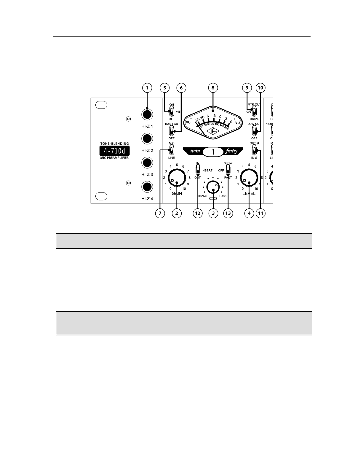
Front Panel Descriptions
Analog Controls
(1) Hi-Z Inputs - Connect a high impedance signal from an instrument such as electric guitar or bass
to these standard unbalanced 1/4" phone jack connectors. The 4-710d’s jack detection circuitry
automatically switches from the selected rear panel MIC or LINE input to the channel’s front panel Hi–
Z input whenever a plug is inserted into this jack. The Hi-Z input impedance is 2.2MΩ for all four
inputs. These JFET direct inputs provide maximum fidelity with no high-end loss.
(2) Gain - Adjusts the gain of the channel’s input stage. Turning this knob clockwise raises the
amount of gain applied to the input signal. This control also determines the level sent to the
compressor if the compression circuit ( #13 on page 11) is engaged.
(3) Blend (“∞”) - This unique control sets the relative contribution from the solid-state and vacuum
tube preamplifier circuits. When in the fully counterclockwise (TRANS) position, only signal from the
solid-state preamplifier is heard. When in the fully clockwise (TUBE) position, only the signal from the
tube preamplifier is heard. At the twelve o’clock position, signal from both the solid-state and tube
preamplifiers is heard at equal amounts.
Making a connection to the 4-710d’s front panel Hi-Z input jack automatically disconnects
any signal arriving at the rear panel mic and line input.
The controls for channels 1-4 are identical, so each control is only described once.
Page 10

Front Panel
10
(4) Level - This is the channel’s master volume control. It determines the amplitude of the signal sent
to the rear panel LINE OUTPUT ( #8 on page 16) and INSERT SEND ( #11 on page 16) jacks. This
control also sets the level sent to the A/D converter inputs.
(5) +48V - Most modern condenser microphones require +48 volts of phantom power to operate. When
in the up position, 48 volts of phantom power are available at the channel’s rear panel MIC INPUT.
(See page 21 for more information about phantom power)
(6) -15 dB PAD - When enabled (placed in the up position), the channel’s MIC INPUT signal will be
reduced by 15 dB (this switch has no effect on LINE INPUT or Hi-Z signal). Use the PAD to reduce the
incoming signal in cases where undesired distortion is present at low gain levels (for instance, where
especially sensitive microphones are used on loud instruments or if the A/D converter is clipping).
(7) Input Select - Determines whether the channel’s MIC (up position) or LINE (down position) input is
active. If the channel’s Hi-Z input is in use, this switch has no effect.
( See “Analog Connectors” on page 15 for more info on the rear panel inputs)
(8) Meter - This standard VU meter can display the channel’s overall output level, tube drive level, or
amount of compressor gain reduction. The function that is displayed depends upon the setting of the
Meter Function switch (#9 on page 11).
Keep phantom power off (switch down) when it is not required.
To avoid loud transients, always make sure phantom power is off when connecting or
disconnecting microphones.
Always check the power requirements of your microphone with the manufacturer before
applying phantom power.
The numeric values for the Gain and Level knobs are relative scale markings and do not
represent specific dB values.
! You can come up with many useful tonal variations by experimenting with different Gain
and Level settings.
Page 11

Front Panel
11
(9) Meter Function - This three-position switch determines what the channel’s VU meter displays. In
the up (OUTPUT) position, it shows the final output level in dB. "0" on the VU meter corresponds to +4
dBu at the analog outputs and -16 dBFS at the A/D converter inputs. In the down (DRIVE) position, it
shows the input level to the tube stage after the front panel Gain control, but before the Blend and
Level controls, thus giving an accurate gauge of how hard the tube and solid-state preamplifiers are
being driven. In the center (GR) position, the meter displays the amount of gain reduction occurring in
the channel’s compressor if the COMP switch (#13 below) is engaged for the channel. If the
channel’s compressor is off, the meter will not deflect from zero when set to GR.
When the switch is in DRIVE mode, the meter is calibrated so that 0 VU is equal to 1.2% THD on a 1kHz
sine wave. When OUTPUT is selected, a meter reading of 0 VU corresponds to a level of +4 dBu at the
rear panel LINE OUTPUT jack.
( See “Drive Metering” on page 25 for additional analog metering info)
(10) Low Cut - When enabled (placed in the up position), the channel’s input signal passes through a
75 Hz low cut filter. This is normally used to eliminate rumble and other unwanted low frequencies
from an incoming signal.
( See page 21 for more information about low cut filtering)
(11) Polarity (“ø”) - Determines the polarity of the channel’s LINE OUTPUT ( #8 on page 16) and
the polarity of the signal at the A/D converter inputs. When off (in the down, IN ø position), pin 2 of the
LINE OUTPUT is hot (positive). When the switch is enabled (in the up, OUT ø position), the output signal
is placed out of phase and pin 3 of its LINE OUTPUT is hot (positive). Normally the switch should be off
and only enabled when it is desirable to reverse the polarity, i.e., in cases where more than one
microphone is utilized in recording a source signal.
( See page 21 for more information about polarity inversion)
(12) Insert – When enabled (placed in the up position), the input signal is routed through the channel’s insert jacks on the rear panel ( “Insert Loop” on page 16) for external processing. When
disengaged (in the down position), the signal at the return jack is ignored. The insert switch allows you
to leave external processors conveniently connected when you don’t want to currently use them on the
channel.
(13) Comp – This three-position switch controls the channel’s 1176-style analog compressor. The
compressor has a compression ratio of 4:1 and the threshold is 10 dBu.
When in the up (FAST) position, the compressor attack time is 0.3 ms and the release time is 100 ms.
When in the down (SLOW) position, the attack time is 2.0 ms and the release time is 1100 ms.
If the METER FUNCTION switch (#9 above) is set to GR, the amount of compressor gain reduction is
displayed in the METER.
! The Send jack is active even when Insert is disengaged, so you can route the channel’s
signal to a monitor mix, tuner, etc.
Page 12
Front Panel
12
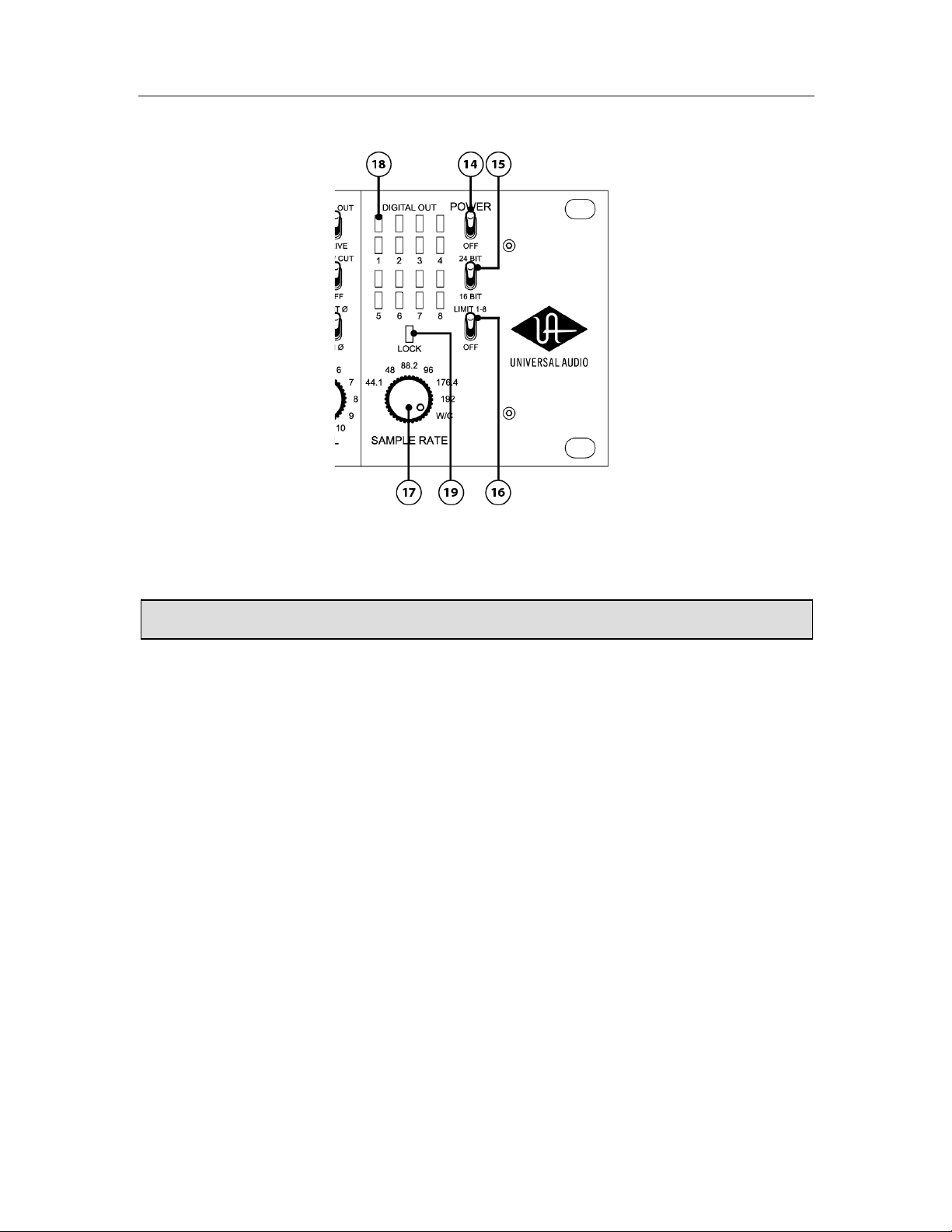
Digital Controls
(14) Power - Turns the 4-710d power on or off. When powered on, the front panel meters light up.
(15) Bit Depth – This switch determines the bit depth, or resolution, of the digital output signal for all
eight A/D channels. In the up position, the digital output word length is 24 bits; in the down position,
the digital output word length is 16 bits.
The actual A/D conversion of the 4-710d is always performed at a 24-bit word length. When the switch
is set to 16-bit mode, the 24-bit signal is triangular dithered to 16 bits.
(16) Limit 1-8 – This switch activates the built-in analog limiter for all eight inputs prior to A/D
conversion. The limiter is global for all eight inputs; it cannot be individually enabled per channel
(unlike the mic pre compressors on channels 1-4).
The limiter threshold is 17dBu (= -3dBFS) and the ratio is effectively infinite. The attack time is 0.075
ms and the release time is 100 ms. Although the limiter will help prevent “digital overs” (A/D clipping)
during conversion, it is not a “brick wall” limiter. It is still possible to clip the A/D input, especially
with very hot signal levels and/or signals with fast transient peaks.
(17) Sample Rate - This knob defines the internal sample rate of the A/D converter or selects external
clocking. The following sample rates are supported (kHz): 44.1, 48, 88.2, 96, 176.4, and 192.
When Sample Rate is set to W/C (external word clock) the 4-710d is a word clock slave and the
incoming clock rate at the rear panel’s BNC Word Clock In connector ( #2 on page 14) is used to
determine the sample rate for A/D conversion.
( For more details, please see the “Digital Clocking Primer” section on page 23)
The 4-710d should be powered off when it is not being used for extended periods of time.
Page 13

Front Panel
13
(18) Digital Out Level - These LEDs indicate the signal level of the A/D converters. Each of the eight
A/D channels has its own two-segment level indicator.
The lower LED illuminates green when the incoming signal is between -37 dBFS and -6 dBFS. This LED
displays the signal level continuously (it does not have peak/hold functionality).
The upper LED is a two-state indicator. When the incoming signal is between -6 dBFS and -1 dBFS, the
LED is yellow; the LED is red when the signal exceeds -1 dBFS. This LED has a peak/hold
implementation; signal peaks are “held” for 90 ms.
(19) Lock - When the 4-710d is locked (synchronized) to a clock source, the LOCK indicator glows
green. The indicator glows red when the clock is not locked. The clock is always locked when the
Sample Rate knob (#17 on page 12) is set to an internal sample rate. For the clock to be locked
when the clock source is external, a valid clock signal must be present at the rear panel word clock
input (see note above).
In order for the 4-710d to detect and lock to a valid external word clock, the frequency of
the incoming word clock must be within ±3% of any of the supported sample rates (44.1,
48, 88.2, 96, 176.4, or 192 kHz). If the frequency of the incoming work clock is not within
±3% of a supported sample rate, the LOCK indicator will glow red, the WORD CLOCK OUT
will be driven at 48 kHz, and the digital outputs will be driven at 48 kHz and muted.
The clock must be locked for proper A/D conversion.
If the clock won’t lock when the Sample Rate knob is set to W/C (external word clock),
verify that the external device is connected to the word clock BNC input and is transmitting
a valid clock signal.
The 4-710d cannot lock to an external device that is set to slave to the 4-710d!
Page 14

14
Rear Panel Descriptions
Digital Connectors
(1) AES/EBU Out – All eight channels of the 4-710d’s A/D converters are output in AES/EBU digital
format on this standard DB-25 connector. The 4-710d AES/EBU output supports “Single Wire” mode at
all available 4-710d sample rates. The AES/EBU output does not support “Dual Wire” mode at sample
rates above 96 kHz.
( The DB-25 connector pin-out assignments are detailed in Maintenance on page 34)
(2) Word Clock In – The 4-710d’s internal clock can be synchronized (slaved) to an external master
clock. This is accomplished by setting Sample Rate knob ( page 12) to “W/C,” connecting the
external word clock’s BNC connector to the Word Clock “In” port, and setting the external device to
transmit word clock.
The frequency of the incoming word clock must be within ±3% of any of the supported sample rates. If
not, the LOCK indicator will glow red, the word clock OUT will be driven at 48 kHz, and the digital
outputs will be driven at 48 kHz and muted.
External clocking is required when connecting the 4-710d to another digital device, such as a computer audio interface, whose digital clock is set to internal (making that device the “master” clock). All
digital devices in a system should be “slaved” to the master clock, otherwise clicks and/or pops could
be encountered when recording or monitoring the digital audio stream from the 4-710d.
( For more details, please see the “Digital Clocking Primer” section on page 23)
Digidesign’s 192 I/O supports AES/EBU at sample rates above 96 kHz only in Dual Wire
mode. Therefore the 4-710d is incompatible with the 192 I/O when connected via AES/EBU
at sample rates of 176.4 kHz and higher.
The 4-710d can be synchronized to an external “1x” clock signal only. Superclock,
overclocking, and subclocking are not supported.
Page 15

Rear Panel
15
(3) Word Clock Out – This BNC connector transmits a standard (1x) word clock. For all settings except
W/C, the 4-710d is the clock master and the clock rate sent by this port is specified by the Sample
Rate knob (#17 page 12). The 4-710d will drive the Word Clock to all devices on the chain.
When the Sample Rate is set to W/C (external word clock), the 4-710d is a word clock slave. If the
incoming external word clock is within ±3% of a supported sample rate (44.1 kHz, 48 kHz, 88.2 kHz,
96 kHz, 176.4 kHz, 192 kHz), Word Clock Out will mirror Word Clock In with a slight phase delay (about
40ns). If the incoming external word clock is not within ±3% of a supported sample rate, Word Clock
Out will default to 48kHz, and the digital outputs will be muted.
Word Clock Out does not truly mirror Word Clock In, so Word Clock Out should not be used to daisy
chain the Word Clock if the 4-710d is in the middle of the Word Clock chain. The correct method to
connect the 4-710d in the middle of a Word Clock chain is to use a T-connector at the 4-710d Word
Clock input, and leave the 4-710d Word Clock Out unconnected.
( For more details, please see the “Digital Clocking Primer” section on page 23)
(4) 75Ω Termination – This pushbutton switch provides internal word clock termination when
required. Termination is active when the switch is engaged (depressed).
Word clock termination should only be used at the receiving end of a word clock cable, or, if the cable
is daisy-chained across several units, termination should only be used on the last unit in the chain.
For example, if the 4-710d is the last “slave” unit at the end of a clock chain (when the
4-710d’s word clock “Out” port is not used), termination should be active. If the word clock is passed
through the 4-710d to another unit (when the 4-710d’s Word Clock Out port is connected, passing the
word clock through to another device), termination should be disabled.
(5) ADAT Optical Outputs 1 & 2 – Up to eight channels of the 4-710d’s A/D converters are output in
ADAT optical format using these two connectors. The particular 4-710d channels that are output at
each port depend upon the current sample rate setting. At sample rates of 44.1kHz and 48kHz, all
eight channels are output on both ADAT ports (mirrored). At higher sample rates, industry standard
S/MUX™ multiplexing is used to maintain high-resolution transfers. At rates of 88.2kHz and 96kHz,
channels 1-4 are output on ADAT port 1, while channels 5-8 are output on port 2. At 176.4kHz and
192kHz, channels 1 and 2 are output on port 1, while channels 3 and 4 are output on port 2 (channels
5-8 cannot be output via ADAT optical at the highest rates). These correlating values are shown in the
following table:
Analog Connectors
(6) AC Power Input – Connect a standard, detachable IEC power cable (supplied) here.
(7) Line Inputs 5 through 8 – These four line inputs feed directly into channels 5–8 of the 4-710d’s
A/D converters. Any ¼” phone plug (balanced TRS or unbalanced TS) carrying a line-level signal can
be connected here for output via the AES/EBU or ADAT digital outputs. These inputs are fed into the
limiter when the limiter (#16 on page 12) is enabled.
Sample Rate
Knob Setting:
ADAT Port 1
Output channels:
ADAT Port 2
Output channels:
44.1, 48
1-8
1-8 (mirrored)
88.2, 96
1-4
5-8
176.4, 192
1-2
3-4
Page 16

Rear Panel
16
Two 4-710d units can combined using these inputs to obtain eight mic pre channels on one 8-channel
digital stream. Simply connect the channel 1–4 line outputs of the first unit to the line inputs 5–8 of
the second unit; the digital outputs of the second unit will now contain the combined mic pres of both
units!
Note: There are no analog outputs for line inputs 5–8.
(8) Line Output - A balanced XLR connector that carries the line-level output signal of the 4-710d
channel. Note that Pin 2 is positive when the front panel Polarity switch ( #11 on page 11) is off (IN
ø). Pin 3 is positive when the front panel Polarity switch is engaged (OUT ø).
(9) Line Input - Connect any line-level input signal (coming from a device such as a mixer, DAW, tape
machine, or signal processor) into this balanced XLR connector. Pin 2 is wired positive (hot).
Any ¼” phone plug line-level output can also be connected to the Insert Return jack ( #12 below),
and if the Insert switch for the channel ( #12 on page 11) is engaged, that signal will be used for
the channel input instead of the XLR line input.
(10) Mic Input - Connect a microphone to this standard XLR connector. Pin 2 is wired positive (hot).
+48V phantom power is available via the front panel switch.
Insert Loop - An external audio processor (for example, EQ or compressor) can be inserted into the
analog path of channels 1-4 using the Insert Loop for additional processing of the channel’s signal
using the Send and Return jacks (#11 and #12 below). The Insert Loop can be enabled or disabled
using the Insert switch for the channel on the front panel ( #12 on page 11).
(11) Insert Send – Connect this jack to the audio input of the external processor. The signal at this
jack is post-preamp, so all level and sonic changes made with the associated channel’s front panel
controls will be reflected here. The jack is “half-normalled” which means you can extract the channel’s
signal from here even if you don’t use the associated Insert Return. This is handy for routing the signal
to a monitor mix, tuner, etc.
The signal at the Insert Send jack is identical to the signal at the XLR Line Output jack. Both channel
outputs can be used simultaneously without any signal loading issues.
(12) Insert Return– Connect this jack to the audio output of the external processor. The signal at this
jack is only audible if the associated channel’s Insert switch on the front panel ( #12 on page 11) is
engaged.
The Insert Return jack can be used as a ¼” line input for the channel in lieu of the XLR input. The
Insert Return is used as the input when the channel’s Insert switch ( #12 on page 11) is engaged.
Since the connectors for channels 1–4 are identical, each is only described once below.
All Insert connections accept standard ¼” male phone plugs. Balanced TRS and
unbalanced TS connectors can be used.
Page 17

17
Interconnection Diagrams
Analog-Only Setup
This diagram illustrates a typical system using the 4-710d in an analog-only configuration, such as
when using it as the front end to a public address system or analog recording device. In this setup, the
digital features of the 4-710d are not used.
The example shows a microphone connected to channel 1, a keyboard connected to the insert return of
channel 2 (to use the ¼” line input instead the XLR line input), and a guitar connected to channel 3
using the Hi-Z input. A signal processor (e.g., reverb) is connected via the insert loop of channel 1 for
the mic. The insert send of channel 3 (but not the return) is used as a guitar direct output for
connection to a tuner. The line outputs are connected to an analog mixer where the input signals are
combined before being sent to powered PA speakers.
Key points for this example:
• Mic/Line switch for channel 1 is set to “Mic”
• Insert switches for channels 1 and 2 are set to “In”
• Line outputs are connected to an analog mixer for monitoring
Page 18

Interconnections
18
Basic Digital Setup
This diagram illustrates a typical system using the 4-710d as the front end of a digital recording
setup. A variety of input sources are used, with the 4-710d performing A/D conversion on the inputs. In
this setup, the converted input signals are sent to the computer digitally via the ADAT lightpipe, and
the software monitoring features of the DAW are used to monitor the 4-710d inputs.
The example shows microphones connected to channels 1 and 2, guitar and electric bass connected to
the H-Z inputs of channels 3 and 4, and a stereo keyboard connected to line inputs 5 and 6. A guitar
effects processor is connected via the insert loop of channel 3. The insert send of channel 4 (but not
the return) is used as a bass direct output for connection to a tuner. The ADAT output from the 4-710d
is connected to the ADAT input of the computer’s audio interface for monitoring and recording.
Key points for this example:
• Mic/Line switch for channels 1 and 2 are set to “Mic”
• Insert switch for channel 3 is set to “In”
• ADAT output is connected to computer audio interface
• Internal clock is used (Sample Rate knob is NOT set to “W/C”)
• Computer is set to synchronize (“slave”) to ADAT external clock
• Computer DAW is used for software monitoring
Page 19

Interconnections
19
Advanced Digital Setup
This diagram illustrates a typical system using the 4-710d as the front end of a more complicated
digital recording setup. A variety of input sources are used, with the 4-710d performing A/D conversion
on the inputs while slaved to an external word clock. In this setup, the converted input signals are sent
to the computer digitally via the AES/EBU output, and the software monitoring features of the DAW are
used to monitor the 4-710d inputs.
(See the “Digital Clocking Primer” on page 23 for detailed info about synchronization)
The inputs and inserts are connected as in the previous example. The AES/EBU output from the 4-710d
is connected to the AES/EBU DB-25 input of the computer’s audio interface, and the word clock output
is connected from the audio interface to the 4-710d word clock input. The software monitoring features
of the DAW are used to monitor the 4-710d inputs.
Key points for this example:
• Mic/Line switch for channels 1 and 2 are set to “Mic”
• Insert switch for channel 3 is set to “In”
• AES/EBU output is connected to computer audio interface
• Word clock out from audio interface is connected to 4-710d word clock input
• Sample Rate knob is set to “W/C” (external clock synchronization is used)
• Computer DAW is used for software monitoring
Page 20

20
Model 4-710d Overview
The Universal Audio 4-710d, with its four mic preamps derived from our TEC award-winning UA Model
710 Twin-Finity Mic/Line/Hi-Z Preamplifier, combines our highly revered analog tube and solid state
preamplification technology... but with a twist. Its unique phase-aligned Blend controls allow the user
to literally dial in the desired sound, from precise ultra-clean solid-state tones to fat tube presence
and overdriven crunch, or anywhere in between. Additionally, each of the four mic preamp channels
has an 1176-style analog compressor that can be individually enabled for each channel.
Other features include JFET Direct Inject inputs (which allows for the direct connection of an electric
guitar or bass, or any instrument with a magnetic or acoustic transducer pickup); monolithic balanced
output stages; +69 dB of gain; +48V power and a -15 dB pad for the mic inputs; polarity inverts and
75 Hz low cut filters; output and “Drive” (input) VU metering; a universal auto-sensing internal power
supply that allows for operation at any voltage between 100 and 240VAC; and a 2U, rack-mountable
design for studio or stage.
4-710d Vacuum Tube Preamp
The 4-710d high voltage (285 VDC) Class-A tube preamp section is based upon both classic guitar
amplifier design and classic tube mic preamp design. The circuit utilizes a 12AX7 tube for warmth and
roundness and is the second gain stage, located downstream from the Gain control pot. This allows
the circuitry to be overdriven by the first stage into anything from mild harmonic distortion to all-out
grunge; however, the transition to tube saturation is extremely gentle. The result is the gradual onset
of harmonic overdrive—no hard clipping here. As an example, the transition from 1% THD to 4% THD
occurs over a 14 dB range. Because of its multiple gain stages, with a Gain control pot between them
(as well as a Drive Meter that displays the signal level entering the second stage), a wide variety of
tonal possibilities can be dialed in, from gentle warmth to extreme grit.
4-710d Solid-State Preamp
The 4-710d solid-state preamp circuitry utilizes Universal Audio’s transimpedance design for precision
sound and ultra-low distortion, delivering the highest possible quality of signal from input to output.
The term “transimpedance” refers to transistor configurations that employ current feedback to provide
gain and distortion immunity without the loss of sonic detail or musicality. Designed for applications
requiring the ultimate in transparent amplification with little or no coloration, its razor flat and
immensely wide frequency response yields highly accurate results and minimizes artifacts on the way
to the recording medium.
Noise and distortion are kept to near-theoretical minimums so critical signals may be generously
amplified without degrading the quality or character of the sound source. Zero-coloration preamps
such as these are especially useful for capturing the sound source with its original qualities and
character so that later processing may occur with maximum flexibility. There are no transformers or
tubes in the preamp signal path, and the 1176-style compressor/limiter (located after the
preamplifier) can be switched out as desired to eliminate permanent audio coloration. For many users,
the useful characteristics of these devices are preferred at the mix stage—and are commonly
implemented using DSP processors and plug-ins with excellent (and reversible) results, such as those
found on Universal Audio’s UAD plug-in platform.
About “Class A”
Most electronic devices can be designed in such a way as to minimize a particularly unpleasant form
of distortion called crossover distortion. However, the active components in “Class A” electronic
devices such as the 4-710d draw current and work throughout the full signal cycle, thus eliminating
crossover distortion altogether.
Page 21

Model 4-710d Overview
21
Phantom Power
Most modern condenser microphones require +48 volts of DC (Direct Current) power to operate. When
delivered over a standard microphone cable (as opposed to coming from a dedicated power supply),
this is known as “phantom” power. The 4-710d provides such power when the Phantom switch (
page 11) is engaged (placed in the +48V, up position), applying 48 volts to pins 2 and 3 of the rear
panel output connector.
While, in theory, this should result in no harm to the connected microphone even if it does not require
phantom power, problems can occur if the shield (pin 1) is broken or when using inexpensive
microphones that use the shield as their ground. The application of phantom power can even damage
those older ribbon microphones that have their output transformers wired with a grounded center-tap.
What’s more, the application of phantom power can often result in a loud pop (transient). For these
reasons, we strongly recommend that the Phantom switch be left in its off (down) position when
connecting and disconnecting microphones. Only turn the Phantom switch on if you are certain that
the connected microphone requires 48 volts of phantom power. If in doubt, consult the
manufacturer’s owner’s manual for that microphone.
Polarity Inversion
The occasional need for polarity inversion (changing the 4-710d front panel switch from IN ø to OUT ø)
is best demonstrated by a common example: recording an open-backed guitar amplifier with two
microphones, where one mic is placed close to the front of the amp's speaker and the other near the
back of the amp. The waveform display of the first mic will show an upward peak when the speaker
pushes outward, placing positive sound pressure on the mic. However, the waveform display of the
second mic (the one behind the amp) will show a downward (negative) valley when the speaker pushes
forward, because from the back of the amp the speaker moves away from the mic, thus creating
negative sound pressure. If these two signals are mixed, the positive waveform from the front mic
combines with the negative waveform from the back mic to result in cancellation of much of the amp's
sound and a "thinning effect" that is sonically disappointing. However, if the phase of one of the mic
signals is inverted, the two signals will combine instead of cancelling, and the result will be much
fuller and sonically pleasing.
Other double-mic applications often requiring phase inversion include piano soundboards, drum heads
(one mic on top of the drum and the other below it), and acoustic guitar miking, where one mic is
placed close to the soundhole and another further away or behind the guitar.
Low Cut Filtering
A common method for optimizing mixes is to apply low-cut filtering whenever possible. Excessive low
frequencies from microphones and instruments tend to build up in the mix, creating sonic “mud” that
masks musical detail, overloads or fatigues the listener’s ears, and sucks energy from power amps
and speakers. It isn’t uncommon to notice meters showing noticeably lower levels after low-cut
filtering is applied—a sure sign that such filtering was necessary. In addition, after low-frequency
mud is filtered, there is often more room in the mix to bring up important musical elements such as
vocals and lead instruments, resulting in a win-win situation (less mud = more music).
Typically, a low cut filter can be used to remove: vocal "B","P" and other popping sounds; moving-air
noise from close-miked vocals, drums, guitars and outdoor weather; instrument body noise from
handling guitars, basses, pianos, saxophones, etc; mic-stand vibrations; studio or stage floor
vibrations; air-conditioning; electrical hum; and unwanted proximity-effect bass boost.
Page 22

Model 4-710d Overview
22
A/D Conversion
The 4-710d conveniently provides eight channels of high-quality analog to digital (A/D) conversion
with digital output via AES/EBU DB-25 and ADAT optical connectors. No matter what task you give it,
the 4-710d can dramatically improve the quality of your audio environment. The 4-710d provides up to
eight channels of sterling sound quality for tracking, monitoring and mastering, with full support for
today’s higher sample rates of 88.2, 96, 176.4, and 192kHz. These capabilities make the 4-710d an
excellent front end for any digital audio workstation. The 4-710d delivers superb audio fidelity thanks
to its pristine Class-A analog signal path.
AES/EBU Digital Output
All eight channels of the 4-710d’s A/D converters are output in AES/EBU digital format on an industrystandard DB-25 connector. The 4-710d AES/EBU output supports “Single Wire” mode at all available
4-710d sample rates (the AES/EBU output does not support “Dual Wire” mode at sample rates above
96 kHz).
ADAT Optical Digital Output
The 4-710d provides two standard ADAT optical digital output ports. At sample rates of 44.1kHz and
48kHz, all eight channels are output on both ADAT ports. At higher sample rates, industry standard
S/MUX™ multiplexing is used to maintain high-resolution transfers.
Word Clock I/O
Word clock input and output is provided for synchronizing (slaving) with external hardware devices.
Connections are via standard 75-ohm BNC connectors. Switchable 75-ohm termination is available.
Digital Metering
Digital output level metering for A/D conversion is provided by eight 2–segment LED displays. Each
channel has its own output indicator.
(Digital meter behavior is described in #18 on page 13)
Page 23

23
Digital Clocking Primer
Digital clocking is a complicated issue, with a number of important aspects that are often not very
well understood.
First and foremost, a digital clock is used to maintain synchronization between different digital
devices. There are two primary purposes for clock synchronization:
1. Digital Conversion. Analog-to-digital (A/D) conversion and digital-to-analog (D/A) conversion need
extremely accurate clocking in order to correctly process the digital data. A low-quality clock can
degrade the signal in many ways, including loss of transparency, clarity, imaging and transient
response, as well as increased noise and distortion.
2. Digital Transmission. All digital devices need accurate clocking in order to properly transfer digital
data between interconnected devices. A low-quality clock can cause data reception errors, which
add distortion and noise, and if the clock isn’t synchronized correctly, samples may be dropped or
repeated, resulting in audible clicks or dropouts.
Clock quality is defined two ways: First, the sample rate must match the signal. This is referred to as
“sample rate synchronization.” Second, the clock signal must be stable over both short- and long-term
clocking intervals. “Jitter” refers to short-term clock accuracy, and “stability” or “drift” refers to longterm clock accuracy. These terms are discussed in more detail below.
Sample rate synchronization is required for proper digital transmission, and is relatively easy to
maintain. Basically, there must be one and only one “clock master” for all interconnected digital
devices. This is done by setting one device to “master” mode (where it synchronizes to its internal
clock and transmits that clock signal) and setting every other device to “slave” mode (where it
receives and synchronizes to external clock), with the appropriate clock signal routed between the
master and slave devices. Keep in mind that any device, whether it’s the clock master or a slave, can
send or receive data once everything is synchronized correctly.
When doing digital conversion, it’s best to have the converter serve as the clock master. For example, if
you’re recording, clock everything off the A/D converter. Likewise, if you’re mixing, clock everything off
the D/A converter. If you’re running multiple converters, use the device with the best quality clock as
master.
For all-digital transfers, e.g., a digital transfer from one DAW or storage device to another, clock
synchronization is maintained by simply setting up the proper master-slave relationship between
devices. Digital transfers can be affected by clock jitter, but not in the same way clock jitter affects
analog conversion. This is a widely misunderstood concept we’ll discuss in detail below.
Clock jitter is short-term variations in the edges of a clock signal, as opposed to clock drift, which is
long-term variations in the clock rate. A clock could be very stable over the long term, but still have
jitter, and vice versa. Timing variations are caused by noise and/or interference. If the
noise/interference is a high-frequency signal, the result is jitter, and if the noise/interference is a lowfrequency signal, the result is drift. As an analogy, a car with an out of balance wheel may drive
straight, but you’ll get lots of vibration (jitter); conversely, a car with a loose steering wheel might
have a smooth ride, but it will drift all over the road.
Clock drift affects long-term synchronization, like sound to picture, and can introduce slight pitch
variations in the audio. Usually however, the drift is so slow that these pitch variations are only tiny
fractions of a cent, and thus unnoticeable.
Page 24

Digital Clocking Primer
24
Clock jitter affects digital transmission and digital conversion differently, as follows:
• Clock jitter in digital transmission can be caused by a bad source clock, inferior cabling or
improper cable termination, and/or signal-induced noise (called “pattern-jitter” or “symbol-jitter.”)
Digital signal formats like AES/EBU, S/PDIF, and ADAT all embed a clock in the digital signal so the
receiving device can synchronize to the transmitted data bits correctly. The clock used for data
recovery is extracted from the signal using a clock synchronization circuit called a phase-lockedloop (PLL). This data-recovery PLL must be designed to respond very quickly to attenuate highfrequency jitter and avoid bit errors during reception. This clock from the data-recovery PLL cannot
be used to generate the clocks used for digital conversion without further clock conditioning! This
is a very common design flaw in most low- and mid-range digital converters.
• Clock jitter in digital conversion is what most people refer to when they discuss jitter. It’s easily
observed in a digital signal by looking at its spectrum in the frequency domain. A jittery signal will
have “side-lobes” around each frequency and/or spurious tones at random, inharmonic
frequencies. Usually, the jitter will be worse with higher signal frequencies. You can test your
converters by sampling a high-quality 10kHz sine wave, and viewing it in the frequency domain
(available with any good wave editing software package).
All modern over-sampling digital converters require a clock (called “m-clock”) that is many times
(typically several MHz) higher than the sample clock. M-clock is easy to generate when the converter is
the clock master, but quite difficult to generate correctly when the converter needs to sync to an
external clock.
External clock typically comes from a dedicated word clock input, or is extracted from the incoming
digital AES/EBU, S/PDIF or ADAT signal. Word clock cannot be used by the converters until it is
multiplied up to the m-clock rate. This requires a PLL or other frequency multiplier circuit which will
either be cheap and jittery, or expensive and clean, depending on who makes the converter. As we said
earlier, the clock recovered from the digital inputs is unsuitable for use as the converter’s m-clock, but
because it’s conveniently at the same frequency, many designers don’t bother cleaning up this signal.
Since the clock recovery, clock multiplier, and clock conditioning circuitry define the jitter for analog
conversion, no external clock source can clean up the jitter introduced by these circuits, regardless of
how perfect the external source clock is. The best they can do is avoid making it any worse, but this is
hardly worth the cost: It’s much better (and less expensive) to get a good converter than it is to try and
fix a bad one with an expensive master clock. The only reason to spend money on a high-quality master
clock is to ensure that multiple devices are synchronized correctly. This is essential for working with
audio for film/video, or when synchronizing multiple high-quality converters. A poor master clock can
also affect imaging and clarity in a multi-track environment.
The 4-710d provides high-quality analog to digital conversion for recording and/or playback. With its
pristine audio path, high-quality clocking, and simple front panel controls, it makes a great master or
slave audio interface for every digital studio, and thus provides a very cost effective way to improve
overall sound quality.
In order for the 4-710d to detect and lock to a valid external word clock, the frequency of
the incoming word clock must be within ±3% of any of the supported sample rates (44.1,
48, 88.2, 96, 176.4, or 192 kHz). If the frequency of the incoming work clock is not within
±3% of a supported sample rate, the LOCK indicator will glow red, the WORD CLOCK OUT
will be driven at 48 kHz, and the digital outputs will be driven at 48 kHz and muted.
Page 25

25
Insider’s Secrets
The Best of Both Worlds
There’s a reason why tube preamplifiers have long been favored by audio engineers (especially in this
age of digital recording): they impart a warmth and richness that makes most sounds larger than life.
However, there is no denying that tube preamps also tend to color the incoming signal somewhat,
albeit in a way which most listeners find pleasant and desirable.
On the other hand, the recording of voice and acoustic instruments sometimes requires precise signal
handling with meticulous attention to detail, definition and accuracy. Applications such as classical or
jazz recording demand faithful transfer of performances exactly as they happen, without coloration,
processing, noise or distortion, and that is where solid-state preamplifiers shine. Plus, by capturing
the sound as it is, you can leave sound sculpting and “coloration” decisions until later, during the
mixing stage.
So the question is, which kind of preamp to use? Up until now, the only solution has been to have an
arsenal of both kinds at your disposal, but with the 4-710d, that’s no longer necessary, since it
provides both designs in one box, as well as a unique Blend control that allows the user to dial in the
precise contribution of each preamp to the overall sound. As a good starting point, we recommend that
you set the Blend control to the desired degree of tube coloration, then back it off slightly (towards the
TRANS position) to dial in the precise amount of “snap” and detail you want in your sound.
Drive Metering
Because it shares lineage with vintage guitar amplifier designs, the 4-710d’s tube preamplifier can
contribute precise amounts of even-order harmonic distortion (the kind the ear enjoys listening to) to
your signal, ranging from pleasant amounts of rasp to all-out grunge. The Drive meter function can be
a great tool in helping to decide how high to raise the Gain control because it indicates how much tube
saturation is going to be present in the output signal. It does this by monitoring the signal that is
driving the tube. If what you want is crystal clear tube tone, then the meter will be bouncing around
near the low end of its range. If what you are after is a ton of tube dirt, then drive the meter into the
red; there is nothing wrong with either extreme. Once you use the Drive function a few times, you will
develop a feel for it, and should be able to dial in the desired tube character quickly and easily.
When in Drive mode, the 4-710d meter is calibrated so that 0VU is equal to 1.2% THD on a 1KHz sine
wave. However, measured distortion levels can be misleading because they are so source and style
dependent. 2% THD on a sine wave is a fair amount of distortion and will be apparent to even the nonmusically inclined. On a vocal track, however, that same 2% THD sounds like some really nice tube
warmth. On an overdriven guitar, 2% is barely even audible. The most important thing to remember
when using the Drive function is that there is no “wrong” meter reading, only wrong tones for a
particular track. So use the meter as guide, not as a pass/fail test. Do what feels and sounds right,
and don’t be afraid to push it.
Vocals, Vocals, Vocals
Just as certain microphones work best with certain vocalists, so too do certain mic preamps. The
presence of not just one, but two completely discrete preamps in the 4-710d mean that it will work
wonders with just about any microphone... and with just about any vocalist.
The crisp precision of a condenser microphone, for example, can be matched perfectly by the uncolored
accuracy of the 4-710d’s transimpedance solid-state preamp... or you can instead opt to use the tube
side to “warm up” the tone. Better yet, use the Blend control to dial in exactly the right amount of both
preamps to match both the microphone’s frequency characteristics and the timbral quality of the
vocalist. And if you’re using the already warm sound of a tube microphone for vocals, try
Page 26

Insider’s Secrets
26
complementing it with the 4-710d’s solid-state preamp (or use the Blend control to dial in a
combination of the two that favors the contribution of the TRANS side).
Electric Guitar and Bass
There’s something very special about the mix of tube preamplification and electric guitar and bass,
which is why tube amps are so prevalent in that world. Cranking up the 4-710d's Gain control will
impart anything from a slight bark to total grunge. Set the Blend control all the way to TRANS for that
overloaded console effect, or all the way to TUBE to emulate the grittiness and bite of an overdriven
guitar amp... or anywhere in-between for a custom guitar sound perfectly crafted to the context of the
song.
Electric bass players may want to set the Blend control so that the solid-state amp is slightly favored
(try a 10 o’clock position to start), allowing you to take advantage of the precision of the
transimpedance preamp stage, combined with just a touch of tube warmth. For acoustic bass, try
dialing in just a touch more tube preamp.
Acoustic Guitar
The 4-710d is also a powerful tool for the recording of acoustic guitar. Try pairing it with a smalldiaphragm omnidirectional mic and then set the Blend to about the 2 o’clock position (thus slightly
favoring the tube preamp) for a sound that is both pristine and warm.
Horns and Reeds
The incredible detail provided by the 4-710d’s solid-state transimpedance preamp make it a perfect
match for horn and reed instruments. Dial in just a touch of the tube preamp (set the Blend control to
approximately 9 o’clock) to add a touch of tube warmth, and you’ve got a sound that will work in just
about any musical context.
Drums
The huge range of sonic possibilities offered by the 4-710d make it an invaluable companion for any
kind of drum miking. The excellent transient response of its solid-state transimpedance preamp serves
to enhance overhead and ambient mics picking up the crispness of cymbals, while the roundness of its
tube preamp adds fullness to snare and tom mics. Again, the best solution is usually a blend of the
two, depending upon the specific mics being used and the mic positioning. Be sure also to experiment
with the 4-710d polarity control whenever multiple mics are being used!
Improving the Sound of Your Microphone
Incredible but true: in some cases, the 4-710d can make an inexpensive microphone sound like an
expensive one. Even an inexpensive stage dynamic microphone can come to life when routed through
one or both 4-710d preamps, adding richness and airiness to the sound without adding undesirable
graininess or coloration.
Live Applications
Although the 4-710d was designed primarily for use in recording, it can also serve as a powerful
addition to a live sound rig, especially in FOH (Front Of House) applications. Because its tube preamp
section is based on vintage guitar amp design, it can even be used as an onstage preamp; just plug
your instrument directly into its Hi-Z input and then route the 4-710d output to a power amp and/or
FOH console input.
Page 27

27
History of the Model 4-710d
Like the microphone, preamplifiers come in all shapes, sizes and colors. And, like a microphone, the
preamp is one of many devices that may impart a sound to a recording... or may conversely attempt to
avoid coloration. In this way, mics and preamps can be compared to the various paints, brushes and
surfaces a visual artist may choose from, or to the various films, lenses and filters the photographer
uses in his process. In the same way that a photographer might choose a certain filter to reject a
certain type of light, a recording engineer may do the same with a mic to tailor out a certain frequency
range. The photographer may choose a particular film to convey a certain atmosphere, and a recordist
might choose a particular preamp for the very same reason. The critical decision is whether or not the
given device imparts the correct character (or lack thereof) for a given recording. The best thing about
choosing the right mic and preamp for the job is that when the session is going great and the music is
truly happening, the quality, character and nuanced detail of the engineer’s tools really begin to shine.
Because it is the component which transforms the very low-level signal from a microphone into a
useable signal—a critical transition of energy—the quality of the preamplifier plays a huge role in
shaping the final signal. And ultimately, a great mic preamp is all about great design.
Throughout the half-century or so of modern recording technology, a number of preamp designs have
been introduced, all with their own strengths and weaknesses. Early preamplifiers relied on vacuum
tubes to boost signal. One of the most popular preamps of the era was the one inside the 610 console
built by Bill Putnam Sr. in 1960 for his United Recording facility in Hollywood. As was the case with
most of Putnam’s innovations, the 610 was the pragmatic solution for a recurring problem in the
studios of the era: how to fix a console without interrupting a session. The traditional console of the
time was a one-piece control surface with all components connected via patch cords. If a problem
occurred, the session came to a halt while the console was dismantled. Putnam’s answer was to build
a mic-pre with gain control, echo send and adjustable EQ on a single modular chassis, using a printed
circuit board. Though modular consoles are commonplace today, the 610 was quite a breakthrough at
the time.
While the 610 was designed for practical reasons, it was its sound that made it popular with the
recording artists who frequented Putnam’s studios in the 1960s. The unique character of its microphone preamplifier in particular made it a favorite of legendary engineers like Bruce Botnick, Bones
Howe, Lee Hershberg, and Bruce Swedien, who has described the character of the preamp as “clear
and open” and “very musical.” The 610 console was used in hundreds of studio sessions for internationally renowned artists such as Frank Sinatra, Ray Charles, Sarah Vaughan, the Mamas and Papas,
the Fifth Dimension, Herb Alpert, and Sergio Mendes. The Beach Boys’ milestone Pet Sounds album
was also recorded using a 610.
But by the mid 1960’s, tiny solid-state components called transistors, followed by advanced technological innovations such as FETs (Field Effect Transistors), op amps (operational amplifiers), and ICs
(Integrated Circuits), had become ubiquitous and inexpensive to manufacture. These all did the job of
vacuum tubes, but with greater efficiency and reliability, less heat, much smaller size, and much
longer lifetimes. For these reasons, audio circuit designers such as Bill Putnam began creating preamplifiers using transistors instead of tubes. One of the first of these was the Universal Audio 1108.
This was an exquisitely designed, widely used single-stage modular preamp made for modular recording consoles. It featured input and output transformers, with connections for modular equalizers
such as the UA 508 EQ. This amp design became the basis for the enormously popular 1176 limiter,
which utilized the same output transformer. Interestingly, the 1108 has probably been used on many
more classic recordings than the 610, due to its broad popularity.
Page 28

History of the Model 4-710d
28
Throughout the years, solid-state preamplifiers have evolved into ever more sophisticated designs
(such as the Precision mic preamp utilized in the Universal Audio SOLO/110 and multichannel
4110/8110, and the transimpedance design first unveiled in the Universal Audio DCS Remote Preamp).
Until fairly recently, solid-state models were the norm in recording studios, but somewhere around the
explosion of digital recording, tube preamps suddenly became fashionable again, serving for some as
the antidote to so-called “cold” DAWs. Despite the fact that technology has vastly improved the quality
of even the least expensive converters and that higher sample rates and bit rates are commonly being
used, many still find something unforgiving about the medium. But there is more than one way to skin
the digital cat, and nowadays engineers reach for those tools that inject the correct character back
into what some call an overly critical medium.
The key is knowing which tools to reach for... and, in the case of preamplifiers, whether to opt for the
“warmth” of tubes or the precision of solid-state. The Universal Audio 4-710d allows the recordist to
literally enjoy the best of both worlds. Not only does it combine two preamplifiers per channel—one
vacuum tube and one solid-state—in a single box, its unique Blend control allows the engineer to dial
in precisely the desired amount of tone from each. The 4-710d is truly a cutting-edge product for its
time.
In 2000, Bill Putnam Sr. was awarded a Technical Grammy for his multiple contributions to the recording industry. Highly regarded as a recording engineer, studio designer/operator and inventor, Putnam
was considered a favorite of musical icons Frank Sinatra, Nat King Cole, Ray Charles, Duke Ellington,
Ella Fitzgerald and many, many more. The studios he designed and operated were known for their
sound and his innovations were a reflection of his desire to continually push the envelope. Universal
Recording in Chicago, as well as Ocean Way and Cello Studios (now EASTWEST) in Los Angeles all
preserve elements of his room designs.
The companies that Putnam started—Universal Audio, Studio Electronics, and UREI—built products
that are still in regular use decades after their development. In 1999, his sons Bill Jr. and James
Putnam re-launched Universal Audio and merged with Kind of Loud technologies—a leading audio
software company—with two goals in mind: to reproduce classic analog recording equipment
designed by their father and his colleagues, and to design new recording tools in the spirit of vintage
analog technology. Today Universal Audio is fulfilling that goal, bridging the worlds of vintage analog
and DSP technology in a creative atmosphere where musicians, audio engineers, analog designers and
DSP engineers intermingle and exchange ideas. Every project taken on by the UA team is driven by its
historical roots and a desire to wed classic analog technology with the demands of the modern digital
studio.
Page 29

29
Glossary of Terms
A/D - An acronym for “Analog to Digital,” which refers to the conversion of analog signal to digital.
ADAT - An acronym for “Alesis Digital Audio Tape.” ADAT was the name given to the Alesis-branded
products of the 1990s which recorded eight tracks of digital audio on a standard S-VHS video
cassette. The term now generally refers to the 8-channel optical connection that is used in a wide
range of digital products from many manufacturers.
AES - (sometimes written as “AES/EBU”) The name of a digital audio transfer standard jointly
developed by the American-based Audio Engineering Society and the European Broadcast Union.
Designed to carry two channels of 16-, 20- or, 24-bit digital audio at sampling rates of up to 192kHz,
the most common AES physical interconnect utilizes a 3-conductor 110 ohm twisted pair cable,
terminating at standard XLR connectors. (See “Dual Wire” and “Single Wire”)
Analog - Literally, an analog is a replica or representation of something. In audio signals, changes in
voltage are used to represent changes in acoustic sound pressure. Note that analog audio is a
continuous representation, as opposed to the quantized, or discrete “stepped” representation created
by digital devices. (See “Digital”)
Balanced - Audio cabling that uses two twisted conductors enclosed in a single shield, thus allowing
relatively long cable runs with minimal signal loss and reduced induced noise such as hum.
Bit - A contraction of the words “binary” and “digit,” a bit is a number used in a digital system, and it
can have only one of two values: 0 or 1. The number of bits in each sample determines the theoretical
maximum dynamic range of the audio data, regardless of sample rate being used. Each additional bit
adds approximately 6 dB to the dynamic range of the audio. In addition, the use of more bits helps
capture quieter signal more accurately. (See “Sample” and “Dynamic range”)
Bit Depth - (See “Bit Resolution”)
Bit Resolution - Used interchangeably with “bit depth,” this is a term used to describe the number of
bits used in a digital recording. The 4-710d converts analog audio and transmits digital audio with a
resolution of 24 bits (thus yielding a theoretical dynamic range of approximately 145 dB), the highest
resolution in common use today (dithered 16-bit output is also available). (See “Dynamic Range”)
BNC - A bayonet-type coaxial connector often found on video and digital audio equipment, as well as
on test devices like oscilloscopes. In digital audio equipment, BNC connectors are normally used to
carry word clock signals between devices. BNC connectors are named for their type (Bayonet), and
their inventors, Paul Neil and Carl Concelman. (See “Word Clock”)
Class A - A design technique used in electronic devices such that their active components are drawing
current and working throughout the full signal cycle, thus yielding a more linear response. This
increased linearity results in fewer harmonics generated, hence lower distortion in the output signal.
Condenser Microphone - A microphone design that utilizes an electrically charged thin conductive
diaphragm stretched close to a metal disk called a backplate. Incoming sound pressure causes the
diaphragm to vibrate, in turn causing the capacitance to vary in a like manner, which causes a
variance in its output voltage. Condenser microphones tend to have excellent transient response but
require an external voltage source, most often in the form of 48 volts of “phantom power.”
Clock - In digital audio or video, a clock serves as a timing reference for a system. Every digital device
must carry out specified numbers of operations per period of time and at a consistent speed in order
for the device to work properly. Digital audio devices such as the 4-710d normally have an internal
clock, and are also capable of locking to external clock routed from other digital devices. In order to
Page 30

Glossary of Terms
30
avoid signal degradation or undesirable audible artifacts, it is absolutely critical that all digital
devices that are interconnected in a system be locked to the same clock.
Clock Distribution – Refers to the process of routing a master clock signal (either from an internal
clock or an external source) to multiple devices by means of multiple outputs, thus removing the need
to cascade the clock through external devices, which can degrade the signal.
D/A - An acronym for “Digital to Analog,” which refers to the conversion of a digital signal to analog.
The 4-710d does not perform D/A conversion.
DAW - An acronym for “Digital Audio Workstation” – that is, any device that can record, play back,
edit, and process digital audio.
dB - Short for “decibel,” a logarithmic unit of measure used to determine, among other things,
power ratios, voltage gain, and sound pressure levels.
dBm - Short for “decibels as referenced to milliwatt,” dissipated in a standard load of 600 ohms.
1 dBm into 600 ohms results in 0.775 volts RMS.
dBV - Short for “decibels as referenced to voltage,” without regard for impedance; thus, one volt
equals one dBV.
DI - Short for “Direct Inject,” a recording technique whereby the signal from a high-impedance
instrument such as electric guitar or bass is routed to a mixer or tape recorder input by means of a
“DI box,” which raises the signal to the correct voltage level at the right impedance.
Digital - Information or data that is stored or communicated as a series of bits (binary digits, with
values of 0 or 1). Digital audio refers to the representation of varying sound pressure levels by means
of a series of numbers. (See “Analog” and “Bit”)
Dither - Minute amounts of shaped noise added intentionally to a digital recording in order to reduce a
form of distortion known as “quantization noise” and aid in low level sound resolution. The 4-710d
performs dithering when set to 16-bit mode.
DSP - Short for “digital signal processing.”
Dual Wire - (sometimes referred to as “Double Wide”) A revised format of AES/EBU data transfer that
accommodates sample rates of 176.4 kHz or 192 kHz. The Dual Wire standard breaks the digital audio
up into two different data streams and transmits them over separate connectors and cables. Dual Wire
mode requires two AES “channels” to transmit a stereo pair of audio channels. Most modern high
resolution digital audio equipment utilizes the newer Single Wire mode, but some legacy devices (such
as some Pro Tools systems) use Dual Wire mode. (See “AES,” “High resolution,” “kHz,” and “Single
Wire”)
Dynamic Microphone - A type of microphone that generates signal with the use of a very thin, light
diaphragm which moves in response to sound pressure. That motion in turn causes a voice coil which
is suspended in a magnetic field to move, generating a small electric current. Dynamic mics are
generally less expensive than condenser or ribbon mics and do not require external power to operate.
Dynamic Range - The difference between the loudest sections of a piece of music and the softest
ones. The dynamic range of human hearing (that is, the difference between the very softest passages
we can discern and the very loudest ones we can tolerate) is considered to be approximately 120 dB.
Modern digital audio devices such as the 4-710d are able to match (or even exceed) that range. (See
“Bit resolution”)
EQ - Short for “Equalization,” a circuit that allows selected frequency areas in an audio signal to be
cut or boosted.
Page 31

Glossary of Terms
31
External Clock - A clock signal derived from an external source. (See “Clock”)
FET - Short for “Field Effect Transistor” which is a type of transistor that relies on an electric field to
control the shape, and hence the conductivity, of a “channel” in a semiconductor material.
Front End - Refers to a device that provides analog and digital input/output (I/O) to a digital audio
workstation (DAW). (See “DAW”)
Hi-Z - Short for “High Impedance.” The 4-710d’s Hi-Z input allows direct connection of an instrument
such as electric guitar or bass via a standard unbalanced 1/4" jack.
High Resolution - In digital audio, refers to 24-bit signals at sampling rates of 88.2kHz or higher.
Hz - Short for “Hertz,” a unit of measurement describing a single analog audio cycle (or digital
sample) per second.
Impedance - A description of a circuit’s resistance to a signal, as measured in ohms or thousands of
ohms (K ohms). The symbol for ohm is Ω.
Internal Clock - A clock signal derived from onboard circuitry. (See “Clock”)
I/O - Short for “input/output.”
kHz - Short for “kiloHertz” (a thousand Hertz), a unit of measurement describing a thousand analog
audio cycles (or digital samples) per second. (See “Hz”)
JFET - Abbreviation for Junction Field Effect Transistor, a specific type of FET which has some
similarities to traditional bipolar transistor designs that can make it more appropriate for use in some
audio circuit designs. (See “FET”)
Jitter - Refers to short-term variations in the edges of a clock signal, caused by a bad source clock,
inferior cabling or improper cable termination, and/or signal-induced noise. A jittery signal will contain
spurious tones at random, inharmonic frequencies. Usually, the jitter will be worse with higher signal
frequencies. The internal digital clock of the 4-710d was designed for extreme stability and jitter-free
operation, and its onboard phase aligned clock conditioner circuitry removes jitter from external
sources, so conversion quality is unaffected by clock source.
Light Pipe – A digital connection made with optical cable. This was a phrase coined by Alesis to make
a distinction between the proprietary 8-channel optical network used in their ADAT products and
standard stereo optical connectors used on CD players and other consumer products.
Line Level - Refers to the voltages used by audio devices such as mixers, signal processors, tape
recorders, and DAWs. Professional audio systems typically utilize line level signals of +4 dBm (which
translates to 1.23 volts), while consumer and semiprofessional audio equipment typically utilize line
level signals of -10 dBV (which translates to 0.316 volts).
Low Cut Filter - An equalizer circuit that cuts signal below a particular frequency.
Mic Level - Refers to the very low level signal output from microphones, typically around 2 millivolts
(2 thousandths of a volt).
Mic Preamp - The output level of microphones is very low and therefore requires specially designed
mic preamplifiers to raise (amplify) their level to that needed by a mixing console, tape recorder, or
digital audio workstation (DAW).
Native - Refers to computer-based digital audio recording software controlled by the computer’s
onboard processor, as opposed to software that requires external hardware to run.
Page 32

Glossary of Terms
32
Patch Bay - A passive, central routing station for audio signals. In most recording studios, the
line-level inputs and outputs of all devices are connected to a patch bay, making it an easy matter
to re-route signal with the use of patch cords.
Patch Cord - A short audio cable with connectors on each end, typically used to interconnect
components wired to a patch bay.
Pro Tools - A popular and widely used computer-based digital audio workstation developed and
manufactured by Digidesign. The most current system, Pro Tools | HD, provides hardware and software
that supports multiple channels of high resolution digital audio, at sampling rates of up to 192kHz.
(See “Sample rate”)
Quantization Noise - A form of digital distortion caused by mathematical rounding-off errors in the
analog to digital conversion process. Quantization noise can be reduced dramatically by dithering the
digital signal. (See “Dither”)
Ribbon Microphone - A type of microphone that works by loosely suspending a small element (usually
a corrugated strip of metal) in a strong magnetic field. This "ribbon" is moved by the motion of air
molecules and in doing so it cuts across the magnetic lines of flux, causing an electrical signal to be
generated. Ribbon microphones tend to be delicate and somewhat expensive, but often have very flat
frequency response.
Sample - A digital “snapshot” of the amplitude of a sound at a single instant in time. The number of
samples taken per second is determined by the device’s sample rate. (See “Sample rate”)
Sample Rate - The number of samples per second. In digital audio, there are six commonly used
sample rates: 44.1 kHz (used by audio CDs), 48 kHz, 88.2 kHz (2 x 44.1 kHz), 96 kHz (2 x 48 kHz, used
by DVDs), 176.4 kHz (4 x 44.1 kHz), and 192 kHz (4 x 48 kHz). The higher the sample rate, the greater
the frequency response of the resulting signal; however, higher sample rates require more storage
space. (See “kHz”)
Sample Rate Conversion - The process of altering a digital signal’s sample rate to a different sample
rate. The 4-710d does not perform sample rate conversion.
Single Wire - (sometimes referred to as “Double Fast”) The newest revised format of AES/EBU data
transfer that accommodates sample rates of 176.4kHz or 192kHz. The Single Wire standard is similar
in concept to Dual Wire, but instead of using two separate AES cables and connectors, it simply
increases the data rate and sends the signal over one port. The 4-710d supports both Single Wire
mode for the transmission and reception of high resolution AES audio. (See “AES,” “Dual Wire,” and
“high resolution”)
S/MUX - (sometimes written as “S-MUX”) An acronym for Sample Multiplexing. SMUX is a method for
transmitting two channels of high sample rate (88.2, 96, 176.4, or 192kHz) 24-bit digital audio over a
legacy optical “light-pipe” ADAT connection, which was originally designed to carry eight channels of
16-, 20- or 24-bit audio at 44.1kHz or 48kHz sampling rate. (See “ADAT” and “Light pipe”)
SPDIF - (sometimes written as “S/PDIF”) An acronym for “Sony/Philips Digital Interface Format,” a
digital audio transfer standard largely based on the AES/EBU standard. Designed to carry two
channels of 16-, 20- or, 24-bit digital audio at sampling rates of up to 192kHz, the most common
SPDIF physical interconnect utilizes unbalanced, 75 ohm video-type coaxial cables terminating at
phono (RCA-type) connectors. (See “AES”)
Superclock - A proprietary format used by some early Pro Tools systems to distribute clock signal
running at 256x the system’s sample rate, thus matching the internal timing resolution of the
software. (See “Clock” and “Pro Tools”)
Page 33

Glossary of Terms
33
Transcoding - Converting one type of digital signal to another (i.e, from AES to SPDIF, or from ADAT to
AES).
Transformer - An electronic component consisting of two or more coils of wire wound on a common
core of magnetically permeable material. Audio transformers operate on audible signal and are
designed to step voltages up and down and to send signal between microphones and line-level devices
such as mixing consoles, recorders, and DAWs.
Transient - A relatively high volume pitchless sound impulse of extremely brief duration, such as a
pop. Consonants in singing and speech, and the attacks of musical instruments (particularly
percussive instruments), are examples of transients.
Transimpedance Preamplifier - A transformerless solid-state preamplifier utilizing a transistor
configuration that employs current feedback for ultra-low distortion and the highest possible quality of
signal from input to output. The transimpedance design allows audio from 4 Hz to 150 kHz to pass
through without altering the phase relationships between fundamental frequencies and overtones.
Noise and distortion are kept to near-theoretical minimums so critical signals may be generously
amplified without degrading the quality or character of the sound source.
Word Clock - A dedicated clock signal based on the transmitting device’s sample rate or the speed
with which sample words are sent over a digital connection. (See “Clock”)
XLR - A standard three-pin connector used by many audio devices, with pin 1 typically connected to
the shield of the cabling, thus providing ground. Pins 2 and 3 are used to carry audio signal, normally
in a balanced (out of phase) configuration.
Page 34

34
Maintenance
Calibration
The 4-710d is internally calibrated at the factory. Calibration should never be required and no user
adjustments are available.
Fuse
There is no user accessible fuse for the 4-710d. It contains an internal power supply circuit board with
its own fuse.
Voltage Select
The 4-710d contains a universal auto-sensing, filtered, multi-stage regulated power supply which
supports 100-240VAC and 50-60Hz power for trouble-free operation worldwide. No switch setting is
required when changing from 115 to 230 volt use or vice versa.
Service
If your 4-710d should ever require service, please see “Service & Support” on page 43.
AES/EBU DB-25 Connector Pinouts
The table below details the signals present on the DB-25 connector pins for the AES-EBU outputs.
CHANNEL DESIGNATION
HOT (+)
COLD (–)
GROUND (shield)
Channels 1–2 Receive*
24
12
25
Channels 3–4 Receive*
10
23
11
Channels 5–6 Receive*
21 9 22
Channels 7–8 Receive*
7
20
8
Channels 1–2 Transmit
18 6 19
Channels 3–4 Transmit
4
17
5
Channels 5–6 Transmit
15 3 16
Channels 7–8 Transmit
1
14
2
* Since the 4-710d does not perform D/A conversion, the receive pins for channels 1–8 are inactive.
The 4-710d contains no user-serviceable parts. Repair should be performed only by
qualified service personnel. Contact Universal Audio for service information.
Page 35

35
Session Recall Sheet
4-710d TONE-BLENDING MIC PREAMPLIFIER
Session Recall Sheet
Page 36

36
Block Diagram
Page 37

37
Specifications
Analog Section, Channels 1–4
Note: all specifications are typical performance unless otherwise noted. Unless otherwise noted, all
specifications are 20 Hz-20 kHz, minimum gain, maximum level, 24 bits, all switches in neutral or off
mode, 100% solid state, digital output = 0 dBFS.
MICROPHONE PREAMPLIFIER TO LINE OUT
Gain Range
56 dB
Min Gain
14 dB
Max Gain
70 dB
Max Input Level (bal)
6.7 dBu
Max Output Level (bal)
20 dBu
Max Output Level (unbal)
14 dBu
Input Impedance (bal)
2 kΩ
Input Impedance (Hi-Z)
2.2MΩ
Output Impedance (bal)
600 Ω
Output Impedance (unbal)
300 Ω
Equiv. Input Noise (150Ω, 56 dB gain)
-127 dBu
Frequency Response (20Hz-20kHz)
+0.1/-0.15 dB
Phase (Mic In to Line Out, 20 kHz)
< 0.5 deg
Stereo Phase Mismatch
< 0.6 deg
Stereo Level Balance (1 kHz)
< 0.01 dB
Crosstalk (max gain, 1kHz)
< -115 dB
Common Mode Rejection Ratio (max gain, 60 Hz)
> 62 dB
LINE IN TO LINE OUT
Gain Range
56 dB
Min Gain
-7 dB
Max Gain
49 dB
Max Input Level (bal)
26 dBu
Max Input Level (unbal)
20 dBu
Max Output Level (bal)
20 dBu
Input Impedance (bal)
10 kΩ
Input Impedance (unbal)
5 kΩ
Output Impedance (bal)
600 Ω
Output Impedance (unbal)
300 Ω
Frequency Response (20Hz-20kHz)
+0.1 / -0.15 dB
Phase (Line In to Line Out, 20 kHz)
< 0.5 deg
Stereo Phase Mismatch
< 0.5 deg
Stereo Level Balance (1 kHz)
< 0.2 dB
Crosstalk (max gain, 1kHz)
< -115 dB
Common Mode Rejection Ratio (max gain, 60 Hz)
> 70 dB
Tube @ 100% – LINE IN TO LINE OUT
Tube Complement
12AX7 (2)
THD+N (19 dBu, 1 kHz, 20 kHz BW)
-30 dB (3.1%)
THD+N (17 dBu, 1 kHz, 20 kHz BW)
-20 dB (1.0%)
SNR (min gain, 1 kHz, A-wgt, 20 kHz BW)
109 dB
SNR (max gain, 1 kHz, A-wgt, 20 kHz BW)
74 dB
Page 38

Specifications
38
Solid State @ 100% – LINE IN TO LINE OUT
THD+N (min gain, 1 kHz, 20 kHz BW)
-101 dB (0.0009%)
THD+N (max gain, 1 kHz, 20 kHz BW)
-70 dB (0.03%)
SNR (min gain, 1 kHz, A-wgt, 20 kHz BW)
110 dB
SNR (max gain, 1 kHz, A-wgt, 20 kHz BW)
82 dB
Low Cut Filter
Type
Bessel 2nd Order
Corner Frequency
75 Hz
Attenuation (20 Hz)
-23 dB
Pad
Attenuation
15 dB
Phase
Phase Shift
180 deg
Phantom Power
Phantom Power Current (per jack)
10 mA
Voltage
48V ± 1V
Compressor
Threshold
10 dBu
Compression Ratio
4:1
Fast Attack Time
0.3 ms
Fast Release Time
100 ms
Slow Attack Time
2.0 ms
Slow Release Time
1100 ms
Limiter
Threshold
17 dBu (= -3 dBFS)
Attack Time
0.075 ms
Release Time
100 ms
Send/Return
Send Level, Max (bal)
20 dBu
Return Level, Max (bal)
20 dBu
Send Level, Max (unbal)
14 dBu
Return Level, Max (unbal)
20 dBu
Analog Meter
Switch, GR
Comp. Gain Reduction
Switch, Drive
Tube Stage Drive
Switch, Level
Output Level
Level, 0 dB VU, Drive Mode
12 dBu
Level, 0 dB VU, Output Mode
4 dBu
(Continued)
Page 39

Specifications
39
Analog-To-Digital Converter Section
Note: all specifications are typical performance unless otherwise noted. Unless otherwise noted, all
specifications are 20 Hz-20 kHz, minimum gain, maximum level, 24 bits, all switches in neutral or off
mode, 100% solid state, -1 dBFS output.
Microphone Input
THD+N (-1 dBFS)
-100 dB (0.001%)
SNR (A-Wt)
110 dB
Dynamic Range (-60 dBFS, A-wt)
110 dB
Frequency Response
+0.1/-0.15 dB
Stereo Phase
< 0.3 deg
Line Input (Ch 1-4)
THD+N (-1 dBFS)
-100 dB (0.001%)
SNR (A-Wt)
110 dB
Dynamic Range (-60 dBFS, A-Wt)
110 dB
Frequency Response
+0.1/-0.15 dB
Stereo Phase
< 0.3 deg
Line Input (Ch 5-8)
THD+N (-1 dBFS)
-103 dB (0.0007%)
SNR (A-Wt)
117 dB
Dynamic Range (-60 dBFS, A-Wt)
117 dB
Frequency Response
±0.1 dB
Stereo Phase
< 0.5 deg
16-Bit Mode
Dither Type
Triangular
Sample Resolution
16 bits
THD+N (-1 dBFS, 16 bits)
-93 dB (0.0022%)
SNR (A-Wt)
98 dB
Dynamic Range (-60 dBFS, A-Wt)
98 dB
(Continued)
Page 40

Specifications
40
Digital Output Section
Digital Output Formats
AES/EBU
8 channels, 44.1-192kHz, single wire
ADAT Optical
44.1-48kHz:
Port 1 = channel 1-8
Port 2 = channel 1-8 (duplicate out)
88.2-96Khz (S/MUX™):
Port 1 = channel 1-4
Port 2 = channel 5-8
176.4-192kHz (S/MUX™):
Port 1 = channel 1-2
Port 2 = channel 3-4
Bit Depths
24-Bit
16-Bit (dithered)
Clock Options
Internal (crystal)
44.1, 48, 88.2, 96, 176.4, 192 kHz
Word Clock
44.1, 48, 88.2, 96, 176.4, 192 kHz
Lock range ±3%
Optional termination (75 ohms)
A/D Metering
Bottom segment: Green, -37 dB to -6 dB
Top segment: Yellow, -6 dB to -1 dB
Top segment: Red, -1 dB to Clip
Connector Types
Digital Output Formats
External Connections (rear panel)
8 x XLR Female Line in, Mic in (channel 1-4)
4 x XLR Male Line out (channel 1-4)
12 x ¼” TRS Female (ch 1-4 send, return, line in 5-8)
2 x Toslink out (ADAT Optical output 1-8)
2 x BNC 75Ω (Word Clock in, out)
1 x DB-25 (AES/EBU Tascam pin-out, ch 1-8)
External Connections (front panel)
4 x ¼” TRS Female (channel 1-4 Hi-Z in)
Mechanical and Power
Power
AC Requirements
100VAC - 240VAC, 50/60 Hz, auto-switching
Maximum Power Consumption
0.525 A @ 120 VAC (60W)
Power Connector
Detachable IEC power cable
Mechanical
Dimensions
2U Rack
19” x 3.5” x 12” (W x H x D) inches
48.2 x 8.9 x 30.5 (W x H x D) cm
Weight
11.5 lbs (5.2 kg)
Page 41

41
Index
1176, 1, ii, 6, 27
610, ii, 27
75Ω Termination, 15
A/D Conversion, 22
ADAT, 6, 15, 22, 24, 29, 31, 32, 33
ADAT Optical, 15, 22
AES/EBU, 6, 14, 15, 22, 24, 29, 30, 32
Analog, 9, 10, 15, 17, 23, 29, 30
Analog Connectors, 15
Analog Controls, 9
Balanced, 6, 29, 40
Bass, 26
Bill Putnam Sr., 27, 28
Bit Depth, 12, 29
Bit Resolution, 29
Block Diagram, 36
BNC, 6, 12, 14, 22, 29
Class A, 20, 29
Cleaning, iii
clock, 7, 9, 13, 14, 15, 19, 22, 23, 24, 26, 29,
30, 31, 33
Compressor, 11
Condenser, 29
converters, 13, 14, 15, 22, 23, 24, 28
DAW, 7, 16, 23, 30, 31
Digital Clocking, 14, 15, 19, 23
Digital Connectors, 14
Digital Controls, 12
Digital Metering, 22
Disclaimer, ii
Dither, 30, 32
Drums, 26
Dynamic, 29, 30
EQ, 16, 27, 31
FCC Compliance, ii
Features, 6
FET, 27, 31
Fuse, 34
Getting Started, 7
Glossary, 29
Guitar, 26
History, 27
Hi-Z Inputs, 9
Horns and Reeds, 26
Impedance, 31, 40
Important Safety Information, iii
Input, 7, 10, 15, 16, 40
Insert, 11, 16
Insert Return, 16
Insert Send, 16
Insider’s Secrets, 25
Interconnection Diagrams, 17
Introduction, 5
Jitter, 6, 23, 24, 31
Light Pipe, 31
Limit, 12
Line Inputs, 15
Line Output, 16
Live Applications, 26
Lock, 13
Low Cut, 8, 11, 21, 40
Low Cut Filter, 31
Maintenance, 34
master, 10, 14, 23, 24, 30
Page 42

Index
42
Meter, 7, 8, 10, 11, 20, 40
Metering, 25
Microphone, 26, 40
Overview, 20
PAD, 7, 10
Polarity, 11, 16, 21
Power, iii, 8, 12, 15, 21, 40
Rear Panel, 14
Registration, 43
Resources, 43
Ribbon, 32
Sample Rate, 12, 13, 14, 15, 32
Service, 34, 43
Single Wire, 14, 22, 29, 30, 32
slave, 15, 23
S-MUX, 15, 22, 32
Solid-State, 20, 40
SPDIF, 32, 33
Support, 43
synchronization, 23, 24
Trademarks, ii
Vacuum Tube, 20
Vocals, 25
Voltage Select, 34
Warranty, 43
Website, 43
Word Clock, 14, 15, 22
XLR, 7, 16, 29, 33, 40
Page 43

43
Additional Resources
Universal Audio Website
We’ve got a pretty cool website, if we may say so ourselves. Check us out at http://www.uaudio.com.
There, you’ll find tons of information about our full line of products, as well as e-news, videos,
software downloads, FAQs, an online store, and a way cool webzine that features hot tips, techniques,
and interviews with your favorite artists, engineers and producers each month. The webzine even offers
something we call “Playback”—a monthly contest where the winners get their music posted on our
site, exposing their songs to thousands of visitors per day!
Product Registration
Please follow the simple instructions below to register your new 4-710d. Registering your 4-710d is
quick, easy and allows you to become eligible for exclusive offers and UA promotions. Registration also
enables faster support for all product inquiries and Customer Service-related issues.
To register your UA Model 4-710d:
1. Go to http://www.uaudio.com and click “Support>Register” at the top of the page.
a. If you already have a my.uaudio account, login to your account.
b. To create a new account, follow the onscreen instructions.
2. Select "4-710d" from the "Product" drop menu.
3. Enter your serial number (Located on the rear panel of the 4-710d chassis)
4. Click the “Submit” button to complete the registration process.
Warranty
The warranty for all Universal Audio hardware is one year from date of purchase, parts and labor.
Service & Support
Even gear as well designed and tested as ours will sometimes fail. In those rare instances, our goal
here at UA is to get you up and running again as soon as possible.
The first thing to do if you’re having trouble with your device is to check for any loose or faulty external
cables, bad patchbay connections, grounding trouble from a power strip and all inputs/outputs
(mic/line/Hi-Z, etc.). If your problem persists, call tech support at 877-MY-UAUDIO, or send an email to
info@uaudio.com, and we will help you troubleshoot your system. (Canadian and overseas customers
should contact their local distributor.) When calling for help, please have the product serial number
available and have your unit set up in front of you, turned on and exhibiting the problem.
If it is determined your product requires repair, you will be told where to ship it and issued a Return
Merchandise Authorization number (RMA). This number must be displayed on the outside of your
shipping box (use the original packing materials if at all possible). Most repairs take approximately
2 - 4 business days, and we will match the shipping method you used to get it to us. (In other words, if
you shipped it to us UPS ground, we will ship it back to you UPS ground; if you overnight it to us, we
will ship it back to you overnight). You pay the shipping costs to us; we ship it back to you free of
charge. Qualified service under warranty is, of course, also free of charge. For gear no longer under
warranty, tech bench costs are $75 per hour plus parts.
 Loading...