

Page 1
Operator Instructions Important
Includes - Foreseen Use, Work Stations, Putting Into Service, Operating,
Dismantling, Assembly and Safety Rules
Manufacturer/Supplier Product Type
Universal Air Tool Company Limited
Unit 8
Lane End Industrial Park
High Wycombe
Bucks
HP14 3BY
Tel No Fax No(01494) 883300 (01494) 883237
Read these instructions carefully before installing, operating,
servicing or repairing this tool. Keep these instructions in a safe
accessible place.
Pistol Push Start-Auto
Shut Off Screwdriver
Model No/Nos Serial No
UT8959
RPM
1,000
Cycles Per Min
Product Nett Weight Recommended Use Of
2.15
0.98
Recommended Working
Recommended Minimum
Maximum
Use - Safety Glasses
Use - Safety Gloves
Use - Safety Boots
Use - Breathing Masks
Use - Ear Protectors
lbs
Balancer Or Support
Kg
Air Pressure
6.3
n/a
7.0
Personal Safety Equipment
bar
bar
bar
No
90
n/a
100
Yes
Foreseen Use
These screwdrivers are designed for the tightening and loosening of
threaded fasteners within the range as specified by the manufacturer.
They should only be used in conjunction with 1/4" male hex shank
screwdriver bits and fastener drivers.
Do not use the tool for any other purpose than that specified without
consulting the manufacturer or his authorised representative.
Work Stations
The tool should only be used as a hand held, hand operated tool. It is
always recommended that the tool is used when standing on a solid
floor. It can be used in other positions, but before any such use the operator must be in a secure position having a firm grip and footing. The
operator must adopt a firm grip sufficient to resist the torque reaction of
the tool, i.e. the tool will try
to turn in the hand. The operator must also be aware
that when loosening fasteners, the tool can move quite
quickly away from the fastener being undone. An allowance must be made for
this rearward movement to
avoid hand entrapment.
The operator must also
make allowance that if the
tool does turn in the hand,
the hand is not trapped
against any rigid object.
Recommended Hose Bore
Recommended Max.
Size - Minimum
Ins M/M Ft M
3/8 10 30 10
Noise Level Sound Pressure Level 72.0 dB(A)
PSI
Test Method Tested in accordance with Pneurop
PSI
test code PN8NTC1 and ISO Standard 3744
PSI
Vibration Level
Less than 2.5 Metres / Sec²
Test Method Tested in accordance with ISO
standards 8662 Parts1 & 7
Putting Into Service
Air Supply
Use a clean lubricated air supply that will give a measured air pressure
at the tool of 90 p.s.i./6.3 bar when the tool is running with the trigger
fully depressed. Use recommended hose size and length. It is
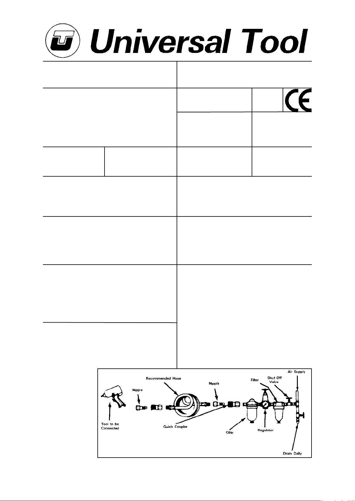
recommended that the tool is connected to the air supply as shown in
figure 1. Do not connect the tool to the air line system without
incorporating an easy to reach and operate air shut off valve. The air
supply should be lubricated. It is strongly recommended that an air filter,
regulator, lubricator (FRL) is used as shown in Figure 1 as this will supply
clean, lubricated air at the correct pressure to the tool. Details of such
equipment can be obtained from your supplier. If such equipment is not
used then the tool should be lubricated by shutting off the air supply to
the tool, depressurising the line by pressing the trigger on the tool.
Disconnect the air line and pour into the intake bushing a teaspoonful
Hose Length
Page No 1
Page 2

(5ml) of a suitable pneumatic motor lubricating oil preferably
incorporating a rust inhibitor. Reconnect tool to air supply and run tool
slowly for a few seconds to allow air to circulate the oil. If tool is used
frequently lubricate on daily basis and if tool starts to slow or lose power.
It is recommended that the air pressure at the tool whilst the tool is
running is 90 p.s.i./6.3 bar. The tool can run at lower and higher
pressures with the maximum permitted working air pressure of 100
p.s.i./7.0 bar.
parts with a molybdenum or lithium based general purpose grease.
Before reassembling the motor, make sure that the faces of end plate
(16) & (21) that abut cylinder (17) are flat and free from burs. If
necessary lap on a flat fine grade of abrasive paper. Reassemble in the
reverse order.
When refitting the complete motor assembly to the pistol housing (1)
first make sure that the motor assembly is clamped tightly together and
that the rotor spins freely. Reassemble in the reverse order, reset the
clutch as required and set the correct air pressure.
Operating
Select the correct screwdriver bit or fastener driver to suit the screw or
fastener to be tightened or loosened. Insert appropriate drive bit.
This model has an adjustable clutch so that the torque applied to the
fastener can be adjusted to give the required tightness within the torque
range of the tool. To set the tool to give a particular torque output, turn
the torque ring (55) to the right to increase the torque output or to the
left to decrease the torque output. This screwdriver has a push to start
system which eliminates the use of a throttle lever; the air motor will
automatically stop when the screwdriver reaches the pre-set torque
If the fastener is not sufficiently tightened or cannot be loosened then
the tool in adjustable clutch mode has insufficient capacity. Select a
more powerful tool.
The person setting up the tool must be aware of this torque reaction at
high setting levels of the clutch and that the tool will try to turn against
the hand. All that is required is a firm grip.
The only thing that will affect the output is a change in the air supply
pressure. The output can be increased up to the use of the maximum
allowed supply pressure and decreased with a reduction in supply
pressure until the tool fails to operate.
It must also be understood that even if the clutch is set to slip it may not
do so if the supply air pressure falls below the pressure at which the
clutch was set. It is therefore strongly recommended that a pressure
control valve is used. Information as to suitable equipment can be
obtained from your supplier.
When using the tool keep the screwdriver bit pressed firmly into the
screw head to avoid cam out and screw head damage.
Dismantling & Assembly Instructions
Disconnect from air supply.
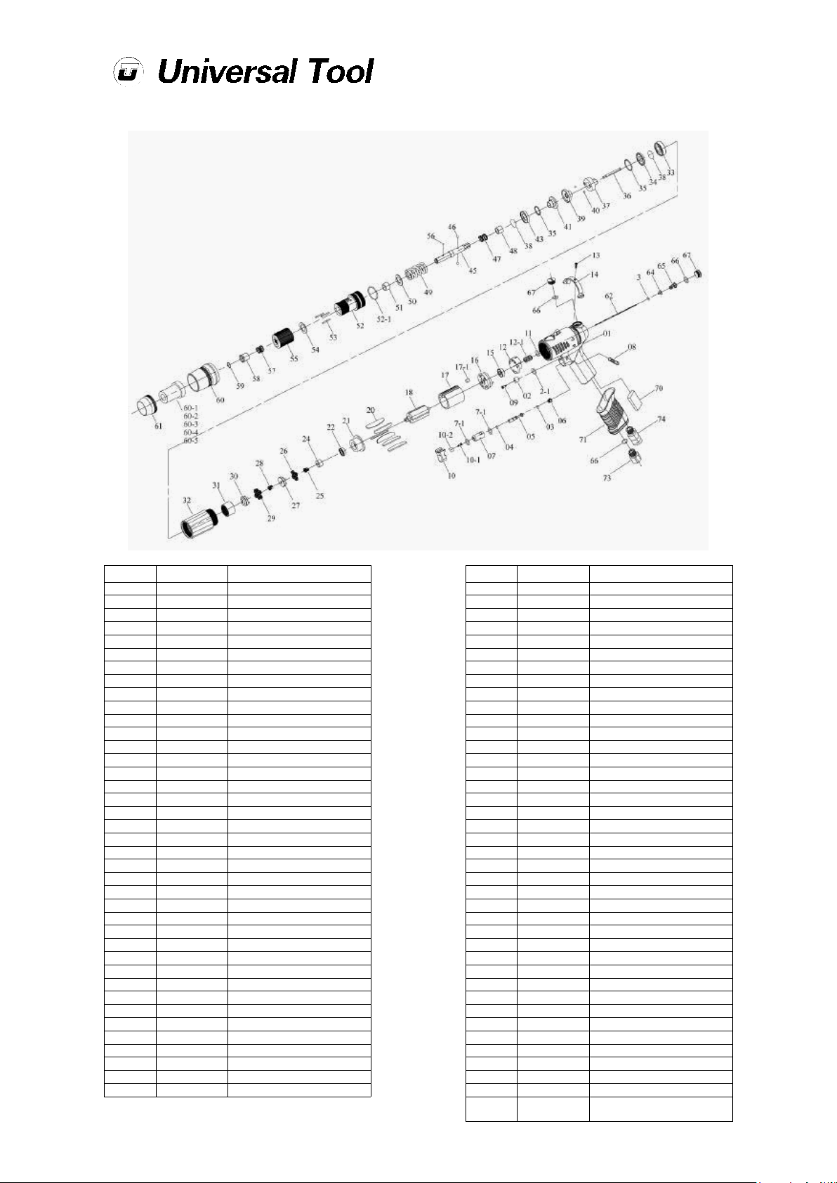
Grip the tool in a vice fitted with soft jaws. Take off rear housing (61).
Remove C ring (59) take off bit slide sleeve (58) spring (47) torque ring
(55) regulation washer (54) and needle pins (53). Unscrew clutch
housing (52) left hand thread and remove anvil bushing (51) washer
(50) torque spring (49) spring (47) and slide base (48). When removing
anvil (45) take care not to lose ball (46).
Take off C ring (38) and remove ball race (43) ball (40) end clutch (41)
centre clutch (39) ball (40) rear clutch (37) pilot pin (36) ball (35) and
retainer (34).
Take off front housing (32) then remove internal gear (31) remove
second gear cage (30) and take off second plant gear (29) and second
main gear (28) then remove first gear cage (27) and take off first plant
gear (26).
Pull out air motor from pistol housing (1) tap end of rotor and remove
front plate (21) and remove bearing (22) take off cylinder (17) and
remove rotor blades (20) then tap off end plate (16) and remove
bearing (15). Pull out valve (12) and o-ring (10).
To remove the valve assembly first take off button (10) and remove lock
pin (8) then pull out valve assembly (7-1, 7, 4, 5, 3, and 6) then unscrew
the cap screw (67) and remove (66, 65, 64, 3 and the operating rod
(62). Too remove the reverse switch take out set screw (13) and pull off
switch (14). Removing the silencers:- unscrew second silencer (74)
and pull out first silencer (70).
Reassembly
Clean all components and examine for wear and tear. Look in particular
for wear and cuts on O-rings, wear on rotor blades, gears and clutch
components.
Coat all parts with pneumatic tool lubrication oil, one preferably
containing a rust inhibitor and grease all bearings, gears and clutch
Safety Rules For A Screwdriver
1) Read all the instructions before using this tool. All operators must be
fully trained in its use and aware of these safety rules.
2) Do not exceed the maximum working air pressure.
3) Use personal safety equipment.
4) Use only compressed air at the recommended conditions.
5) If the tool appears to malfunction remove from use immediately and
arrange for service and repair.
6) If the tool is used with a balancer or other support device ensure that
it is fixed securely.
7) Always keep hands away from the working attachment fitted to the
tool.
8) The tool is not electrically insulated. Never use the tool if there is any
chance of it coming into contact with live electricity.
9) Always when using the tool adopt a firm footing and/or position and
grip the tool firmly to be able to counteract any forces or reaction forces
that may be generated whilst using the tool.
10) Use only correct spare parts. Do not improvise or make temporary
repairs.
11) Do not lock, tape, wire, etc. the on/off valve in the run position. The
trigger/lever etc. must always be free to return to the 'off' position when
it is released.
12) Always shut off the air supply to the tool, and depress the
trigger/lever etc. to exhaust air from the feed hose before fitting,
adjusting or removing the working attachment.
13) Check hose and fittings regularly for wear. Replace if necessary. Do
not carry the tool by its hose and ensure the hand is remote from the
on/off control when carrying the tool with the air supply connected.
14) Take care against entanglement of moving parts of the tool with
clothing, ties, hair, cleaning rags, etc. This will cause the body to be
drawn towards the tool and can be very dangerous.
15) It is expected that users will adopt safe working practices and
observe all relevant legal requirements when installing, using or
maintaining the tool.
16) Do not install the tool unless an easily accessible and easily operable
on/off valve is incorporated in the air supply.
17) Take care that the tool exhaust air does not cause a problem or
blows on another person.
18) Never lay a tool down unless the working attachment has stopped
moving.
19) Always ensure that the reverse button is in the selected position
before starting the tool.
20) Do not use bits or sockets with excessive wear to the input and
output drives. Make sure the bit, socket, extension is firmly fixed to the
tool.
21) When loosening fasteners first ensure that there is sufficient
clearance behind the tool to avoid hand entrapment. The tool will move
away from the threaded joint as the nut/bolt is loosened and rides up
the thread moving the tool with it.
Page No 2
Page 3
UT8959
Pistol Push Start-Auto Shut Off Screwdriver
Ref No Part No Description
1 5L2100 Pistol Housing
2 2C2003 Blank Cap
2-1 7Q2008 O-Ring
3 7Q2006 O-Ring (2)
4 7Q6112 Valve O-Ring
5 6S2023 Valve Pin
6 6N2106 Cone Spring
7 6S2024 Valve Bushing
7-1 7Q2009 O-Ring (2)
8 5L2601 Lock Pin (Black)
9 7S2106 Set Screw
10 5L2701 Button (Black)
10-1 6S2032 Lock Plate Screw
10-2 6S2025 Lock Plate
11 7Q2011 Valve O-Ring
12 6S6104 Valve
12-1 6N5006 Spring
13 7S2107 Set Screw W/Washer
14 2L6012 Switch (Black)
15 7S5001 Ball Bearing
16 1S6001-A End Plate
17 1P6005 Cylinder
17-1 2S2023 Key
18 1S6045 Rotor
20 1P6051 Blade (6)
21 1P6063 Front Plate
22 7S2002 Ball Bearing
24 1S3050 Connect
25 1P2090 First/Second Main Gear
26 1P2130 First/Second Plant Gear (4)
27 1P2290 First Gear Cage
28 1G6090 Second Main Gear
29 1P6130 Second Plant Gear (4)
30 1P6288 Second Gear Cage
31 1S2061 Internal Gear
32 5A6041 Front Housing
33 7S6003 Ball Bearing
34 2S6103 Retainer
35 7S2102 Ball (57)
Feb 2009 Ver 1.00
Page No 3
Ref No Part No Description
36 3S5001 Pilot Pin
37 3S5211 Rear Clutch
38 6N2006 C Ring (2)
39 3S5217 Center Clutch
40 7S2112 Ball (2)
41 3S5221 End Clutch
43 3S5231 Ball Race
45 3S5021 Anvil (6.35Hex)
46 7S2105 Ball (2)
47 6N5110 Spring
48 3S2227 Slide Base
49 6N5002 Torque Spring
50 2S5120 Washer
51 3S2240 Anvil Bushing
52 5A5222 Clutch Housing
52-1 2Q2003 O-Ring
53 6S2012 Needle Pin (3)
54 3S5101 Regulation Washer
55 3A6030 Torque Ring
56 7S3107 Ball
57 6N2103 Spring
58 5S2001 Bit Slide Sleeve
59 6N2001 C Ring
60 5A3212 Housing Cap
60-1 5A6501 Torque Cover (Black)
60-2 5A6502 Torque Cover (Blue)
60-3 5A6503 Torque Cover (Red)
60-4 5A6504 Torque Cover (Yellow)
60-5 5A6505 Torque Cover (Green)
61 5A6036 Rear Housing
62 6S2005 Operating Rod
64 6S2021 Valve Plate
65 6N2107 Cone Spring
66 2Q5001 O-Ring (3)
67 2S2011 Screw Cap (2)
70 2P3040 First Silencer
71 5L2201 Pistol Cover (Black)
73 2S2005 Air Inlet Bushing (Pt)
74 2P3041 Second Silencer
75 5L2011
Torque Reaction Ring (Not
Shown)
Page 4
Declaration of Conformity
Universal Air Tool Company Limited
Unit 8, Lane End Industrial Park, High Wycombe, Bucks, HP14 3BY, England
declare under our sole responsibility that the product
Model UT8959 Pistol Push Start-Auto Shut Off Screwdriver, Serial Number
to which this declaration relates is in conformity with the following standard(s) or other normative document(s)
EN792 (Draft), EN292 Parts 1 & 2, ISO 8662 Parts 1 & 7, Pneurop PN8NTC1
following the provisions of
89/392/EEC as amended by 91/368/EEC & 93/44/EEC Directives
Lane End D.H.Moppett (Man. Director)
Place and date of issue Name and signature or equivalent marking of authorised person
Accessories
Notes
Distributor
This document may not be copied wholly or in part by anyone without the consent of the Directors of Universal Air Tool Company Limited
Designed & Written in the U.K.
©Copyright of Universal Air Tool Company Limited, established in the United Kingdom, 1994
Page No 4
 Loading...