

Page 1
Operator Instructions Important
t
Includes - Foreseen Use, Work Stations, Putting Into Service,
Operating, Dismantling, Assembly and Safety Rules
Manufacturer/Supplier Product Type
Universal Air Tool Company Limited
Unit 8
Lane End Industrial Park
High Wycombe
Bucks
HP14 3BY
Tel No Fax No
(01494) 883300 (01494) 883237
Read these instructions carefully before insta lling, operating,
servicing or repairing this tool. Keep these instructions in a safe
accessible place.
Straight Reversible
Screwdriver
Model No/Nos Serial No
UT8955
RPM
1600
Cycles Per Min
Product Nett Weight Recommended Use Of
2.42
1.1
Recommended Working
Recommended Minimum
Maximum
Perso n a l Sa fe t y E q ui pm en t
Use - Safety Glasses
Use - Safety Gloves
Use - Safety Boots
Use - Breathing Masks
Use - Ear Protectors
lbs
Balancer Or Support
Kg
Air Pressure
6.3
n/a
7.0
bar
bar
bar
No
90
n/a
100
Yes
Foreseen Use
These screwdrivers are designed for the tightening and
loosening of threaded fasteners within the range as specified by
the manufacturer. They should only be used in conjunction with
1/4" male hex shank screwdriver bits and fastener drivers.
Do not use the tool for any other purpose than that specified
without consulting the manufacturer or his authorised
representative.
Work Stations
The tool should only be used as a hand held, hand operated
tool. It is always recomme nded that th e tool is used wh en
standing on a solid floor. It can be used in other positions, but
before any such use the operator must be in a secure position
having a firm grip and footing. The operator must adopt a firm
grip sufficient to resist the torque reaction of the tool, i.e. the
tool will try to turn in the hand.
The operator must also be
aware t hat when lo osening
fasten ers, the tool can move
quite quick ly aw ay from the
fastener being undone. An al-
low anc e m us t b e m ade fo r
this rearwar d mo vement t o
avoid hand entrapment. The
operator must also make al-
lowance that if the tool does
turn in the hand, the hand is
not trapped against any rigid
object.
Recommended Hose Bore
Size - Minimum
3/8 10 30 10
Ins M/M Ft M
Noise Level
Sound Pressure Level 83.0 dB(A)
PSI
Test Method
PSI
est code PN8NTC1 and ISO Standard 3744
PSI
Vibration Level
Test Method
Tested in accordance with Pneurop
11.8
Tested in accordance with ISO
standards 8662 Parts1 & 7
Putting Into Service
Air Supply
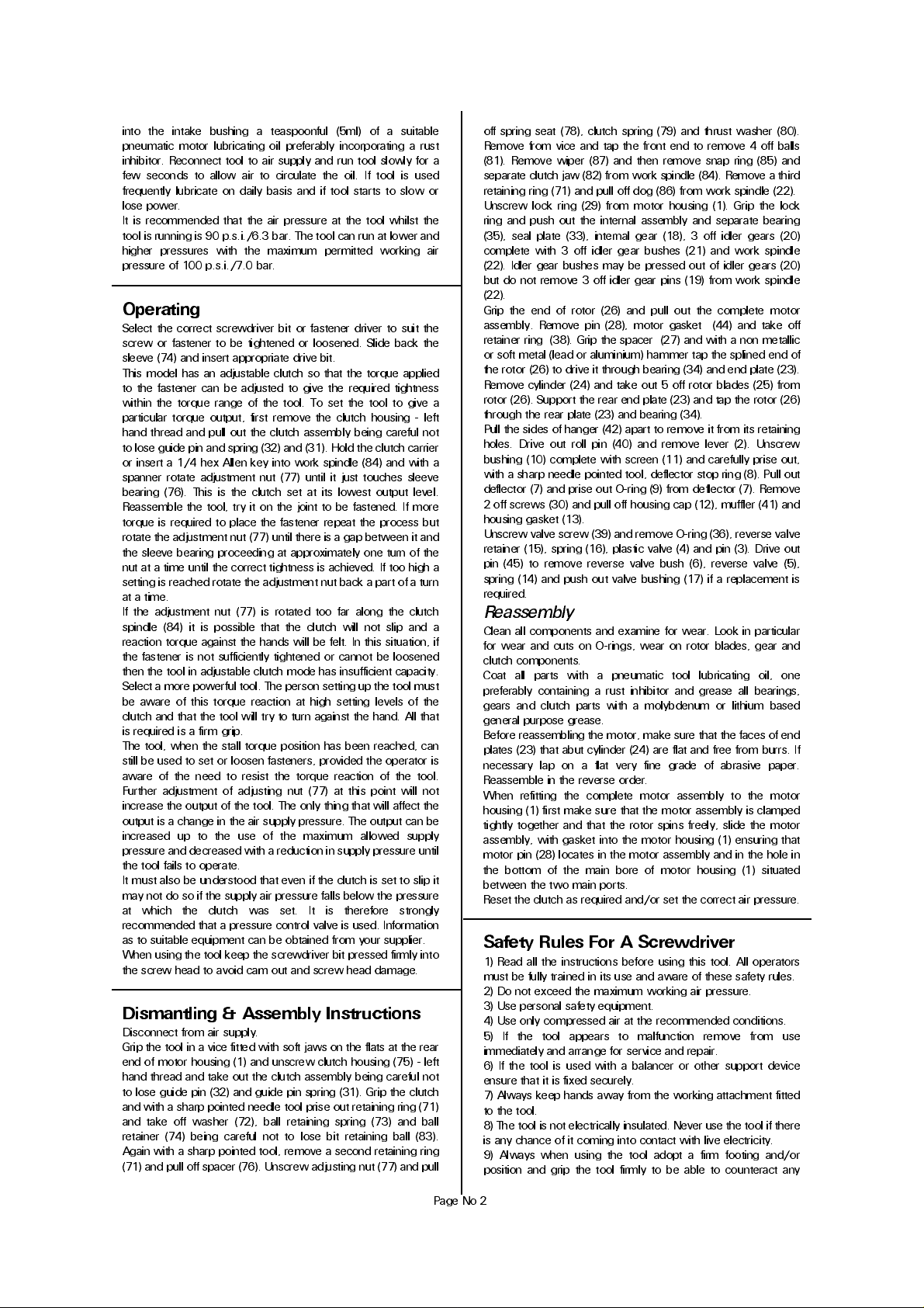
Use a clean lubricated air supply that will give a measured air
pressure at the tool of 90 p.s.i./6.3 bar when the tool is running
with the trigger fully depressed. Use recommended hose size
and length. It is recommended that the tool is connected to the
air supply as shown in figure 1. Do not connect the tool to the
air line sys tem withou t incorporating an easy to reach a nd
operate air shut off valve. The air supply should be lubricated. It
is strongly recommended that an air filter, regulator, lubricator
(FRL) is used as shown in Figure 1 as this will supply clean ,
lubricated air at the correct pressure to the tool. Details of such
equipment can be obtained from your supplier. If such
equipment is not used then the tool should be lubricated by
shutting off the air supply to the tool, depressurising the line by
pressing the trigger on the tool. Disconnect the air line and pour
Recommended Max.
Hose Length
Metres / Sec²
Page No 1
Page 2
into the intake bushing a teaspoonful (5ml) of a suitable
pneumatic motor lubricating oil preferably incorporating a rust
inhibitor. Reconnect tool to air supply and run tool slowly for a
few sec onds to allow air to circulate the oil. If tool is used
frequently lubricate on daily basis and if tool starts to slow or
lose power.
It is recommended that the air pressure at the tool whilst the
tool is running is 90 p.s.i./6.3 bar. The tool can run at lower and
higher pressures with the maximum permitted working air
pressure of 100 p.s.i./7.0 bar.
Operating
Select the correct screwdriver bit or fastener driver to suit the
screw or fastener to be tightened or loosened. Slide back the
sleeve (74) and insert appropriate drive bit.
This model has an adjustable clutch so that the torque applied
to the fastener can be adjusted to give the required tightness
within the torque range of the tool. To set the tool to give a
particular torque output, first remove the clutch housin g - left
hand thread and pull out the clutch assembly being careful not
to lose guide pin and spring (32) and (31). Hold the clutch carrier
or insert a 1/4 hex Allen key into work spindle (84) and with a
spanner rotate adjustment nut (77) until it just touches sleeve
bearing (76). T his is the clu tch set at its lowest ou tput lev el.
Reassemble the tool, try it on the joint to be fastened. If more
torque is required to place the fastener repeat the process but
rotate the adjustment nut (77) until there is a gap between it and
the sleeve bearing proceeding at approximately one turn of the
nut at a time until the correct tightness is achieved. If too high a
setting is reached rotate the adjustment nut back a part of a turn
at a time.
If the adjustm ent nut (77) is rotated too far along the clutch
spindle (84) it is possible that th e clutch will not slip and a
reaction torque against the hands will be felt. In this situation, if
the fastener is not sufficiently tightened or cannot be loosened
then the tool in adjustable clutch mode has insufficient capacity.
Select a more powerful tool. The person setting up the tool must
be aware of this torque reaction at high setting levels of the
clutch and that the tool will try to turn against the hand. All that
is required is a firm grip.
The tool, when the stall torque position has been reached, can
still be used to set or loosen fasteners, provided the operator is
aware of the need to resist the torque reaction of the tool.
Furth er adjustment of adjustin g nut (77) at th is point will not
increase the output of the tool. The only thing that will affect the
output is a change in the air supply pressure. The output can be
increased up to the use of the maximum allowed supply
pressure and decreased with a reduction in supply pressure until
the tool fails to operate.
It must also be understood that even if the clutch is set to slip it
may not do so if the supply air pressure falls below the pressure
at which the clutch was set. It is therefore strongly
recommended that a pressure control valve is used. Information
as to suitable equipment can be obtained from your supplier.
When using the tool keep the screwdriver bit pressed firmly into
the screw head to avoid cam out and screw head damage.
Dismantling & Assembly Instructions
Disconnect from air supply.
Grip the tool in a vice fitted with soft jaws on the flats at the rear
end of motor housing (1) and unscrew clutch housing (75) - left
hand thread and take out the clutch assembly being careful not
to lose guide pin (32) and guide pin spring (31). Grip the clutch
and with a sharp pointed needle tool prise out retaining ring (71)
and tak e off wash er (72), ball retain ing spring (73) and ball
retaine r (74) being careful not to lose bit retaining ball (83).
Again with a sharp pointed tool, remove a second retaining ring
(71) and pull off spacer (76). Unscrew adjusting nut (77) and pull
off spring seat (78), clutch spring (79) and thrust washer (80).
Remove from vice and tap the front end to remove 4 off balls
(81). Remove wiper (87) and then remove snap ring (85) and
separate clutch jaw (82) from work spindle (84). Remove a third
retaining ring (71) and pull off dog (86) from work spindle (22).
Unscrew lock ring (29) from motor housing (1). Grip the lock
ring and push out the internal assembly and separate bearing
(35), seal plat e (33), internal gear (18), 3 off idler gears (20)
complete with 3 off idler gear bushes (21) and work spindle
(22). Idler gear bushes may be pressed out of idler gears (20)
but do not remove 3 off idler gear pins (19) from work spindle
(22).
Grip the end of rotor (26) and pull out the complete motor
asse mbly. Remove pin (28), motor gask et (44) and take off
retainer ring (38). Grip the spacer (27) and with a non metallic
or soft metal (lead or aluminium) hammer tap the splined end of
the rotor (26) to drive it through bearing (34) and end plate (23).
Remove cylinder (24) and take out 5 off rotor blades (25) from
rotor (26). Support the rear end plate (23) and tap the rotor (26)
through the rear plate (23) and bearing (34).
Pull the sides of hanger (42) apart to remove it from its retaining
holes. Drive out roll pin (40) and remove leve r (2). Unscre w
bushing (10) complete with screen (11) and carefully prise out,
with a sharp needle pointed tool, deflector stop ring (8). Pull out
deflector (7) and prise out O-ring (9) from deflector (7). Remove
2 off screws (30) and pull off housing cap (12), muffler (41) and
housing gasket (13).
Unscrew valve screw (39) and remove O-ring (36), reverse valve
retainer (15), spring (16), plastic valve (4) and pin (3). Drive out
pin (45) to remove re verse valve bus h (6), reverse valv e (5),
spring (14) and push out valve bushing (17) if a replacement is
required.
Reassembly
Clean all components and examine for wear. Look in particular
for wear and cuts on O-rings, wear on rotor blades, gear and
clutch components.
Coat all parts with a pneumatic tool lubricating oil, one
preferably containing a ru st inhibitor and gre ase all bearin gs,
gears a nd clutch parts with a molybdenu m or lithium based
general purpose grease.
Before reassembling the motor, make sure that the faces of end
plates (23) that abut cylinder (24) are flat and free from burrs. If
necessary lap on a flat very fine grade of abrasive paper.
Reassemble in the reverse order.
When re fitting the comple te motor a sse m bly to the motor
housing (1) first make sure that the motor assembly is clamped
tightly together and that the rotor spins freely, slide the motor
assembly, with gasket into the motor housing (1) ensuring that
motor pin (28) locates in the motor assembly and in the hole in
the bottom of the main bore of motor housing (1) situated
between the two main ports.
Reset the clutch as required and/or set the correct air pressure.
Safety Rules For A Screwdriver
1) Read all the instructions before using this tool. All operators
must be fully trained in its use and aware of these safety rules.
2) Do not exceed the maximum working air pressure.
3) Use personal safety equipment.
4) Use only compressed air at the recommended conditions.
5) I f the too l appea rs to mal functio n remove f rom use
immediately and arrange for service and repair.
6) If the tool is used with a balancer or other support device
ensure that it is fixed securely.
7) Always keep hands away from the working attachment fitted
to the tool.
8) The tool is not electrically insulated. Never use the tool if there
is any chance of it coming into contact with live electricity.
9) Always when u sing the tool a dopt a firm footing and/or
position and grip the tool firmly to be able to counteract any
Page No 2
Page 3

UT8955
Straight Reversible Screwdriver
Ref No Part No Description
1 90019 1 Motor Housi ng
2 90019 2 Throttle Lev er
3 900193 Valve Pin
4 900668 Valve
5 90019 4 Rever se Val ve
6 90019 5 Rever se Val ve Bush
7 729702 Deflector
8 729703 Deflector Stop Ring
9 1012371 O-Ring
10 900196 Bushing
11 1005726 Screen
12 900197 Housing Cap
13 900198 Housing Gasket
14 900199 Reverse Spring
15 900200 Reverse Retainer
16 729063 Valve Spring
17 900201 Valve Bushing
18 732078 Internal Gear
19 900202 Idler Gear Pin (3)
20 732079 Idler Gear (3)
21 900203 Idler Gear Bush (3)
22 900204 Work Spindle
23 900102 End Plate (2)
24 900104 Liner
25 729709 Rotor Blade (5)
26 900103 Rotor
27 900101 Spacer
28 900105 Liner Pin
29 900205 Lock Ring
30 900206 Screw (2)
Nov 2004 Ver 1.2
Ref No Part No Description
31 900207 Guide Pin Spring
32 730272 Guide Pin
33 720231 Seal Plate
34 729012 Ball Bearing (2)
35 732081 Ball Bearing
36 729088 O-Ring
38 732069 Retainer Ring
39 900208 Valve Screw
40 729167 Roll Pin
41 900209 Muffler
42 900210 Hanger
44 900113 Motor Gasket
45 731930 Roll Pin
71 730257 Retainer Ring (3)
72 730258 Washer
73 730259 Ball Ret. Spring
74 730260 Ball Retainer
75 900355 Clutch Case
76 730262 Sleeve Bearing
77 730263 Adjust Nut
78 730264 Spring Seat
79 730265 Clutch Spring
80 730266 Thrust Washer
81 1005080 Steel Ball (1/4") (4)
82 730267 Clutch Jaw
83 1005164 Steel Ball (1/8")
84 730268 Work Spindle (B)
85 730269 Snap Ring
86 730270 Dog
87 730281 Wiper
Page No 3
Page 4

A
Declaration of Conformity
Universal Air Tool Company Limited
Unit 8, Lane End Industrial Park, High Wycombe, Bucks, HP14 3BY, England
declare under our sole responsibility that the product
Model UT8955, Straight Reversible Screwdriver, Serial Number
to which this declaration relates is in conformity with the following standard(s) or other normative document(s)
EN792 (Draft), EN292 Parts 1 & 2, ISO 8662 Parts 1 & 7, Pneurop PN8NTC1
following the provisions of
89/392/EEC as amended by 91/368/EEC & 93/44/EEC Directives
Lane End D.H.Moppett (Man. Director)
Place and date of issue Name and signature or equivalent marking of authorised person
forces or reaction forces that may be generated whilst using the
tool.
10) Use only correct spare parts. Do not improvise or make
temporary repairs.
11) Do not lock, tape, w ire, etc. the on/off va lve in the run
position. The trigger/lever etc. must always be free to return to
the 'off' position when it is released.
12) Always shut off the air supply to the tool, and depress the
trigger/lever etc. to exhaust air from the feed hose before fitting,
adjusting or removing the working attachment.
13) Check hose and fittings regularly for wear. Replace if
necessary. Do not carry the tool by its hose and ensure the hand
is remote from the on/off control when carrying the tool with
the air supply connected.
14) Take care against entanglement of moving parts of the tool
with clothing, ties, hair, cleaning rags, etc. This will cause the
body to be drawn towards the tool and can be very dangerous.
15) It is expected that users will adopt safe working practices
and observe all relevant legal requiremen ts whe n installing,
using or maintaining the tool.
16) Do not install the tool unless an easily accessible and easily
operable on/off valve is incorporated in the air supply.
17) Take care that the tool exhaust air does not cause a problem
or blows on another person.
18) Never lay a tool down unless the working attachment has
stopped moving.
19) Always en sure that the reverse button is in th e selected
position before starting the tool.
20) Do not use bits or sockets with excessive wear to the input
and output drives. Make sure the bit, socket, extension is firmly
fixed to the tool.
21) When loosening fasteners first ensure that there is sufficient
clearance behind the tool to avoid hand entrapment. The tool
will move a wa y from th e th rea ded join t a s the n ut/ bolt is
loosened and rides up the thread moving the tool with it.
Notes
Distributor
ccessories
This document may not be copied wholly or in part by anyone without the consent of the Directors of Universal Air Tool Company Limited
Designed & Written in the U.K.
©Copyright of Universal Air Tool Company Limited, established in the United Kingdom, 1994
Page No 4
 Loading...