

Page 1
t
T
Operator Instructions Important
Includes - Foreseen Use, Work Stations, Putting Into Service,
Operating, Dismantling, Assembly and Safety Rules
Manufacturer/Supplier Product Type
Universal Air Tool Company Limited
Unit 8
Lane End Industrial Park
High Wycombe
Bucks
HP14 3BY
Tel No Fax No
(01494) 883300 (01494) 883237
Read these instructions carefully before insta lling, operating,
servicing or repairing this tool. Keep these instructions in a safe
accessible place.
Pistol Grip Drill
Model No/Nos Serial No (if any)
UT8830 (3/8" Cap)
UT8830-1/2 (1/2" Cap)
RPM
2,200
Cycles Per Min
Product Nett Weight
2.2 (3/8) 2.53 (1/2)
1.0 (3/8) 1.15 (1/2)
lbs
Kg
Recommended Use Of
Balancer Or Support
No
Air Pressure
Recommended Working
Recommended Minimum
Maximum
6.3
n/a
7.0
bar
bar
bar
90
n/a
100
Perso n a l Sa fe t y E q ui pm en t
Use - Safety Glasses
Yes
Use - Safety Gloves
Use - Safety Boots
Use - Breathing Masks
Use - Ear Protectors
Foreseen Use Of Tool
This drill is designed for the purpose of drilling holes in all types
of materials, i.e. metals, wood, stone, plastics etc. using drilling
bits designed for this purpose. It may be used with other forms
of cutting tools, polishing devices or for sanding using coated
abrasive products. Before using any such products first check
with the manufacturer their suitability for use with this type of
drill. Do not use bonded abrasive products (i.e. grinding wheels)
or saw blades or any device which has a permitted safe working
speed less than the free speed of the drill.
Do not use this drill for any other purpose than that specified
with out co nsul ti ng th e ma nufa ctur er or th e man uf act urer 's
authorised supplier.
Work Stations
The tool should only be
used as a handheld hand
operated tool. It is always
recommended that the
tool is used when
standing on the solid
floor. It can be in other
positions but be fore an y
such use, the operator
must be in a secure
position having a firm grip
and footing and be aware
that the drill can develop
a torque reaction see
section "Operating".
Recommended Hose Bore
Size - Minimum
3/8 10 30 10
Ins M/M Ft M
Noise Level
PSI
Test Method
PSI
est code PN8NTC1 and ISO Standard 3744
PSI
Vibration Level
Test Method
Sound Pressure Level 86.7 dB(A)
Sound Power Level 93.24 dB(A)
Tested in accordance with Pneurop
Less than 2.5
ested in accordance with ISO
standard 8662/1
Putting Into Service
Air Supply
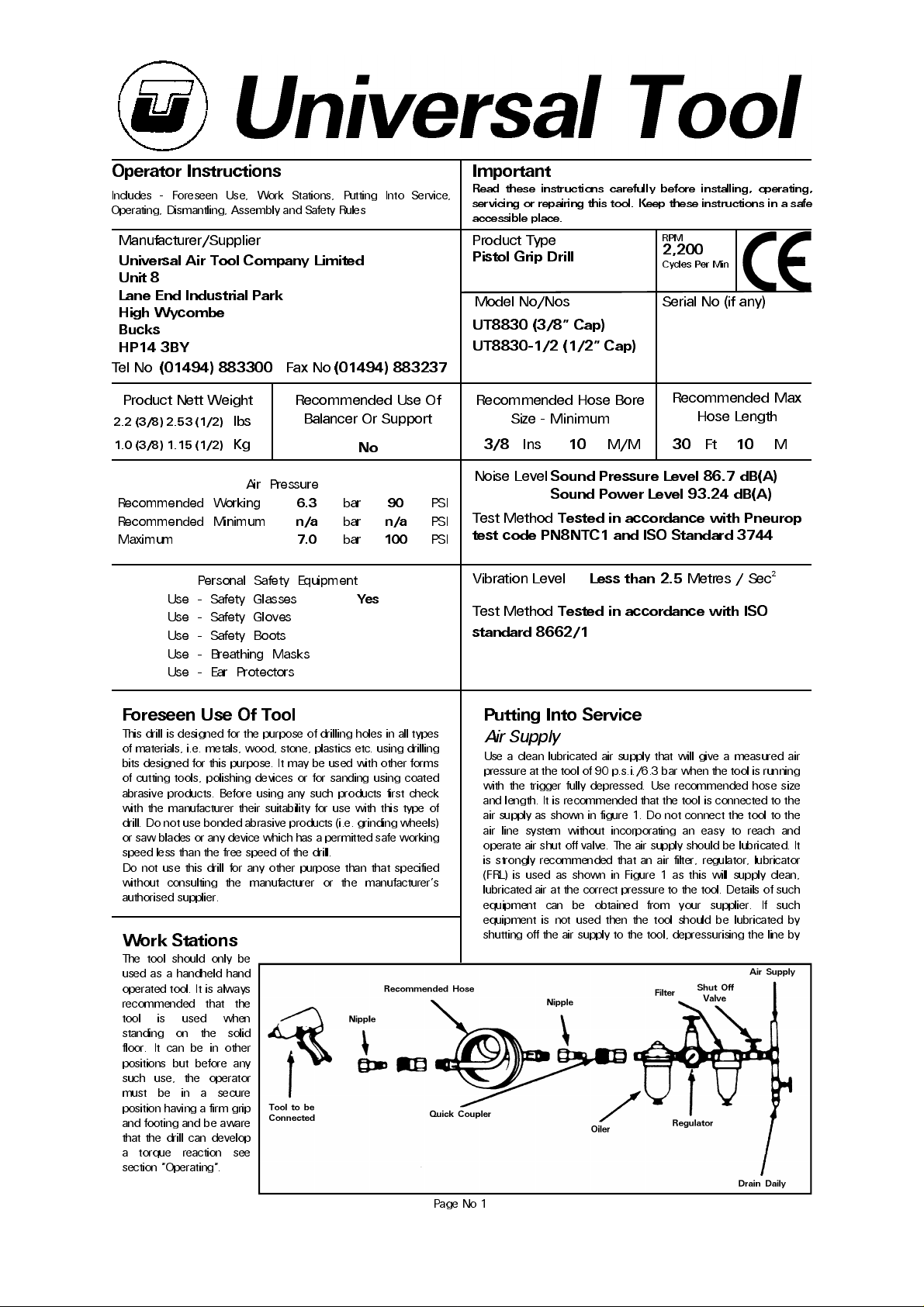
Use a clean lubricated air supply that will give a measured air
pressure at the tool of 90 p.s.i./6.3 bar when the tool is running
with the trigger fully depressed. Use recommended hose size
and length. It is recommended that the tool is connected to the
air supply as shown in figure 1. Do not connect the tool to the
air line sys tem withou t incorporating an easy to reach a nd
operate air shut off valve. The air supply should be lubricated. It
is strongly recommended that an air filter, regulator, lubricator
(FRL) is used as shown in Figure 1 as this will supply clean ,
lubricated air at the correct pressure to the tool. Details of such
equipment can be obtained from your supplier. If such
equipment is not used then the tool should be lubricated by
shutting off the air supply to the tool, depressurising the line by
Recommended Max
Hose Length
Metres / Sec²
Page No 1
Page 2
pressing the trigger on the tool. Disconnect the air line and pour
into the intake bushing a teaspoonful (5ml) of a suitable
pneumatic motor lubricating oil preferably incorporating a rust
inhibitor. Reconnect tool to air supply and run tool slowly for a
few sec onds to allow air to circulate the oil. If tool is used
frequently lubricate on daily basis and if tool starts to slow or
lose power.
It is recommended that the air pressure at the tool whilst the
tool is running is 90 p.s.i./6.3 bar. The tool can run at lower and
higher pressures with the maximum permitted working air
pressure of 150 p.s.i./10.3 bar.
Operating
Select suitable drill bit, insert the shank into the drill chuck as far
as possible and tighten chuck with key supplied making sure
that the shank of the device is securely clamped centrally
between the three chuck jaws. Remove chuck key.
When drilling holes of all sizes it is advised to use a pointed
punch to mark the centre at which the hole is to be drilled as
this will provide a starting point for the drill tip. This procedure
will prevent the drill bit from skidding, ensure that the hole is
drilled where intended and help to prevent drill breakage when
using small drills. When drilling, particularly with small diameter
drills, always try to ensure that load applied to the drill is such
that the drill bit is always at right angles to the hole being drilled.
Do not force the drill but allow it to cut.
When drilling always adopt a firm posture to be able to
counte ract an y sudden moveme nt of the drill due to torque
reaction. Such torque reaction can occur when the drill stalls
due to a too heavy load being applied or the material being too
hard or tou gh. The torque reaction c an occur w hen the drill
breaks through the material being drilled, particularly on sheet
metal . A lw ays us e eye p r ot ecti o n and hand p ro tec ti o n is
advised, particularly w hen drilling h oles in me tals whe re the
materia l being remove d from the hole is in the form of long
sharp strips. Do not tie the drill chuck key to the drill as the
attach ing device i.e. string or chain could become entangled
with the rotating chuck and bit etc.
If using a n abrasive device, drilling stone or performing a ny
operation where dust is created, it is recommended to use a
breathing mask.
Always ensure that the material to be drilled is firmly fixed to
prevent its movement.
It is also recommended that when drilling holes of large
diameter to first pre drill a hole of smaller diameter as this will
reduce effort required to drill the hole and minimise torque
reaction.
Dismantling & Assembly Instructions
Disconnect tool from air supply.
The drill chu ck (1) may be rem oved from the asse mbly by
placing the drill chuck key in the drill chuck securely and giving
the chuck key a sharp tap with a hammer in the direction to
loosen a right hand threa ded joint. If th is fails t o remove the
chuck the n r em o ve af t er t he g e ar b o x ass em bly has b een
removed from the drill assembly. (See later).
Place the motor housing (42) in a vice fitted with soft jaws with
the handle section pointing upwards, unscrew hose adaptor
(46) and remove 2 off screws (45) and take off exhaust muffler
(44). Unscrew clamp nut (2) and remove the gearbox assembly.
If the drill chuck has not successfully been removed as it is too
tightly fitted, then remove internal gear (3) and lever off bearing
(25) and grip planet cage (8) so as to be able to unscrew the drill
chuck (1). Continue to dismantle the gearbox by taking off
bearing ch uck space r (5) and bearing (4) an d fibre wash er
(6)from planet cage (8). Remove retaining ring (7). Push out 2 off
planet pins (9) and slide out 2 off planet gears (10) with 22 off
needle rollers (11). Pull out the motor a ssembly from motor
housing (42).
To dismantle the motor assembly grip the front end plate (27)
by hand and tap the splined end of rotor (28) with a non metallic
or soft metal (le ad or aluminium) ha mmer to drive the rotor
through th e front end plate (27) and bea ring (26) assembly.
Remove cylinder (30) and 4 off rotor blades (29) from rotor (28).
Do not remove 2 off pins (47) from front end plate (27) and rear
end plate (48) unless replacements are required. Prise out rear
bearing cap (12) and remove retaining ring (33). Support the
rear end plate (48) in a piece of tube with a bore diameter as
close as possible to the maximum diameter of the rotor and tap
the non splined end of the rotor to drive it through the rear end
plate (48) and bearing (49) assem bly. With a suitable pun ch
drive out bearing (26) from front end plate (27) and rear bearing
(49) from rear end plate (48).
Drive out pin (41) and slowly and carefully so as not to damage
the seal s, gr ip the tri gg er and pul l o ut the co nt ro l va l ve
assembly. Unscrew set screw (34) and ta ke off trigger (35) from
valve stem (36). Remove spring (43) and slide valve stem (36)
through valve bushing (39). Remove O-ring (37) from valve stem
(36) and O-rings (38) and (40) from valve bushing (39). Take out
O- ring (38) from motor housing (42).
Reassembly
Clean all co mp onent part s and e xamin e for wear b efo re
reass em bling. Use on ly m an u fac tu rer or distributor su pplied
spare parts. Check in particular for wear and cuts on O-rings and
wear on rotor blades. Lightly coat all parts with a suitable
pneumatic tool lubricating oil preferably one incorporating a rust
inhibitor. Pack all bearings and gearbox with a lithium or
molybdenum based general purpose grease and reassemble in
the reverse order (see note below).
For the motor assembly ensure that the front and rear end plates
that abut the cylinder are clean and free from burrs and surface
marking. If necessary lap faces that abut the cylinder on a flat
fine grade of abrasive paper. Press bearings into front and rear
end plates, support the bearing in the rear end plate on its inner
ring and ta p the rotor on its splined e nd with a soft meta llic
hammer into the bearing until the rotor locates against the rear
end plate. Support the inner face of the end plate as close as
possible to the largest diameter of the rotor and tap the non
splined end of the rotor until a clearance of 0.0015" (0.040mm)
0.0025" (0.065mm) is obtained between the inner face of the
rear end plate and the rotor. This clearance to be checked when
pulling the rotor awa y from the rear en d plate and bearing
assembly. Spin rotor to ensure that it will rotate freely in the rear
end plate bearing. Locate the cylinder by the locating pin to the
rear end plate checking that the ports in the end plate match
with those in the cylinder. Insert the four rotor blades into the
rotor and locate correctly the front end plate to the cylinder
using the locating pin. Ensure that the rotor will spin freely in the
assembly. This is best checked by placing the motor assembly
in a vee block and squeezing the front and rear end plates
against the cylinder. Fit retaining ring (33) and insert rear bearing
cap (12) into rear end plate (48).
Safety Rules When Using A Drill
1) Read all the instructions before using this tool. All operators
must be fully trained in its use and aware of these safety rules.
All service and repair must be carried out by trained personne l.
2) Always select a suitable cutting, abrasive device suitable for
use with this drill.
3) Always shut off the air supply to the drill and depress the
trigger to exhaust air from the feed hose before fitting, adjusting
or removing the device. Remove drill chuck.
4) Always adopt a firm footing and/or position and be aware of
torque reaction developed by the drill.
5) Use only correct spare parts.
6) Check hose and fittings regularly for wear. Do not carry the
tool by its hose and ensure that the hand is remote from the
Page No 2
Page 3
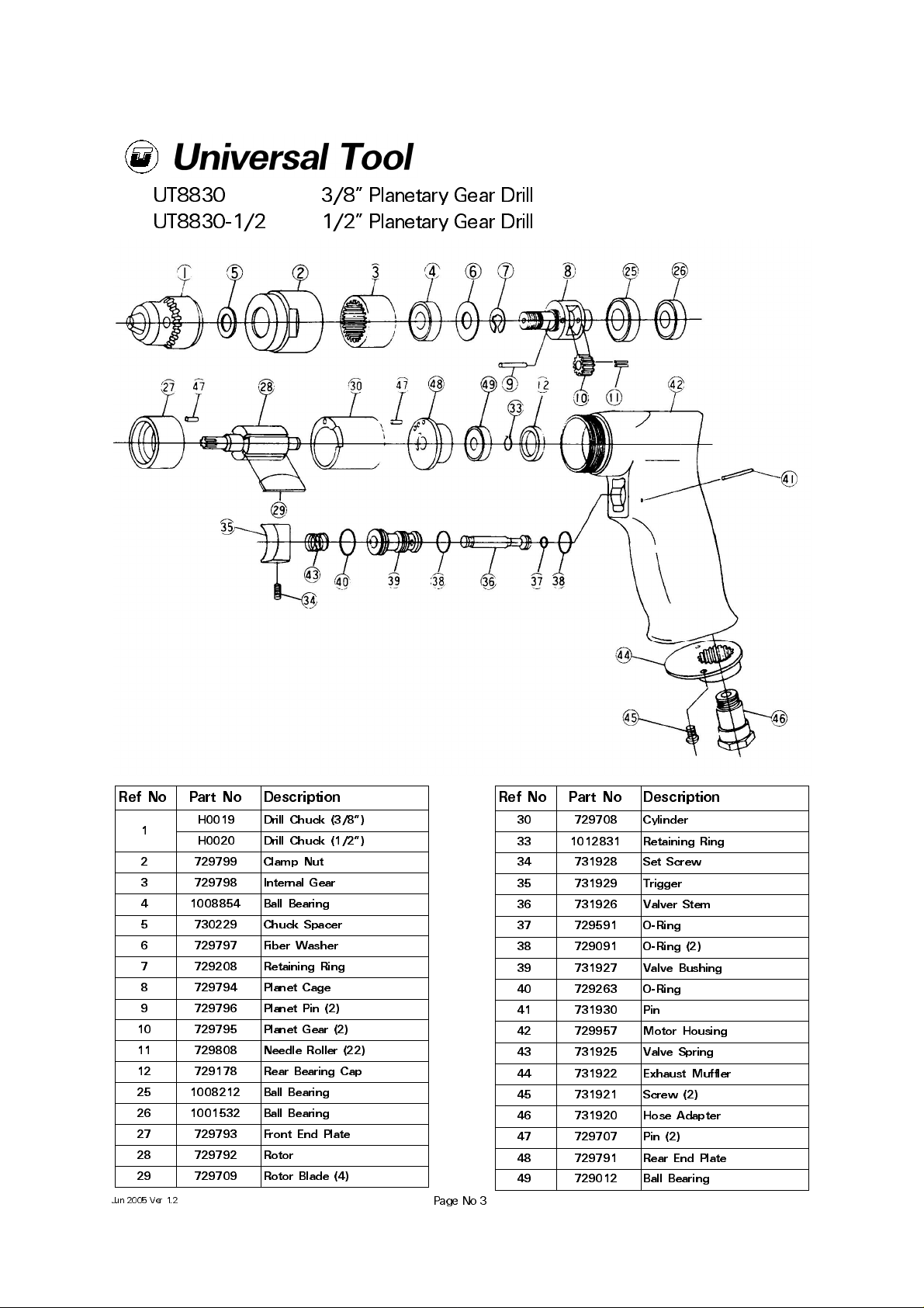
UT8830
UT8830-1/2
3/8" Planetary Gear Drill
1/2" Planetary Gear Drill
Ref No Part No Description
1
2 729799 Clamp Nut
3 729798 Internal Gear
4 1008854 Ball Bearing
5 730229 Chuck Spacer
6 729797 Fiber Washer
7 729208 Retaining Ring
8 729794 Planet Cage
9 729796 Planet Pin (2)
10 729795 Planet Gear (2)
11 729808 Needle Roller (22)
12 729178 Rear Bearing Cap
25 1008212 Ball Bearing
26 1001532 Ball Bearing
27 729793 Front End Plate
28 729792 Rotor
29 729709 Rotor Blade (4)
Jun 2005 Ver 1.2
H0019 Drill Chuck (3/8")
H0020 Drill Chuck (1/2")
Ref No Part No Description
30 729708 Cylinder
33 1012831 Retaining Ring
34 731928 Set Screw
35 731929 Trigger
36 731926 Valver Stem
37 729591 O-Ring
38 729091 O-Ring (2)
39 731927 Valve Bushing
40 729263 O-Ring
41 731930 Pin
42 729957 Motor Housing
43 731925 Valve Spring
44 731922 Exhaust Muffler
45 731921 Screw (2)
46 731920 Hose Adapter
47 729707 Pin (2)
48 729791 Rear End Plate
49 729012 Ball Bearing
Page No 3
Page 4
Declaration of Conformity
Universal Air Tool Company Limited
Unit 8, Lane End Industrial Park, High Wycombe, Bucks, HP14 3BY, England
declare under our sole responsibility that the product
Model UT8830 Pistol Grip Drill, Serial Number
to which this declaration relates is in conformity with the following standard(s) or other normative document(s)
EN792 (Draft) EN292 Parts 1 & 2 ISO 8662 Part 1 Pneurop PN8NTC1
following the provisions of
89/392/EEC as amended by 91/368/EEC & 93/44/EEC
Lane End D.H.Moppett (Man Director)
Place and date of issue Name and signature or equivalent marking of authorized person
on/off valve (trigger) when ca rrying the tool with air s upply
connected.
7) Do not exceed maximum recommended air pressure. Avoid
low air pressures as this will allow the drill to stall more easily
and develop torque reaction.
8) Use safety equipment as recommended.
9) The tool is not electrically insulated. Do not use where there
is a possibility of coming into contact with live electricity, gas
pipes, water pipes, etc. Check the area of operation before
performing the operation.
10) Take care against entanglement of moving parts of the tool
with clothing, ties, hair, cleaning rags, etc. This will cause the
body to be moved towards the work process and can be very
dangerous.
11) Do not attempt to hold or guide the drill chuck when the tool
is running. Keep hands clear of the drilling process.
12) Use only compressed air at recommended conditions.
13) Do not attempt to fit attachments, i.e. for sawing, hedge
cutting, grinding, chain sawing, etc.
14) If the tool appears to malfunction remove from use
immediately and arrange for service and repair.
15) If an additional side handle is fitted to the tool ensure that it
is correctly positioned and fixed securely.
16) If the drill is used with a balancer or other suspension device
ensure that it is fixed securely.
Accessories
Notes
Distributor
This document may not be copied wholly or in part by anyone without the consent of the Directors of Univer sal Air Tool Company Limited
Designed & Written in the U.K.
©Copyright of Universal Air Tool Company Limited, established in the United Kingdom, 1994
Page No 4
 Loading...