

Page 1
Operator Instructions Important
Includes - Foreseen Use, Work Stations, Putting Into Service, Operating,
Dismantling, Assembly and Safety Rules
Manufacturer/Supplier Product Type
Universal Air Tool Company Limited
Unit 8
Lane End Industrial Park
High Wycombe
Bucks
HP14 3BY
Tel No Fax No
(01494) 883300 (01494) 883237
Read these instructions carefully before installing, operating,
servicing or repairing this tool. Keep these instructions in a safe
accessible place.
Right Angle Paint
Surfacing Tool
Model No/Nos Serial No
UT8777
RPM
25,000
Cycles Per Min
Product Nett Weight
1.32
0.60 3/8 10 30 10
lbs
Kg
Air Pressure
Recommended Working 6.3 bar 90 PSI
Recommended Minimum n/a bar n/a PSI
Maximum 7 bar 100 PSI
Personal Safety Equipment
Use - Safety Glasses Yes
Use - Safety Gloves Yes
Use - Safety Boots
Recommended Use Of
Balancer Or Support
No
Recommended Hose Bore
Size - Minimum
Ins M/M Ft M
Noise Level Sound Pressure Level 84.7 dB(A)
Sound Power Level 95.6 dB(A)
Test Method Tested in accordance with Pneurop
test code PN8NTC1 and ISO Standard 3744
Vibration Level
Less than 2.5
Test Method Tested in accordance with ISO
standard 8662 Parts 1 & 8
Recommended Max.
Metres / Sec²
Use - Breathing Masks Yes
Use - Ear Protectors Yes
Foreseen Use of Tool
This tool is designed for the purpose of light surface
finishing/preparation. It is particularly useful for the preparation of
painted surfaces. It can be used with bristle discs or with coated
abrasive disc pads.
Do not use the tool for any other purpose than that for which it has
been designed before first seeking advice from the manufacturer or
an authorised representative.
Do not modify the tool for any other or its use as a paint surfacing tool
unless first discussing and having approval for any modification from
the manufacturer or an authorised distributor.
Work Stations
The tool should only be used as a handheld hand operated tool. It is
always recommended that the tool is used when standing on the solid
floor. It can be
used in other positions but before
any such use, the
operator must be
in a secure position having a firm
grip and footing
and be aware of
the extra safety
precautions that
must be observed
when using Grinding Machines.
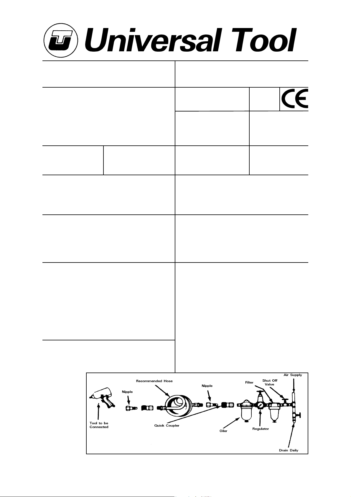
Putting Into Service
Air Supply
Use a clean lubricated air supply that will give a measured air pressure
at the tool of 90 p.s.i./6.3 bar when the tool is running with the
lever/trigger fully depressed. Use recommended hose size and
length. It is recommended that the tool is connected to the air supply
as shown in figure 1. Do not connect the tool to the air line system
without incorporating an easy to reach and operate air shut off valve.
The air supply should be lubricated. It is strongly recommended that
an air filter, regulator, lubricator (FRL) is used as shown in Figure 1 as
this will supply clean, lubricated air at the correct pressure to the tool.
Details of such equipment can be obtained from your supplier. If such
equipment is not used then the tool should be lubricated by shutting
off the air supply to the tool, depressurising the line by pressing the
lever/trigger on the tool. Disconnect the air line and pour into the
intake bushing a teaspoonful (5ml) of a suitable pneumatic motor
Hose Length
Page No 1
Page 2

lubricating oil preferably incorporating a rust inhibitor. Reconnect tool
to air supply and run tool slowly for a few seconds to allow air to
circulate the oil. If tool is used frequently lubricate on daily basis and if
tool starts to slow or lose power.
It is recommended that the air pressure at the tool whilst the tool is
running is 90 p.s.i./6.3 bar. The tool can run at lower and higher
pressures with the maximum permitted working air pressure of 100
p.s.i./7.0 bar.
If tool is used daily then every other day grease gears (27) & (32) via
grease plug (40).
Operating
The tool can be fitted with conventional coated abrasive discs or
abrasive discs that are suitable for surface preparation, particularly
paint surfaces, where paint surfaces may be cleaned, surfaced or
paint runs or uneven patches removed or smoothed.
Three types of abrasive discs are available for the tool. The disc
coloured green is grade 50, yellow is grade 80 and white is grade
120 where the lower number grade, i.e. 50 is for fast material
removal and 120 is for smoother, finer finish. Select disc as required
and grip disc holder (25) and screw on disc (26) tightly by hand. Do
not overload the tool and let the abrasive work. If required the speed
and power of the tool may be reduced by turning air controller (9)
with a screwdriver.
As it is possible that during use small pieces of the disc may break off
and dust may be created, it is important to wear personal protection.
Always use protective glasses and or face shields. Use also protective
aprons, gloves and dust extraction systems as appropriate.
5) Use only correct spare parts.
6) Check hose and fittings regularly for wear. Do not carry the tool by
its hose.
7) Do not remove and never tie down the safety lever.
8) Never exceed the maximum air pressure and check the free
running speed frequently. Have air regulator fully open.
9) Use safety equipment as recommended.
10) Take care against entanglement of moving parts of the tool with
clothing, ties, hair, cleaning rags, etc.
11) Use only compressed air at the recommended pressure.
12) Do not attempt to fit any other attachment than those
recommended - see “Foreseen Use of Tool”
13) If the tool appears to malfunction remove from use immediately
and arrange for service and repair.
Dismantling & Assembly Instructions
Disconnect the tool from the air supply.
If fitted first remove exhaust and inlet hose assemblies.
Grip disc holder (25) and unscrew and remove attachment (26) as
fitted. Grip housing (3) in a vice fitted with soft jaws and unscrew air
inlet with screen (28) and pull out exhaust sleeve (27) with O-Ring
(29). Drive out spring pin (2) and take off safety lever (1). With a wide
bladed screwdriver unscrew valve screw (12) with O-ring (11) and
take out air controller(9), O-ring (10), valve spring (8), valve stem (6)
and O-rings (5) & (7). Do not press out valve bushing (4) from housing
(3) unless a replacement is required. Unscrew lock ring (24) from
housing (3) and pull out disc holder (25) with the complete motor
assembly from housing (3). Grip rear end plate (14) and tap the non
threaded end of rotor (17) to drive rotor (17) through rear end plate
(14) assembly. Take off cylinder (16) noting how pins (15) located in
rear end plate (14) and front end plate (21) locate the cylinder to the
end plates via the narrow length wise slot in cylinder (16). Take out 4
off rotor blades (18) from rotor (17). Carefully grip rotor (17) and
unscrew disc holder (25). Pull off front end plate(21) assembly with
collar (19) and steel plate (20) from rotor (17). Tap out bearing (22)
from front end plate (21).
Reassembly
Clean all parts and examine for damage and wear. Replace any parts
with parts obtained from the manufacturer or an authorised
distributor. Assemble in the reverse order.
Safety Rules When Using A Paint
Surfacing Tool
1) Read all the instructions before using this tool. All operators must be
fully trained in its use and aware of these safety rules.
2) Always select suitable abrasive to use with this tool - see Operating
Instructions.
3) Always shut off the air supply to the tool and depress the lever to
exhaust air from the feed hose before fitting, adjusting or removing the
mounted point.
4) Always adopt a firm footing and/or position before using the tool.
Page No 2
Page 3

UT8777 Right Angle Paint Surfacing Tool
Ref No Part No Description
1 0308C001 Throttle Lever
2 0308C002 Spring Pin
3 0308C003 Housing
4 0308C004 Valve Bushing
5 0308C005 O-Ring
6 0308C006 Valve Stem
7 0308C007 O-Ring
8 0308C008 Valve Spring
9 0308C009 Air Controller
10 0308C010 O-Ring
11 0308C011 O-Ring
12 0308C012 Valve Screw
13 0308C013 Bearing
14 0308C014 End Plate
15 0308C015 Pin (2)
16 0308C016 Cylinder
17 0308C017 Rotor
18 0308C018 Blade (4)
May 98 Ver 1.0
Page No 3
Ref No Part No Description
19 0308C019 Collar
20 0308C020 Steel Plate
21 0308C021 Front Plate
22 0308C022 Bearing
24 0308C024 Lock Ring
25 0308C025 Disc Holder
26
27 0308C027 Exhaust Sleeve
28 0308C028 O-Ring
29 0308C029 Air Inlet
30 0308C030 Wrench (11 mm)
For details of suitable discs consult
supplier
Page 4

Declaration of Conformity
Universal Air Tool Company Limited
Unit 8, Lane End Industrial Park, High Wycombe, Bucks, HP14 3BY, England
declare under our sole responsibility that the product
Model UT8777 Right Angle Paint Surfacing Tool, Serial Number
to which this declaration relates is in conformity with the following standard(s) or other normative document(s)
EN792 (Draft), EN292 Parts 1 & 2, ISO 8662 Parts 1 & 8, Pneurop PN8NTC1
following the provisions of
89/392/EEC as amended by 91/368/EEC & 93/44/EEC Directives
Lane End D.H.Moppett (Man. Director)
Place and date of issue Name and signature or equivalent marking of authorised person
Technical Specification
Power 0.3 HP (224 W)
Spindle Thread Size 1/4-20 UNF
Average Air
Consumption
Overall Dimensions less
Attachments
Air Inlet 1/4 NPT
10 SCFM
155 x 80 mm
Accessories
Notes
Distributor
This document may not be copied wholly or in part by anyone without the consent of the Directors of Universal Air Tool Company Limited
Designed & Written in the U.K.
© Copyright of Universal Air Tool Company Limited, established in the United Kingdom, 1994
Page No 4
 Loading...