

Page 1

Operator Instructions
Includes - Foreseen Use, Work Stations, Putting Into Service, Operating,
Dismantling, Assembly and Safety Rules
Important
Read these instructions carefully before installing, operating,
servicing or repairing this tool. Keep these instructions in a safe
accessible place.
Manufacturer/Supplier Product Type
Universal Air Tool Company Limited
7" Dia Disc Angle Grinder
Unit 8
Lane End Industrial Park
High Wycombe
Bucks
HP14 3BY
Tel No Fax No(01494) 883300 (01494) 883237
Model No/Nos Serial No
UT8754 - with splined
output shaft
UT8754F - with 5/8”
UNC threaded shaft
RPM
7,000
Cycles Per Min
Product Nett Weight
6.38
2.9 3/8 10 30 10
lbs
Kg
Air Pressure
Recommended Working 6.3 bar 90 PSI
Recommended Minimum n/a bar n/a PSI
Recommended Use Of
Balancer Or Support
No
Recommended Hose Bore
Size - Minimum
Ins M/M Ft M
Noise Level Sound Pressure Level 90.0 dB(A)
Sound Power Level 102.0 dB(A)
Test Method Tested in accordance with Pneurop
test code PN8NTC1 and ISO Standard 3744
Maximum 7.0 bar 100 PSI
Personal Safety Equipment
Use - Safety Glasses
Use - Safety Gloves
Use - Safety Boots
Use - Breathing Masks
Use - Ear Protectors
Foreseen Use of Tool
This right angle grinder is designed to be used with reinforced resin
bonded depressed centre grinding wheels that have a permitted
rotational speed in excess of 7,000 RPM.
The tool is designed to be used for grinding and dressing of welds,
etc. but not for cutting off. The grinder must never be used if a wheel
guard (disc cover) item (3) is not fitted.
Work Stations
The tool should only be used as a hand held hand operated tool. It is
always recommended that the tool is used when standing on a solid
floor. It can be used in other positions but before any such use the
operator must be in a secure position having a firm grip and footing
and be aware of the safety rules to be obeyed when using the sander.
Vibration Level
6.2
Test Method Tested in accordance with ISO
standards 8662/1 & 8662/4
reach and operate air shut off valve. The air supply should be
lubricated. It is strongly recommended that an air filter, regulator,
lubricator (FRL) is used as shown in Figure 1 as this will supply clean,
lubricated air at the correct pressure to the tool. Details of such
equipment can be obtained from your supplier. If such equipment is
not used then the tool should be lubricated by shutting off the air
supply to the tool, depressurising the line by pressing the trigger on
the tool. Disconnect the air line and pour into the intake bushing a
teaspoonful (5ml) of a suitable pneumatic motor lubricating oil
preferably incorporating a rust inhibitor. Reconnect tool to air supply
and run tool slowly for a few seconds to allow air to circulate the oil.
If tool is used frequently lubricate on daily basis and if tool starts to
slow or lose power.
It is recommended that the air pressure at the tool whilst the tool is
running is 90 p.s.i./6.3 bar. The tool can run at lower and higher
pressures with the maximum permitted working air pressure of 100
p.s.i./7 bar.
Recommended Max.
Hose Length
Metres / Sec²
Putting Into Service
Air Supply
Use a clean lubricated air supply
that will give a measured air pressure at the tool of 90 p.s.i./6.3 bar
when the tool is running with the
trigger/lever fully depressed. Use
recommended hose size and
length. It is recommended that the
tool is connected to the air supply
as shown in figure 1. Do not connect the tool to the air line system
without incorporating an easy to
Page No 1
Page 2

Operating
With the grinder correctly connected to the air supply, check the
speed of the grinder with an inlet pressure of 100 psi/7.0 bar
measured at the tool inlet. Check with a calibrated tachometer. Check
that the guard is in position and securely fixed. Check that the grinding
wheel is of correct dimensions, is not cracked or chipped and has a
permitted speed rating higher than the maximum permissible running
speed of the grinder which is 7,000 RPM. Check that item 5 disc
receiver is the correct type as parts list and is screwed tightly to the
shaft and locates the bore of the grinding wheel on the spigot of the
disc receiver and screw on disc nut item (4) using the spanners
provided. Note on model with splined output shaft disc receiver (5)
and disc nut (4) are retained by the disc stop screw (54). Do not over
tighten as this could crack the wheel. It should be tight enough to
prevent wheel spin off when the air supply is shut off.
When first starting the grinder with a new or changed wheel fitted, the
grinder should first be started in a protected area, i.e. such as under
a heavy bench well away from other persons and run for, say, one
minute. This will provide protection if the wheel should break because
some fault was not detected.
Always use eye protection and wear protective gloves if there are
sharp edges in the working area. The tool and the grinding process
can create a noise level such that ear protectors should be worn.
If the grinding process creates a dust then use a suitable breathing
mask.
Check that the material being worked will not cause harmful dust or
fumes. If this is so then special breathing apparatus may be required.
Seek advice before starting work.
If the grinder vibrates when first fitting the wheel or during use, remove
from service immediately and arrange for the fault to be corrected
before continuing to use.
Do not apply excessive pressure as this will reduce the cutting
efficiency. Apply light loads and allow the wheel to cut.
Handle the grinder with care. If the grinder is dropped, carefully
examine the wheel for damage and replace if necessary. Start the
machine as if for the first time of fitting a wheel, i.e. under a bench.
Make sure the object to be ground is in a firm fixed position.
Dismantling & Assembly Instructions
This tool has either an output shaft with 5/8 UNC threaded shaft or a
splined drive shaft.
Disconnect tool from air supply.
To dismantle the threaded shaft version, insert the peg spanner (70)
into disc nut (4) and with a spanner (38) on the flats of gear shaft (10)
unscrew disc nut (4), take off disc (49) and unscrew disc receiver (5).
For the splined output driver version, again grip gear shaft (10) with a
spanner (38) and insert allen key (39) into disc stop screw (54) and
remove it to release disc nut (4), disc (49) and disc receiver (5).
Remove cover screw (50) and nut (51) and take off disc cover (3).
Unscrew side handle (52).
Grip the valve body (58) in a vice fitted with soft jaws and take out
head screw (2) and screw (55) and with a suitable peg spanner
unscrew [left hand thread] bearing screw (27). Grip gear shaft (10)
and pull out the bevel gear drive assembly. Remove ring (12) and
support bearing (8), bevel gear (9), wave washer (13) and key (11).
Through the small hole in body (1A) tap out spacer (6) and bearing (7)
with a small punch. Take out capscrew (56) to remove exhaust
deflector (57). Take out 4 off screws (29) with lockwashers (30) and
take off valve body assembly and gasket (48). Pull out the motor
assembly complete with bevel drive and governor assembly from
body (1A).
To dismantle this assembly remove retaining ring (20) and pull off
bevel pinion (17) with bearing (16). Grip splined end of the rotor (24)
carefully so as not to damage the splines and unscrew [left hand
thread] the governor assembly by using a spanner on the flat sides of
governor (32). Hold front case (21) and with a non metallic or soft
metal [lead or aluminium] hammer so as not to damage the splines,
tap rotor (24) through the front case and bearing assembly. Pinion
(17) may be pressed out of bearing (16) and bearing (15) tapped out
of front case (21). Take off cylinder (22) but do not remove the 2 off
pins from cylinder (22) unless replacements are required - note
orientation of cylinder (22) to front case (21) and rear case (26) for
reassembly. Remove 4 off rotor blades (23) from rotor (24). Support
rear case (26) in a piece of tube with a bore as close as possible to
the maximum diameter of the rotor and tap the non splined end of the
rotor to drive it through the rear case and bearing assembly. Tap out
bearing (15) from rear case (26).
To dismantle the governor assembly unscrew adjust nut (18), remove
spring (35) and take out plunger (33) and adjust screw (19) assembly.
These two items (33) and (19) should not be dismantled and are only
available for spares as an assembly. Drive out 2 off spring pins (37)
and take out 6 off pendulums (31) from governor (32). When
removing the pendulums from the assembly take special note of the
orientation to ensure that they are assembled in the same way on
reassembly. This is Important.
To dismantle the valve body assembly unscrew hose adaptor (64),
drive out pin (60) to remove lever (59). Remove retaining ring (63) and
take out lock pin (62)and spring (61). Unscrew valve screw (65) and
take out O-ring (66), spring (67) valve stem (68) and O-ring (69).
Reassembly
Clean all parts and examine for wear. Use only distributor or
manufacturer supplied spare parts. Particularly examine O-rings,
bearings and gears. Coat all parts in a pneumatic tool lubricating oil,
one preferably containing a rust inhibitor. Grease bearings and gears
with a molybdenum or lithium based general purpose grease.
Reassemble in the reverse order. See Note below.
For the motor make sure that the end plates that abut the cylinder are
free from burrs and sharp edges and if necessary lap on a flat fine
grade of abrasive paper. Press bearing (15) into rear case (26) and
support the inner race of bearing (15) and press the non splined end
of rotor (24) into the assembly. Tap the rotor relative to the rear case
and bearing assembly until a clearance of approx. 0.0025”
(0.065mm) is achieved between the rotor and the rear case. Ensure
the rotor spins freely before assembling the rest of the motor assembly.
This machine has a speed controller or governor, parts (18), (35),
(19), (31), (32) (37) and (38). The correct setting of this speed
controller is critical to the safety of the tool and should only be carried
out by a trained competent person. The speed is set by assembling
the speed controller, measuring the output spindle gear shaft speed
with a calibrated tachometer. Adjustment to the spindle speed can be
made by rotating adjust nut on adjust screw (18). The speed of the
grinder running free with an air inlet pressure of 100 psi (7 bar)
measured at inlet bushing (64) must not exceed 12000 RPM.
Safety Rules For A Grinder
1) Read all the instructions before using this tool. All operators must be
fully trained in its use and aware of these safety rules.
2) Do not exceed the maximum working air pressure.
3) Use personal safety equipment.
4) Use only compressed air at the recommended conditions.
5) If the tool appears to malfunction remove from use immediately
and arrange for service and repair.
6) If the tool is used with a balancer or other support device ensure
that it is fixed securely.
7) Always keep hands away from the working attachment fitted to the
tool.
8) The tool is not electrically insulated. Never use the tool if there is any
chance of it coming into contact with live electricity.
9) Always when using the tool adopt a firm footing and/or position
and grip the tool firmly to be able to counteract any forces or reaction
forces that may be generated whilst using the tool.
10) Use only correct spare parts. Do not improvise or make
temporary repairs.
11) Do not lock, tape, wire, etc. the on/off valve in the run position.
The trigger/lever etc. must always be free to return to the ‘off’ position
when it is released.
12) Always shut off the air supply to the tool, and depress the
trigger/lever etc. to exhaust air from the feed hose before fitting,
Page No 2
Page 3
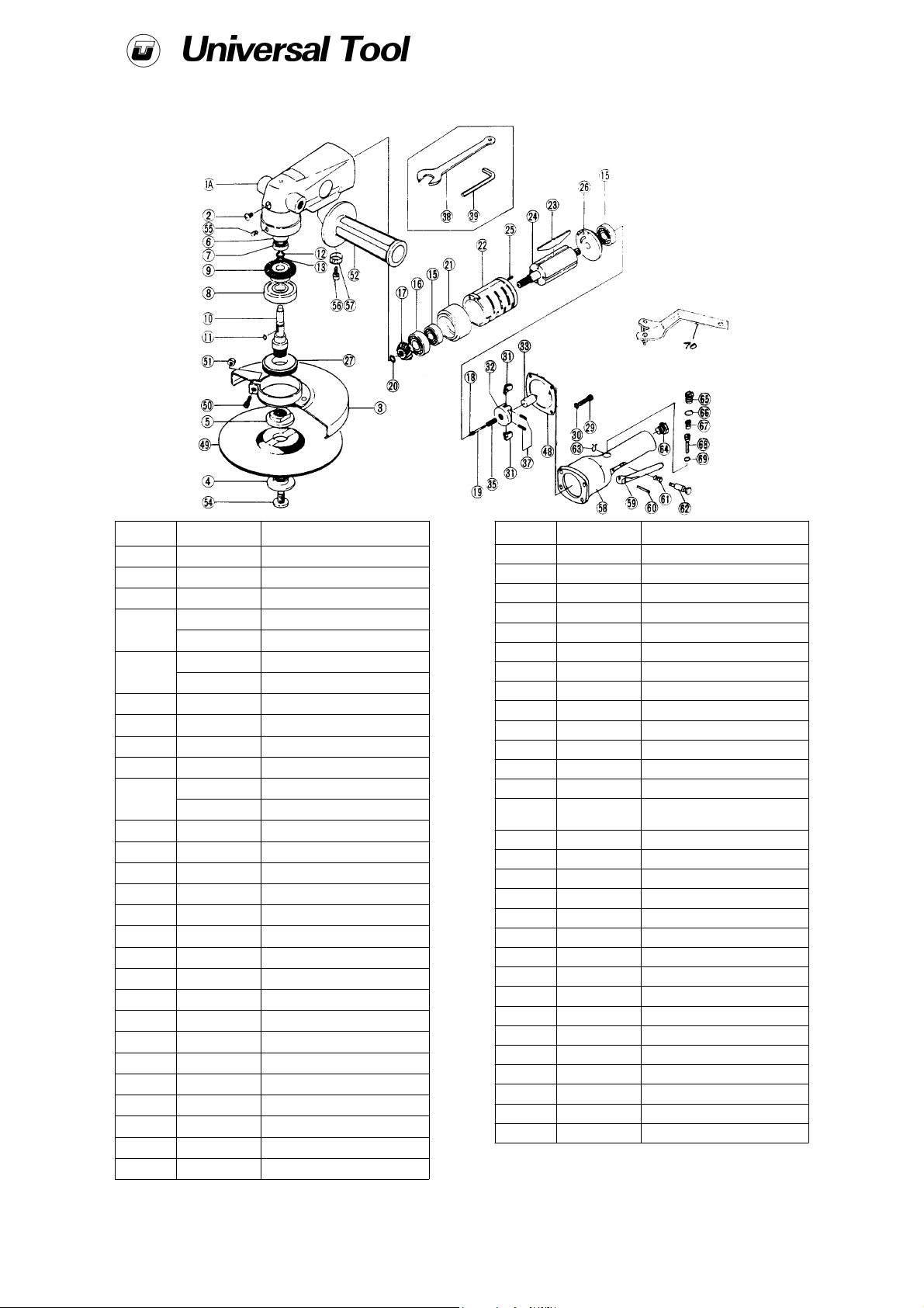
UT8754 7" Dia Disc Angle Grinder
Ref No Part No Description
1A 900304 Body
2 732344 Head Screw
3 900305 Disc Cover
4
5
6 900308 Spacer
7 900309 Ball Bearing
8 900310 Ball Bearing
9 900311 Bevel Gear
10
11 900313 Key
12 729290 Retaining Ring
13 732919 Wave Washer
15 1005478 Ball Bearing (2)
16 900314 Ball Bearing
17 900315 Bevel Pinion
18 900316 Adjust Nut
19 900317 Adjust Screw
20 900328 Retaining Ring
21 900318 Front Case
22 900319 Cylinder
23 900320 Rotor Blade (4)
24 900321 Rotor
25 900058 Cylinder Pin (2)
26 900322 Rear Case
27 900323 Bearing Screw
29 900325 Screw (4)
900306 Disc Nut (Splined)
900658 Disc Nut (Threaded)
900307 Disc Receiver (Splined)
900657 Disc Receiver (Threaded)
900312 Gear Shaft (Splined)
900656 Gear Shaft (Threaded)
Ref No Part No Description
30 729035 Washer (4)
31 900326 Pendulum (6)
32 900327 Govenor
33 900328 Plunger
35 900329 Spring
37 900330 Pin (2)
38 1010911 Spanner
39 900331 Allen Wrench
48 900337 Gasket
49 900338 Disc
50 900339 Cover Screw
51 900340 Nut
52 729284 Dead Handle
54 900341
55 900342 Screw
56 900343 Cap Screw
57 900344 Exhaust Deflector
58 900345 Valve Body
59 900346 Lever
60 900347 Pin
61 900348 Lock Spring
62 900349 Lock Pin
63 900350 Retaining Ring
64 900351 Hose Adpater
65 732152 Valve Screw
66 729263 O-Ring
67 732154 Valve Spring
68 900352 Valve Stem
69 1008127 O-Ring
70 900877 Spanner
Disc Stop Screw (Splined
Only)
Jun 98 Ver 1.1
Page No 3
Page 4
Declaration of Conformity
Universal Air Tool Company Limited
Unit 8, Lane End Industrial Park, High Wycombe, Bucks, HP14 3BY, England
declare under our sole responsibility that the product
Model UT8754 7” Dia Disc Angle Grinder, Serial Number
to which this declaration relates is in conformity with the following standard(s) or other normative document(s)
EN792 (Draft), EN292 Parts 1 & 2, ISO 8662 Parts 1 & 4, Pneurop PN8NTC1
following the provisions of
89/392/EEC as amended by 91/368/EEC & 93/44/EEC Directives
Lane End D.H.Moppett (Man Director)
Place and date of issue Name and signature or equivalent marking of authorised person
adjusting or removing the working attachment.
13) Check hose and fittings regularly for wear. Replace if necessary.
Do not carry the tool by its hose and ensure the hand is remote from
the on/off control when carrying the tool with the air supply connected.
14) Take care against entanglement of moving parts of the tool with
clothing, ties, hair, cleaning rags, etc. This will cause the body to be
drawn towards the tool and can be very dangerous.
15) It is expected that users will adopt safe working practices and
observe all relevant legal requirements when installing, using or
maintaining the tool.
16) Do not install the tool unless an easily accessible and easily
operable on/off valve is incorporated in the air supply.
17) Take care that the tool exhaust air does not cause a problem or
blows on another person.
18) Never lay a tool down unless the working attachment has
stopped moving.
19) A grinding wheel should only be fitted by a competent person
trained to do so. The wheel must be of the correct size and speed
rating.
20) Check the speed of the grinder at least once per week, if it is in
regular use, with an accurate tachometer.
21) The tool must only be used with the grinding wheels as set out in
section “Foreseen Use of the Tool” and shown on parts list. Never fit
any other device.
22) Carry out the instructions as set out in “Putting into Service”.
23) Many countries have local or national rules re the use and fitting
of grinding wheels. Make sure such rules are observed.
24) Use a barrier to prevent sparks causing a hazard to the operator,
any other person or anything within the vicinity of the sparks.
25) If a wheel guard becomes damaged or has withstood a wheel
breakage, the guard must be changed.
26) Do not use chipped or cracked grinding wheels.
27) Always wear impact resistant eye protection.
28) Use only the disc plates, Items (4) and (5) provided with the
grinder for locating and clamping the wheel. Never use substitutes.
Use the paper blotter fixed to the wheel as this ensures even tightness
when the wheel is secured.
29) Tighten the wheel plates sufficiently to prevent wheel spin off
when the grinder is turned off. Do not tighten excessively as this may
crack the wheel.
30) The noise from the tool or the process noise of the grinding
operation may be such that hearing protection should be worn.
31) Avoid inhaling dust from the grinding process. Wearing of a
breathing mask is recommended. Grinder certain materials may
mean that special breathing precautions are necessary. Seek advice
before using the tool.
32) Always ensure that the workpiece is firmly supported so that it
cannot move during the grinding process.
33) If the grinder is dropped do not use unless the wheel is first
checked for damage by a competent person.
34) When not in use the grinder should be stored in a safe place
where it will not be damaged. If a tool has not been used for a period
of time check the tool as for the first time of using.
35) Be aware that if the grinding process causes high vibration,
special precautions should be taken.
36) The operator should be aware that the grinding wheel will
continue to rotate after the power supply has been shut off. This could
cause a hazard.
37) Always store grinding wheels in accordance with the
manufacturer’s instructions.
38) Check frequently that the spindle thread has not become
damaged or worn.
39) Always ensure that the grinding wheel has a higher permissible
running speed to the speed of the grinder.
Accessories
Notes
Distributor
This document may not be copied wholly or in part by anyone without the consent of the Directors of Universal Air Tool Company Limited
Designed & Written in the U.K.
© Copyright of Universal Air Tool Company Limited, established in the United Kingdom, 1994
Page No 4
 Loading...