

Page 1
V
V
Operator Instructions Important
Includes - Foreseen Use, Work Stations, Putting Into Service,
Operating, Dismantling, Assembly and Safety Rules
Manufacturer/Supplier Product Type
Universal Air Tool Company Limited
Unit 8
Lane End Industrial Park
High Wycombe
Bucks
HP14 3BY
Tel No Fax No
(01494) 883300 (01494) 883237
Product Nett Weight
4.4
2.0 3/8 10 30 10
lbs
Kg
Recommended Use Of
Balancer Or Support
No
Read these instructions carefully before insta lling, operating,
servicing or repairing this tool. Keep these instructions in a safe
accessible place.
ertical Sander
ertical Polisher
Model No/Nos Serial No
UT8742 - 6,000 RPM
Vertical Sander
UT8744 - 3,000 RPM
Vertical Polisher
Recommended Hose Bore
Size - Minimum
Ins M/M Ft M
RPM
(See Below)
Cycles Per Min
Recommended Max.
Hose Length
Air Pressure
Recommended Working
Recommended Minimum
Maximum
6.3
n/a
7.0
bar
bar
bar
90
n/a
100
Perso n a l Sa fe t y E q ui pm en t
Use - Safety Glasses
Use - Safety Gloves
Yes
Yes
Use - Safety Boots
Use - Breathing Masks
Yes
Use - Ear Protectors
Foreseen Use of the Tool
This tool is designed for use with 7" diameter coated abrasive
discs of various grades of grit which are designed to be used at
the same or higher speed of this tool. The spindle thread is 5/8
- 11 UNC-2A and the tool can be us ed with other abra sive
devices that have the same female thread size and are designed
to run without a guard and have a rated speed equa l to or higher
than the speed of the tool. Do not attempt to use any bonded
abrasive devices, i.e. grinding wheels, as those which could be
fitted because of their size, cannot be used without a suitable
guard. A guard is not available for this tool.
Do not fit any form of saw blade.
Do not fit any other abrasive or cutting device before checking
the suitability for use with this tool with the manufacturer or the
manufacturer's authorised distributor.
Do not modify this tool for other use, or for its use as a sander/
polisher before checking the intended alternative use with the
manufacturer or his authorised distributor.
Noise Level
Sound Pressure Level 83.2 dB(A)
PSI
Test Method
PSI
test code PN8NTC1 and ISO Standard 3744
PSI
Vibration Level
Test Method
Tested in accordance with Pneurop
Less than 2.5
Tested in accordance with ISO
standards 8662/1 & 8662/4
Putting Into Service
Air Supply
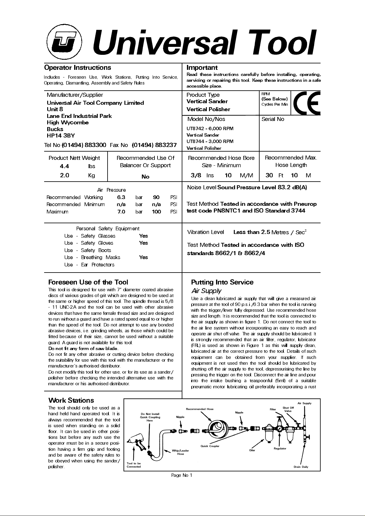
Use a clean lubricated air supply that will give a measured air
pressure at the tool of 90 p.s.i./6.3 bar when the tool is running
with the trigger/lever fully depressed. Use recommended hose
size and length. It is recommended that the tool is connected to
the air supply as shown in figure 1. Do not connect the tool to
the air line system without incorporating an easy to reach and
operate air shut off valve. The air supply should be lubricated. It
is strongly recommended that an air filter, regulator, lubricator
(FRL) is used as shown in Figure 1 as this will supply clean ,
lubricated air at the correct pressure to the tool. Details of such
equipment can be obtained from your supplier. If such
equipment is not used then the tool should be lubricated by
shutting off the air supply to the tool, depressurising the line by
pressing the trigger on the tool. Disconnect the air line and pour
into the intake bushing a teaspoonful (5ml) of a suitable
pneumatic motor lubricating oil preferably incorporating a rust
Metres / Sec²
Work Stations
The tool should only be used as a
hand held hand operate d tool. It is
always recommended that th e tool
is used when standing on a solid
floor. It can be used in other posi-
tions but before any such use the
operator must be in a secure posi-
tion hav ing a firm grip and footing
and be aware of the safety rules to
be obeyed when using the sander/
polisher.
Page No 1
Page 2
inhibitor. Reconnect tool to air supply and run tool slowly for a
few sec onds to allow air to circulate the oil. If tool is used
frequently lubricate on daily basis and if tool starts to slow or
lose power.
It is recommended that the air pressure at the tool whilst the
tool is running is 90 p.s.i./6.3 bar. The tool can run at lower and
higher pressures with the maximum permitted working air
pressure of 100 p.s.i./7 bar. The tool incorporates an air
regulator to reduce the speed of the tool if required.
Operating
Select a suitable abrasive disc (see Section "Foreseen use of the
tool") and make sure that it is fixed securely to the tool. Connect
to suitable air supply as recommended. Make sure that the side
handle is tightened securely.
Apply the sander lightly to the work and allow the abrasive disc
to cut. Take great care when sanding around sharp edges and
surfaces to avoid the disc snagging i.e. the disc may be brought
to an abrupt stop or considerably slowed that will cause the tool
to kick in the hands.
It is always recommended to use safety glasses and a breathing
mask. The sanding of certain materials may create a hazardous
dust wh ich may require s pecial brea thing equipmen t. Check
before using the tool. Even if the machine has a low noise level
the actual sanding process may cause a noise level such that
ear protectors will be required. If there are sharp areas on the
material being sanded safety gloves are recommended.
Do not continue to use abrasive discs that are worn or clogged.
This will make the sanding process inefficient and the need to
apply unnecessarily high forces to the tool.
Do not use undersized or overs ized sanding discs. T he disc
should be no more than 1/4" larger in diameter than the pad,
and not smaller than the pad.
Dismantling & Assembly Instructions.
Disconnect tool from air supply.
Grip the motor housing (1) in a vice fitted with soft jaws and
locate peg spanner provided in the two holes in nut (55) and the
open ended spanner provided on collar (33). Unscrew nut (55),
remove any abrasive disc fitted and unscrew pad (54) by ha nd.
Unscrew dead handle (3) complete with handle grip (4). Exhaust
deflector assembly may be removed from handle grip (4). Drive
out pin (6) and remove lock ing lever (7). Do not dismantle
locking lever (7). Unscrew hose adaptor (20) and it is
recommended that O-ring (37), handle (19) and handle grip (18)
are not removed unless replacements are required. Plug (2) may
be removed from housing (1).
Unscre w valve scre w (53) with O-ring (52) and take out air
regulator (50) with O-ring (51), spring (49) and valve stem (47)
with O-ring (48). O-ring (48) may be removed from valve stem
(47).
Unscrew clamp nut (34) [left hand thread] from motor housing
(1) complete with the gearbox assembly. Grip the clamp nut and
gently tap the threaded end of idler gear cage (44) [so as not to
damage the thread] and remove the assembly from the clamp
ring.
Take off collar retaining ring (32) and pull off collar (33) and
remove key (43) and pull off bearings (36) and (42), ring gear
(38) and idler gear cage washer (46) from idler gear cage (44).
Oil seal (35) may be removed from clamp ring (34).
Push out 2 off pins (39) and slide out 2 off idler gears (41)
complete with 2 off needle bearings (40) - note eleven needles
per set.
Remove retaining ring (31) from rotor (25) and take off pinion
(30). The sander is fitted with an additional collar part (61).
Grip front end plate (28) by hand and with a non m e tallic or soft
metal (lead or aluminium) hammer, tap the splined end of the
rotor (25) to drive it throu gh the front en d plate an d bearing
assembly. Take off cylinder (27) noting its orientation to the front
and re ar end plates for reassembly and take ou t 4 off rotor
blades (24) from rotor (25). Prise out bearing cap (21) and take
off retaining ring (22) from rotor (25). Support the rear end plate
(23) in a piece of tube with a bore diameter slightly larger than
the largest diameter of the rotor and tap the non splined end of
the rotor t o drive it through the re ar end plate and bea ring
assembly.
With a suitable punch tap out bearing (45) from front end plate
(28) and bearing (29) from rear end plate (23).
Reassembly
Clean all parts and examine for wear. Look in particular for wear
and cuts on O-rings. Coat all parts in a pneumatic tool lubricating
oil, preferably one including a rust inhibitor. Grease all bearings
and gears with a molybdenum or lithium based general purpose
grease and reas semble in th e reve rse order. See following
notes.
Motor Assembly
If fitting a new rotor very lightly deburr the edges of the rotor
slots. Make sure rotor blade slots are clean. Make sure that the
faces of the front and rear end plates (28) and (23) that abut
cylinder (27) are free from burrs and surface marking. If
necessary lap faces on a flat, very fine grade of abrasive paper.
Press be aring (45) into end plates (28) an d bearing (29) into
plate (23). Support bearing (29) in rear end plate on the inner
race and tap rotor on the gear end with a soft metal or non
metallic hammer until the rotor locates against the face of the
rear end plate. Support the inner face of the rear end plate in a
piece of tube with a bore diameter as close as possible to the
largest diameter of the rotor and tap the non splined end until a
clearance of .040mm (0.0015”) to .065mm (0.0025”) is
obtained between the inner face of the rear end plate and the
rotor. This clearance to be checked when pulling the rotor by
hand away from the rear end plate and bearing assembly.
Spin rotor to ensure that it will spin freely in the rear end plate
and bearing assembly. Fit rotor blades and cylinder ensuring that
the pin in one end of the rotor cylinder locates in the round hole
in the rear end plate. Push on front end plate and check that
rotor still rotates freely.
Safety Rules For A Sander/Polisher
1) Read all the instructions before using this tool. All operators
must be fully trained in its use and aware of these safety rules.
2) Do not exceed the maximu m working air pressure.
3) Use personal safety equipment.
4) Use only compressed air at the recommended conditions.
5) I f the too l appea rs to mal functio n remove f rom use
immediately and arrange for service and repair.
6) If the tool is used with a balancer or other support device
ensure that it is fixed securely.
7) Always keep hands away from the working attachment fitted
to the tool.
8) The tool is not electrically insulated. Never use the tool if there
is any chance of it coming into contact with live electricity.
9) Always when u sing the tool a dopt a firm footing and/or
position and grip the tool firmly to be able to counteract any
forces or reaction forces that may be generated whilst using the
tool.
10) Use only correct spare parts . Do not improvise or make
temporary repairs.
11) Do not lock, tape, w ire, etc. the on/off va lve in the run
position. The trigger/lever etc. must always be free to return to
the 'off' position when it is released.
12) Always shut off the air supply to the tool, and depress the
trigger/lever etc. to exhaust air from the feed hose before fitting,
adjusting or removing the working attachment.
13) Check hose and fittings regularly for wear. Replace if
necessary. Do not carry the tool by its hose and ensure the hand
is remote from the on/off control when carrying the tool with
Page No 2
Page 3
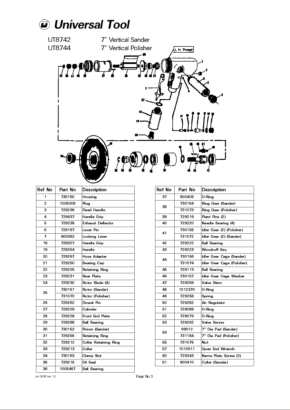
UT8742
UT8744
7" Vertical Sander
7" Vertical Polisher
Ref No Part No Description
1 730150 Housing
2 1008209 Plug
3 729236 Dead Handle
4 729437 Handle Gr ip
5 729238 Exhaust Deflector
6 729167 Lever Pin
7 900382 Locking Lever
18 729327 Handle Grip
19 729254 Handle
20 729257 Hose Adapter
21 729250 Bearing Cap
22 729225 Retaining Ring
23 729231 Rear Plate
24 729230 Rotor Blade (4)
25
26 729252 Dowel Pin
27 729229 Cylinder
28 729228 Front End Plate
29 729288 Ball Bearing
30 730152 Pinion (Sander)
31 729255 Retaining Ring
32 729212 Collar Retaining Ring
33 729213 Collar
34 730153 Clamp Nut
35 729215 Oil Seal
36 1005467 Ball Bearing
Jun 2005 Ver 1.2
730151 Rotor (Sander)
731070 Rotor (Polisher)
Page No 3
Ref No Part No Description
37 900409 O-Ring
38
39 729219 Plant Pins (2)
40 729220 Needle Bearing (4)
41
42 729222 Ball Bearing
43 729223 Woodruff Key
44
45 729113 Ball Bearing
46 730157 Idler Gear Cage Washer
47 729259 Valve Stem
48 1012370 O-Ring
49 729258 Spring
50 729282 Air Regulator
51 729088 O-Ring
52 729073 O-Ring
53 729262 Valve Screw
54
55 731075 Nut
57 1010911 Open End Wrench
60 729343 Name Plate Screw (2)
61 900410 Collar (Sander)
730154 Ring Gear (Sander)
731073 Ring Gear (Polisher)
730155 Idler Gear (2) (Polisher)
731072 Idler Gear (2) (Sander)
730156 Idler Gear Cage (Sander)
731074 Idler Gear Cage (Polisher)
99012 7" Dia Pad (Sander)
731184 7" Dia Pad (Polisher)
Page 4
Declaration of Conformity
Universal Air Tool Company Limited
Unit 8, Lane End Industrial Park, High Wycombe, Bucks, HP14 3BY, England
declare under our sole responsibility that the product
Model UT8742/4 Vertical Sander/Polisher, Serial Number
to which this declaration relates is in conformity with the following standard(s) or other normative document(s)
EN792 (Draft), EN292 Parts 1 & 2, ISO 8662 Parts 1 & 4, Pneurop PN8NTC1
following the provisions of
89/392/EEC as amended by 91/368/EEC & 93/44/EEC Directives
Lane End D.H.Moppett (Man Director)
Place and date of issue Name and signature or equivalent marking of authorised person
the air supply connected.
14) Take care against entanglement of moving parts of the tool
with clothing, ties, hair, cleaning rags, etc. This will cause the
body to be drawn towards the tool and can be very dangerous.
15) It is expected that users will adopt safe working practices
and observ e all r ele va nt lega l requ irem ents wh e n in st alling,
using or maintaining the tool.
16) Do not install the tool unless an easily accessible a nd easily
operable on/off valve is incorporated in the air supply.
17) Take care that the tool exhaust air does not cause a problem
or blows on another person.
18) Never lay a tool down unless the working attachment has
stopped moving.
19) Always check the speed of the attachment is higher than the
speed of the tool.
20) Check speed of tool at regular intervals.
21) Check always that the material to be sanded may not cause
a risk by being sanded, i.e. fire or explosion.
22) If self fixing discs are use d, i.e. self adhesiv e or Velcro,
always ensure the disc is fixed centrally to the pad.
Accessories
Notes
Distributor
This document may not be copied wholly or in part by anyone without the consent of the Directors of Univer sal Air Tool Company Limited
Designed & Written in the U.K.
©Copyright of Universal Air Tool Company Limited, established in the United Kingdom, 1994
Page No 4
 Loading...