

Page 1
Operator Instructions
Includes - Foreseen Use, Work Stations, Putting Into Service,
Operating, Dismantling, Assembly an d Safe ty Rules
Important
Read these instructions carefully before insta lling, operating,
servicing or repairing this tool. Keep these instructions in a safe
accessible place.
Manufacturer/Supplier Product Type
Universal Air Tool Company Limited
Unit 8
Lane End Industrial Park
High Wycombe
Bucks
HP14 3BY
Tel No Fax No
(01494) 883300 (01494) 883237
3/4 SD Heavy Duty Pistol
Grip Impact Wrenches
Model No/Nos Serial No
UT8355-R - Std Anvil
UT8355-RL - 6” Anvil
RPM
6,000
Cycles Per Min
Product Nett Weight
12.5
5.7
Recommended Working
Recommended Minimum
Maximum
lbs
Kg
Air Pressure
Recommended Use Of
Balancer Or Support
No
6.3
bar
90
n/a
bar
n/a
7
bar
100
Personal Safety Equipment
Use - Safety Glasses
Yes
Use - Safety Gloves
Use - Safety Boots
Use - Breathing Masks
Use - Ear Protectors
Yes
Foreseen Use Of Tool
The impact wrench is designed for the tightening and loosening
of threade d fas ten er s w ithin the ra nge as spe cifie d by the
manufacturer. It should only be used in conjunction with suitable
impact type 3/4" square female drive nut running sockets. Only
use sockets which are of the impact type.
It is allowed to use suitable extension bars, universal joints and
socket adaptors between the square output drive of the impact
wrench and the square female drive of the socket.
Do not use the tool for any other purpose than that specified
with out co nsul ti ng th e ma nufa ctur er or th e man uf act urer 's
authorised supplier. To do so may be dangerous.
Never u se an impact wre nch as a ha mmer to dislodge or
straighte n cross threaded fas teners. Never a ttempt to modify
the tool for other uses and never modify the tool for even its
recommended use as a nutrunner.
Work Stations
The tool should only be used as a handheld hand operated tool.
It is always re commended that the tool is
used when standing on the solid floor. It can
be in other positions but before any s uch
use, the operator must be in a secure
position having a firm grip and footing and be
aware that when loosening fasteners the tool
can mov e quite q uickly aw ay from t he
fasten er being undone. An allowan ce must
always be made for this rearward movement
so as to avoid the possibility of hand/arm/
body entrapment.
Recommended Hose Bore
Size - Minimum
3/8 10 30 10
Ins M/M Ft M
Noise Level
Sound Pressure Level 89.0 dB(A)
Sound Power Level 100.5 dB(A)
PSI
Test Method
PSI
test code PN8NTC1 and ISO Standard 3744
PSI
Vibration Level
Test Method
Tested in accordance with Pneurop
3.5
Tested in accordance with ISO
standards 8662 Parts 1 & 7
Putting Into Service
Air Supply
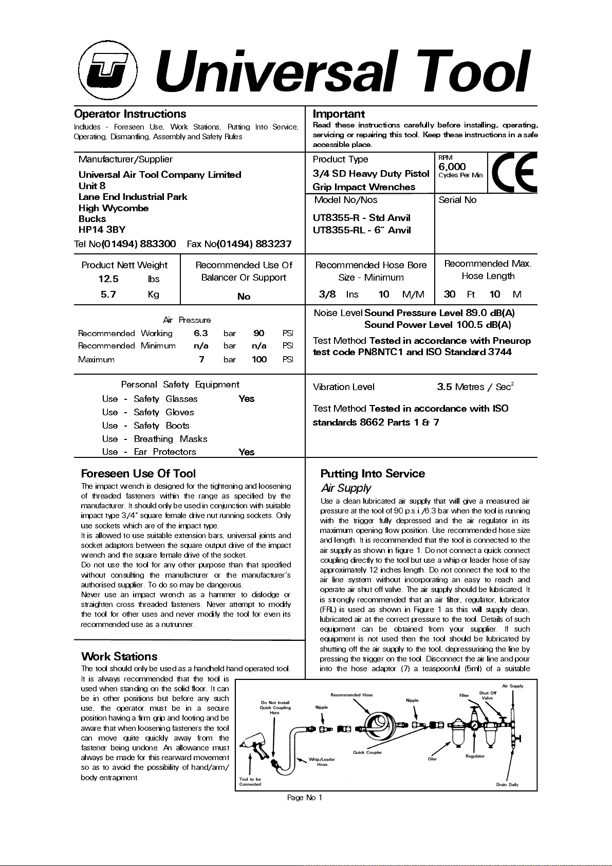
Use a clean lubricated air supply that will give a measured air
pressure at the tool of 90 p.s.i./6.3 bar when the tool is running
with the trigger fully depresse d and the air regu lator in its
maximum opening flow position. Use recommen ded hose size
and length. It is recommended that the tool is connected to the
air supply as shown in figure 1. Do not connect a quick connect
coupling directly to the tool but use a whip or leader hose of say
approximately 12 inches length. Do not connect the tool to the
air line sys tem withou t incorporating an easy to reach a nd
operate air shut off valve. The air supply should be lubricated. It
is strongly recommended that an air filter, regulator, lubricator
(FRL) is used as shown in Figure 1 as this will supply clean ,
lubricated air at the correct pressure to the tool. Details of such
equipment can be obtained from your supplier. If such
equipment is not used then the tool should be lubricated by
shutting off the air supply to the tool, depressurising the line by
pressing the trigger on the tool. Disconnect the air line and pour
into the hos e adaptor (7) a tea spoonful (5ml) of a suita ble
Recommended Max.
Hose Length
Metres / Sec²
Page No 1
Page 2
pneumatic motor lubricating oil preferably incorporating a rust
inhibitor. Reconnect tool to air supply and run tool slowly for a
few sec onds to allow air to circulate the oil. If tool is used
frequently lubricate on daily basis and if tool starts to slow or
lose power. When lubrica ting, also ensure that screen (1) is
clean.
It is recommended that the air pressure at the tool whilst the
tool is running is 90 p.s.i./6.3 bar. The tool can run at lower and
higher pressures with the maximum permitted working air
pressure of 100 p.s.i./7.0 bar. For a lower air pressure the tool
will give a lower output for a given setting of the air regulator set
for 90 p si o perat io n and an i ncrea sed o utp ut fo r hig her
pressures. Hence it is possible that changes in supply pressure
can gi ve si tuat io ns wher e the fast ener i s und er o r o ver
tightened. For changes in pressure, the regulator position and
application should be reassessed.
It is recommended that joint tightness of the threaded fastener
assembly be checked with suitable measuring equipment.
Operating
The output of the impact wrench in prime working condition is
governed by mainly three factors
a) the input air pressure
b) the time the impact wrench is operated on the joint. Normal
time for joints of average tension requirement 3 to 5 seconds
c) the setting of the air regulator for a given joint a t a given
pressure operated for a given time.
The air regulator item (24) can be used to regulate the output of
the impact wrench if no other control means is available. It is
strongly recommended that an external pressure regulator
ideally as part of a filter/regulator/lubricator (FRL) is used to
control air inlet pressure so that the pressure can be set to help
control the ten sion requ ired to be applied to the th readed
fastener joint.
There is no consistent reliable torque adjustment on an impact
wrench of this type. However, the air regulator can be used to
adjust torque to the approximate tightness of a known threaded
joint. To set the tool to the desired torque, select a nut or screw
of known tightness of the same size, thread pitch and thread
condition as those on the job. Turn air regulator to low position,
apply wrench to nut and gradually increase power (turn regulator
to admit more air) until nut moves slightly in the direction it was
originally se t. The tool is now s et to duplicate tha t tightness,
note regulator setting for future use. When tightening nuts not
requiring critical torque values, run nut up flush and then tighten
an additional one-quarter to one-half turn (slight additional
turning is necessary if gaskets are being clamped). For additional
power needed on disassembly work, turn regulator to its fully
open position. This impact wre nch is rated a 3/4" bolt size.
Rating must be down graded for spring U bolts, tie bolts, long
cap sc rews, double depth nu ts, badly rusted con ditions and
spring fasteners as they absorb much of the impact power.
When possible, clamp or wedge the bolt to prevent spring back.
Soak rusted nuts in penetrating oil and break rust seal before
removing with impact wrench. If nut does not start to move in
three to five seconds use a larger size impact wrench. Do not
use impact wrench beyond rated capacity as this will drastically
reduce tool life.
NOTE: Actual torque on a fastener is directly related to joint
hardness, tool speed, condition of socket and the time the tool
is allowed to impact.
Use the simplest possible tool-to-socket hook up. Every
connection absorbs energy and reduces power.
Dismantling & Assembly Instructions
Disconnect tool from the air supply.
Remove oil plug (3) with o-ring (2) and drain the oil contained in
the front end into a suitable container. Grip motor housing (1) in
a vice with soft jaws and remove 4 off capscrews and
Page No 2
lockwashers (31) and pull off steel housing (45). Remove o-ring
(44) and oil seal (46) and steel housing bushing (43) may be
pressed out of steel housing (45). Pull off anvil collar (42) and
anvil spacer (39) from anvil (38). Grip hammer cage (32) and pull
off the h a mme r as se mbly. Pull out a nv il (38) an d s epa rate
hammer cage (32), cam release spring (37), 2 off hammer pins
(35), hammer cam (36), ball (34) and cam ball pilot (33).
Unscrew hose adaptor with screen (7) and remove exhaust
deflector (6), throttle spring (5) and valve stem (4). Remove 2 off
screws (13) and pull out trigger assembly. Before dismantling
the trigger assembly carefully note for reassembly the
orientation of trigger (12) to the slot/groove in the end of throttle
pin (8). When reassembling, the orientation of the trigger (12) to
this groove/slot is important so that the slot/groove locates
around the end of valve stem (4). Prise off trigger (12) from
throttle pin (8) a nd separate throttle pin (8), o-ring (2), 2 off
o-rings (9), throttle bushing (10) and stop cover (11). Remove 4
off screws with lock washers (31) and pull off end cap (26)
assembly. Remove ‘C’ ring (28) from air reverse valve (24) and
remove gasket (27). Pull out air reverse valve (24) from end cap
(26) being careful not to lose stop pin (30) and stop pin spring
(29). Tap the end of rotor (20) to drive the motor assembly out
of the rea r end of motor housing (1). Pull off rear plate (22)
assembly and front plate (17) assembly from rotor (20) and
remove cylinder (18) and guide pin (21). Re move 6 off rotor
blades (19) from rotor (20). Tap out bearing (23) from rear plate
(22) and remove o-ring (16) and tap out bearing (14) and oil seal
(15) from front plate (17). Do not remove handle rubber (47)
from motor housing (1) unless a replacement is required. o-ring
(25) may be re moved from air rev erse valve (24). Remove
socket retaining ring (41) and o-ring (40) from anvil (38).
Reassembly
Clean all components and examine for wear and cracks, etc
before assembling. Look in particular for wear and cuts on o-
rings and oil seals. Check for wear and damage to rotor blades
(19) and particularly check for wear and cracks on hammer cage
(32), cam ball pilot (33), hammer pins (35), hammer cam (36)
and anvil (38) particularly in the area of the square drive. Before
reassembling the motor, first ensure that the faces of end plates
(17) and (22) that abut cylinder (18) are flat and free from
damage and burrs. If necessary lap on a flat, very find grade of
abrasive paper.
Lightly coat all parts with a pneumatic tool lubricating oil and
assemb le i n the r everse ord er. On co mpl eting assem bly ,
remove oil plug (3) with o-ring (2) and pour into the front end
one ounce (28cc) of an SAE grade 20 oil. Replace oil plug (3)
and o-ring (2). With trigger (12) depre ssed, pour into hose
adaptor (7) one teaspoonful (5ml) of a pneumatic tool lubricating
oil and release the trigger. Connect tool to a suitable air supply
and ru n tool slowly for a few s ec onds to a llow th e oil to
circulate. Reset for operation required - See Section Operating.
Safety Rules When Using an Impact
Wrench
1) Read all the instructions before using this tool. All operators
must be fully trained in its use and aware of these safety rules.
All service and repair must be carried out by trained personnel.
2) The socket used must be of the correct drive size and the
"impact" type. Never use sockets other than impact type.
3) Do not use sockets with excessive wear to the input and
output drives. Check that the square on any other type of drive
or the impact wrench is not cracked or excessively worn before
fitting or changing socket, extension, etc. Make sure that the
socket is firmly fixed to the tool.
4) Always ensure that a stable position or footing is adopted
before using the tool.
5) Ensure that the tool has been correctly set up on a test joint.
Incorrect set up could cause joint breakage with sudden and
Page 3
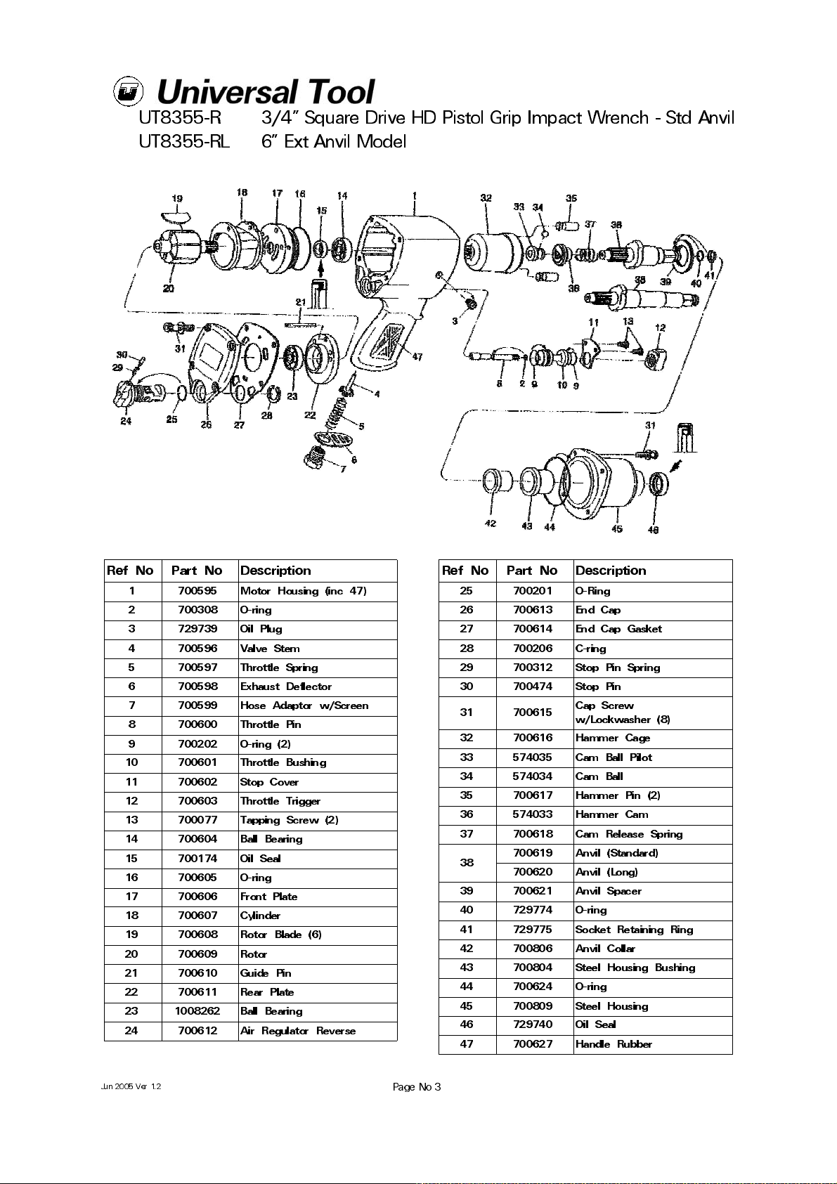
UT8355-R
UT8355-RL
3/4" Square Drive HD Pistol Grip Impact Wrench - Std Anvil
6” Ext Anvil Model
Ref No Part No Description
1 70059 5 Motor Ho usi ng (inc 47)
2 700308 O-ring
3 72973 9 Oil Pl ug
4 700596 Valve Stem
5 700597 Throttle Spring
6 70059 8 Exhaus t Def lec tor
7 70059 9 Hose Ad ap tor w /S cr een
8 700600 Throttle Pin
9 70020 2 O-ring (2)
10 700601 Throttle Bushing
11 700602 Stop Cover
12 700603 Throttle Trigger
13 700077 Tapping Screw (2)
14 700604 Ball Bearing
15 700174 Oil Seal
16 700605 O-ring
17 700606 Front Plate
18 700607 Cylinder
19 700608 Rotor Blade (6)
20 700609 Rotor
21 700610 Guide Pin
22 700611 Rear Plate
23 1008262 Ball Bearing
24 700612 Air Regulator Reverse
Ref No Part No Description
25 700201 O-Ring
26 700613 End Cap
27 700614 End Cap Gasket
28 700206 C-ring
29 700312 Stop Pin Spring
30 700474 Stop Pin
31 700615
32 700616 Hammer Cage
33 574035 Cam Ball Pilot
34 574034 Cam Ball
35 700617 Hammer Pin (2)
36 574033 Hammer Cam
37 700618 Cam Release Spring
38
39 700621 Anvil Spacer
40 729774 O-ring
41 729775 Socket Retaining Ring
42 700806 Anvil Collar
43 700804 Steel Housing Bushing
44 700624 O-ring
45 700809 Steel Housing
46 729740 Oil Seal
47 700627 Handle Rubber
700619 Anvil (Standard)
700620 Anvil (Long)
Cap Screw
w/Lo ckw a sher (8)
Jun 2005 Ver 1.2
Page No 3
Page 4
Declaration of Conformity
Universal Air Tool Company Limited
Unit 8, Lane End Industrial Park, High Wycombe, Bucks, HP14 3BY, England
declare under our sole responsibility that the product
Models UT8355-R & UT8355-RL 3/4 Impact Wrenches, Serial Number
to which this declaration relates is in conformity with the following standard(s) or other normative document(s)
EN792 (Draft), EN292 Parts 1 & 2, ISO 8662 Parts 1 & 7, Pneurop PN8NTC1
following the provisions of
89/392/EEC as amended by 91/368/EEC & 93/44/EEC Directives
Lane End D.H.Moppett (Man. Director)
Place and date of issue Name and signature or equivalent marking of authorised person
unexpected movement of the tool.
6) Use only correct spare parts for repair.
7) Always ensure that the reverse valve is in the correct position
before operating the tool. Do not run the tool unless the socket
is first located on the joint.
8) Check hose and fittings regularly for wear. Use quick connect
couplings only as recommended. See "Putting into Service". Do
not carry the tool by the hose and ensure that the hand is away
from the on/off valve when carrying.
9) Do not attempt to hold or guide the socket by hand when the
tool is running.
10) Do not exceed maximum recommended air pressure.
11) Use safety equipment as recommended.
12) The tool is not electrically insulated. Do not use where there
is a possibility of coming into contact with live electricity.
13) Preferably shut off the air supply before changing sockets or
at least ensure that the hands are well clear of the operating
trigger.
14) Take care against entanglement of moving parts of the tool
with clothing, ties, hair, cleaning rags, etc.
15) When loosening fasteners first ensure that there is sufficient
clearance behind the tool to avoid hand entrapment. The tool
will move away from the threaded joint as the nut/bolt etc. is
loosened and rides up the thread moving the tool with it.
16) Only use extensions, adaptors and universal joints suitable
for use with impact wrenches.
17) If the tool appears to malfunction remove from use
immediately and arrange for service and repair.
Notes
Distributor
Tech nica l Sp ecificat ion
Air Inlet 3/8 - 18 NPTF
Clutch Pin Type
Overall Length
(Std Anvi l)
Width 85 mm (3.1 7")
Opera tio n To rq ue
Air C ons ump tio n @ 90 PSI G
Free Ru nn ing Avg 5. 8 cf m (42 SC F M)
On Load Avg 3. 9 cf m (28 SC F M)
260 mm (9.7")
300 to 800 lbf-ft
41.5 to 110. 5 K gf - m
Accessories
This document may not be copied wholly or in part by anyone without the consent of the Directors of Universal Air Tool Company Limited
Designed & Written in the U.K.
©Copyright of Universal Air Tool Company Limited, established in the United Kingdom, 1994
Page No 4
 Loading...