

Page 1
A
Operator Instructions Important
Includes - Foreseen Use, Work Stations, Putting Into Service,
Operating, Dismantling, Assembly and Safety Rules
Manufact urer/Supplier Product Type
Universal Air Tool Company Limited
Unit 8
Lane End Industrial Park
High Wycombe
Bucks
HP14 3BY
Tel No Fax No
(01494) (01494) 883237
Read these instructions carefully before insta lling, operating,
servicing or repairing this tool. Keep these instructions in a
safe accessible place.
Pistol Rev. Screwdriver
djustable Clutch
Model No/Nos Serial No
UT5964
RPM
1,800
Cycles Per
Product Net t Weight Recommended Us e Of
2.70
1.23
Recommended Working
Recommended Minimum
Maximum
Perso n a l Sa fe t y E q ui pm en t
Use - Safety Glasses
Use - Safety Gloves
Use - Safety Boots
Use - Breathing Masks
Use - Ear Protectors
lbs
Balancer Or Su pport
Kg
Air Pressure
6.3
n/a
7.0
bar
bar
bar
No
Yes
90
n/a
100
PSI
PSI
PSI
Foreseen Use
This screwdriver is des igned for th e tightening an d loosening
of threade d fas ten er s w ithin the ra nge as spe cifie d by the
manufacturer. It should only be used in conjunction with
1/4" male hex shank screwdriver bits and fastener drivers.
Do not use the tool for any other purpose than that specified
without consulting the manufacturer or his authorised
representative.
Work Stations
The tool should only be used as a hand held, hand operated
tool. It is always recomme nded that th e tool is used wh en
standing on a s olid floor. It can be used in othe r positions,
but before any such use the operator must be in a secure
position hav ing a firm grip a nd footing. T he opera tor m ust
adopt a firm grip sufficient to resist the torque rea ction of
the tool, i.e. th e t ool will try
to turn in the hand. The
operator must also be aware
that when loosening fasteners,
the tool can move quite
quickly away from the fastener
being undone. An allowance
must be made for this rear-
ward movement to avoid hand
entrapment. The operator must
also make all owanc e that i f
the tool does turn in the hand,
the hand is not trapped
against a ny rigid object.
Recommended Hos e Bore
Size - Minimum
3/8 10 30 10
Ins M/M Ft M
Noise
Sound Pressure Level 88.0 dB(A)
Recommended Ma x.
Hose Length
Sound Power Level 100.0 dB(A)
Test Met hod
Tested in accordance with
Pneurop test code PN8NTC1 and ISO
Vibration
Test Met hod
Tested in accordance with ISO
3.7
Metres / Sec²
standards 8662 Parts 1 & 7
Putting Into Service
Air Supply
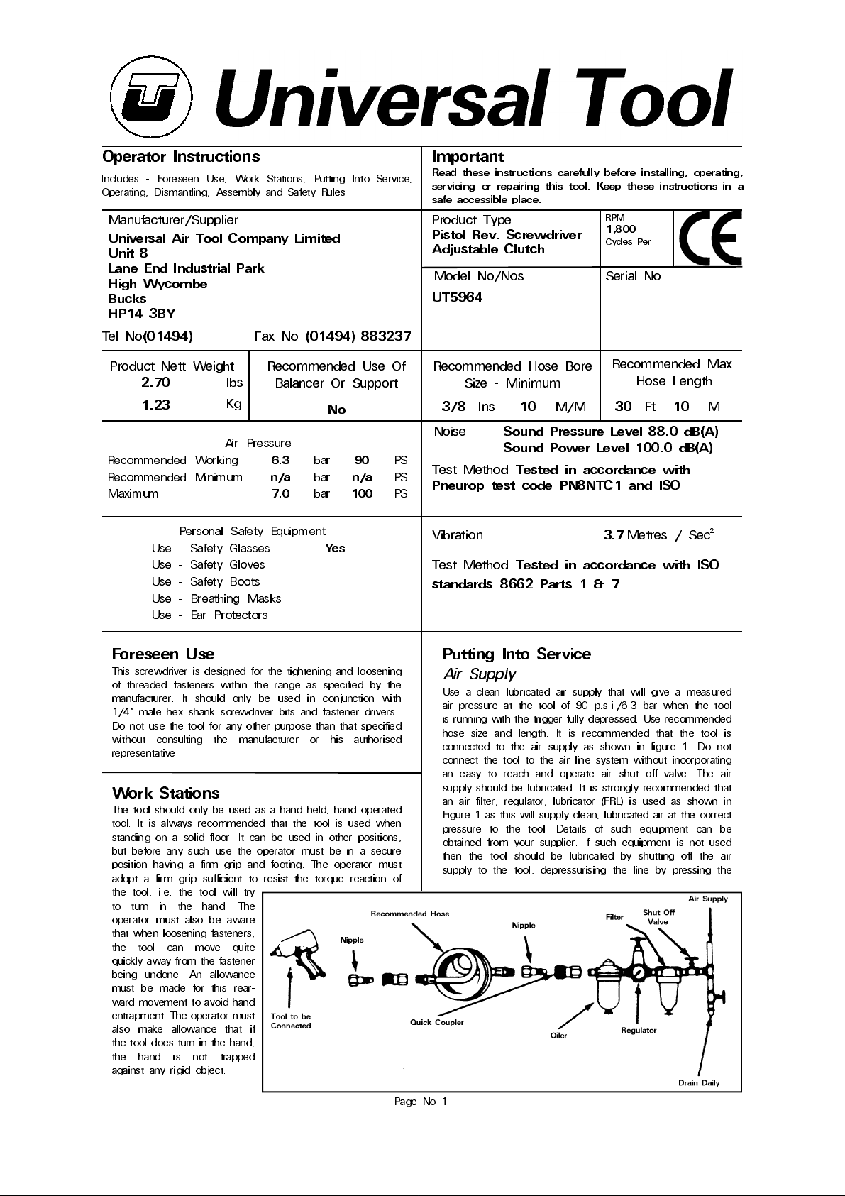
Use a c lean lubricat ed air supply that w ill give a measu red
air pressu re at the tool of 90 p.s.i./6.3 bar when the tool
is running with the trigger fully depressed. Use recommended
hose size and length. It is recommended that the tool is
conne cted to the a ir supply as s hown in figure 1. Do not
connect the tool to the air line system without incorporating
an easy to reach and operate air shut off valve. The air
supply sh ould be lubricated. It is stron gly rec ommende d that
an air filter, regulator, lubrica tor (FRL) is us ed as sh own in
Figure 1 as this will supply clean, lubricated air at the correct
pres sure t o th e too l. Deta ils of s uch eq uipm ent ca n be
obtained from your su pplier. If such equipme nt is not used
then the tool should be lubricated by shutting off the air
supply to the tool, depres su risin g the line by pre ss ing the
Page No 1
Page 2
trigger on the tool. Disconnect the air line and pour into the
intake bus h ing a tea s poonful (5ml) of a su itable pneu ma tic
motor lubricating oil preferably inc orporating a rust inhibitor.
Reconnect tool to air supply and run tool slowly for a few
second s t o al lo w ai r to ci rcul at e th e o il . I f to o l i s u sed
frequen tly lubricate on daily bas is and if tool starts to slow
or lose power.
It is recommende d that the air pressu re at the tool whilst
the tool is running is 90 p.s.i./6.3 bar. The tool can run at
lower and higher pressures with the maximum permitted
working air press ure of 100 p.s.i./7.0 bar.
Operating
Select th e corre c t sc re wdrive r bit or fa sten er drive r to s uit
the screw or fastener to be tightened or loosened. Slide
back the sleeve (4) and insert appropriate drive bit.
Model UT5964 has an adjustable clutc h so that the torque
applied to the fastener can be adjus ted to give the required
tightnes s within the torqu e range of the tool. To set the tool
to give a particular torque output, first remove the clutch
housing - left ha nd threa d and pull ou t the c lutch a ssembly
being careful not to lose guide pin and spring (23) and (24).
Hold the clutch carrier or insert a 1/4 hex Allen key in cam
spindle (14) and with a spanner rotate adjustment nut (7)
until it just touches sleeve bearing (6). This is the clutch set
at its lowest output le vel. Reassemble the tool, try it on the
joint to be fas tened. If more torque is required to place the
fastener repeat the process but rotate the adjustment nut
(7) until there is a gap betwe en it and the sleev e bearing
proceeding at a pproximately one turn of the nut a t a time
until the corre ct tightness is ac hieved. If too high a setting
is rea ched rotate th e a djustmen t nu t back a pa rt of a turn
at a time.
If the a djustm en t n ut (7) is rotate d too far a long th e c a m
spindle (14) it is possible that the clutch will not slip and a
reaction torque against the hands will be felt. In this situation,
if th e fastene r is no t suffi cient ly tig htened or canno t be
loosened then the tool in adjustable clutch mode has
insufficient capacity. Select a more powerful tool. The person
setting up th e tool must be awa re of this torque reaction at
high settin g levels of the clutc h and that the tool will try to
turn against the hand. All that is required is a firm grip.
The tool, when the stall torque position has been reached,
can still be used to set or loosen fasteners, provided the
operator is awa re of the nee d to resist the torque re action
of the tool. Further adju stm en t of adjustin g nut (7) at this
point will not increase the output of the tool. The only thing
that will affect the output is a change in the air supply
pressure. The output can be increased up to the use of the
maximum allowed supply pressure and decreased with a
reduction in supply pressure un til the tool fails to operate.
It must also be u nderstood that even if the clutch is set to
slip it may not do so if the s upply air pressu re falls below
the pr e ss ur e a t wh i ch t he cl ut c h w as set. It i s t h er ef ore
strongly re commended that a pressure control v alve is used.
Information as to suitable equipment can be obtained from
your supplier.
Dismantling & Assembly Instructions
Disconnect tool from the air supply.
Grip the tool in a vic e fitted with soft jaws on h ousing (36)
and unscrew (left hand thread) clutch housing (5) from internal
gear (22). Pull out clutch assem bly being care ful not to lose
spring guide (23) and spring (24). Grip the clutch assembly
and with a ne edle pointed tool prise out reta inin g ring (1)
and remov e washer (2) spring (3) and ball retaine r (4) being
carefu l not to los e sc rewdrive r bit reta ining ball (13). Aga in
with a ne edle pointed tool remove secon d retaining ring (1)
and pu l l off sl eev e b ea r i ng ( 6 ) . Un screw adjusting nut (7 )
and pull off was her (8), c lutch s pring (9) and wa sher (10).
Remove fr om v ice a nd ta p th e front en d to re move 4 off
balls (11). Remove retaining ring (15) and separate cam
spindle (14) from clutch carrier (12). Remove a third retaining
ring (1) and pull off drive dog (16).
Unscrew internal gear (22) from housing (36). Grip the internal
gear (22) and push out the internal gear assembly and
separate bearing (21), 3 off planet gears (26) and gear carrier
(25) with 3 off pin s. Do n ot rem ove th e 3 off pin s. Drive
out pin (37). Drive out pin and unscrew set screw to be
able to pull off trigger (47) and remove v alv e s pring (46).
Gri p thro ttle v alve (4 0) and pull out the co mpl ete valv e
asse mbly. Separate re verse va lve (43) with ball (44), O-ring
(42), reverse valve bushing (41), O-ring (39), throttle valve
(40) and O-ring (38). O-ring (39) may be taken off of throttle
valve (40). Uns cre w a ir in let (51) an d remove tw o sc rew s
(50) and take out exhaust diffuser (49). Carefully grip the
splined end of the rotor (29) and pull out the complete motor
assembly from housing (36). Remove pin (32). Remove
retainin g ring (28P) and grip bearing case (28) and with a
non met allic or soft meta l (lead or alum inium) h amme r tap
the spline d end of rotor (29) to drive it through bearing (27)
and bearing case (28). Remove cylinder (31) and 4 off rotor
blades (30) from rotor (29). Support the cylinde r side face
of end plate (33) and tap the non splined en d of the rotor
(29) to separate it from end plate (33) and bearing (34). Tap
out bearing (27) from bearing case (28).
Reassembly
Clean all components and examine for wear. Look in
particula r for cuts on O-rings and we ar on rotor blades and
clutch parts. Replace parts only with parts obtained from the
manu facturer or a n authorised dis tributor. Coat all parts w ith
a pneumatic tool lubricating oil and grease all bearings, gears
and clutch parts with a molybdenum or lithium based general
purpose greas e and reassem ble in the re verse order. Before
reassembling make sure that the faces of end plates (28)
and (33) that abut cylinder (31) are flat and free from burrs
and su r f ace m ar ki n g . I f nec es sa ry lap on a f lat very fine
grade of abrasive paper. When refitting the comple te motor
assembly in the housing (36) first make sure the assembly
is clamped tightly together and the rotor (29) spins freely.
Sli de the ass embly wi th pin ( 32) i nto the ho using ( 36)
ensuring that the motor locating pin (32) locates in the hole
in the bottom of the main bore of housing (36) situated
between the two main ports. Reassemble in the reverse
order.
Reset the clutch and/or the air pressure as required - see
Section Operating.
Safety Rules For A Screwdriver
1) Read all the instructions before using this tool. All operators
must be fully tra ined in its use and aware of these sa fety
rules.
2) Do not exceed the maximum working air pressure.
3) Use personal safety equipment.
4) Use only compressed air at the recommended conditions.
5) I f the too l appea rs to mal functio n remove f rom use
immediately and arrange for service and repair.
6) If the tool is used with a balancer or other support device
ensure that it is fixed securely.
7) Always ke ep ha nds awa y from th e work ing attac hm en t
fitted to the tool.
8) The tool is not electrically insulated. Never use the tool
if there is any chance of it coming into contact with live
electricity.
9) Always when u sing the tool a dopt a firm footing and/or
position and grip the tool firmly to be able to counteract
any force s or reaction forces th at may be genera ted whilst
Page No 2
Page 3
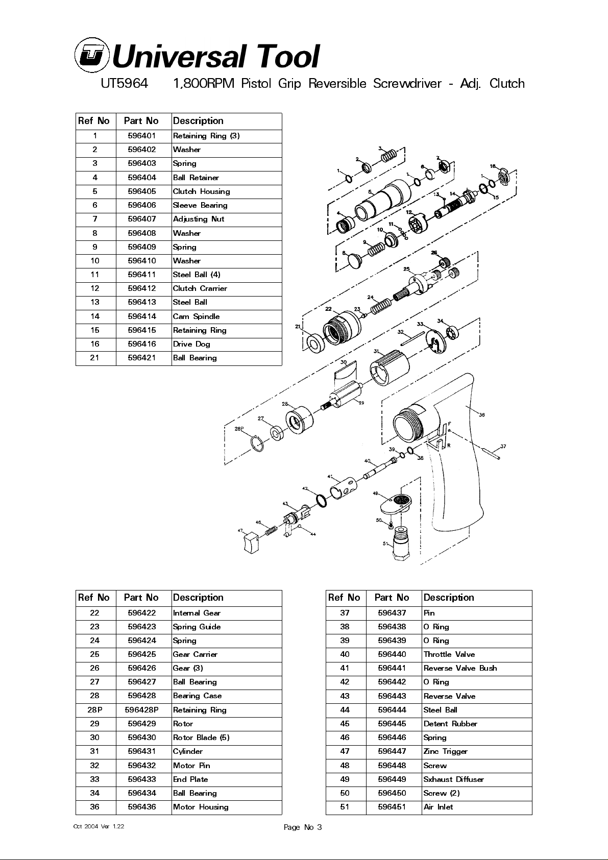
UT5964
1,800RPM Pistol Grip Reversible Screwdriver - Adj. Clutch
Ref No Part No Descripti on
1 596401 Retaining Ring (3)
2 596402 Washer
3 596403 Spring
4 596404 Ball Retainer
5 596405 Clutch Housing
6 596406 Sleeve Bearing
7 596407 Adjusting Nut
8 596408 Washer
9 596409 Spring
10 596410 Washer
11 596411 Steel Ball (4)
12 596412 Clutch Crarrier
13 596413 Steel Ball
14 596414 Cam Spindle
15 596415 Retaining Ring
16 596416 Drive Dog
21 596421 Ball Bearing
Ref No Part No Descripti on
22 596422 Internal Gear
23 596423 Spring Guide
24 596424 Spring
25 596425 Gear Carrier
26 596426 Gear (3)
27 596427 Ball Bearing
28 596428 Bearing Case
28P 596428P Retaining Ring
29 596429 Rotor
30 596430 Rotor Blade (5)
31 596431 Cylinder
32 596432 Motor Pin
33 596433 End Plate
34 596434 Ball Bearing
36 596436 Motor Housing
Oct 2004 Ver 1.22
Ref No Part No Description
37 596437 Pin
38 596438 O Ring
39 596439 O Ring
40 596440 Throttle Valve
41 596441 Reverse Valve Bush
42 596442 O Ring
43 596443 Reverse Valve
44 596444 Steel Ball
45 596445 Detent Rubber
46 596446 Spring
47 596447 Zinc Trigger
48 596448 Screw
49 596449 Sxhaust Diffuser
50 596450 Screw (2)
51 596451 Air Inlet
Page No 3
Page 4
Declaration of Conformity
Universal Air Tool Company Limited
Unit 8, Lane End Industrial Park, High Wycombe, Bucks, HP14 3BY, England
declare under our sole re sponsibility tha t the produc t
Model UT5964 Pistol Reversible Screwdriver, Serial Number
to which this declaration relates is in conformity with the following standard(s) or other normative document(s)
EN792 (Draft), EN292 Parts 1 & 2, ISO 8662 Parts 1 & 7, Pneurop PN8NTC1
following the provisions of
89/392/EEC as amended by 91/368/EEC & 93/44/EEC Directives
Lane End D.H.Moppett (Man. Director)
Place and date of issue Name and signature or equival ent marking of authorised
using the tool.
10) Use only correct spare parts . Do not improvise or make
temporary repairs.
11) Do not lock, tape, wire, etc. the on/off valve in the run
position. The trigger/lever etc. must always be free to return
to the 'off' position when it is rele ased.
12) Always shu t off the air supply to the tool, and depress
the trigger/lever etc. to exhaust air from the feed hose before
fitting, adjusting or removing the working attachment.
13) Check hose and fittings regularly for wear. Replace if
nece ssary. Do not carry the tool by its hose an d ensu re the
hand is rem ote from t he on/ off cont rol whe n carryin g the
tool with the air supply c onnected.
14) Take care against entanglement of moving parts of the
tool with clothing, ties, hair, cleaning rags, etc. This will
caus e the body to be drawn towards the tool and ca n be
very dan gerous.
15) It is expected that users will adopt safe working practices
and observ e all r ele va nt lega l requ irem ents wh e n in st alling,
using or maintain ing the t ool.
16) Do not install the tool unless an easily accessible and
easily operable on/ off valve is incorporate d in the air supply.
17) Take ca re tha t th e t ool exh au st air does n ot ca us e a
problem or blows on another pers on.
18) Never la y a tool down u nle ss th e working att ac hm en t
has stopped movin g.
19) Always en sure that the r everse button is in th e selected
position before startin g the tool.
20) Do not use bits or sockets with excessive wear to the
input and output drives. Make sure the bit, socket, extension
is firmly fixed to the tool.
21) When lo osenin g fasten ers fir st ensure that the re is
sufficient clearance behind the tool to avoid hand entrapment.
The to ol w i l l mo v e aw ay f r o m t h e t hreaded joint as the
nut/bolt is loosened and rides up the thread moving the
tool with it.
Notes
Distributor
Accessories
This document may not be copied wholly or in part by anyone without the consent of the Directors of Universal Air Tool
Designed & Written in the U.K.
©Copyright of Universa l Air Tool Company Limite d, established in the Un ited Kingdom, 1994
Page No 4
 Loading...