

Page 1
Includes - Foreseen Use, Work Stations, Putting Into Service, Operating,
Operator Instructions Important
Read these instructions carefully before installing, operating,
servicing or repairing this tool. Keep these instructions in a safe
Tel No
(01494) 883300
Vibration Level
Test Method
Tested in accordance with ISO
24.0
Test Method
Tested in accordance with Pneurop
test code PN8NTC1 and ISO Standard 3744
Dismantling, Assembly and Safety Rules
accessible place.
Manufacturer/Supplier Product Type
Universal Air Tool Company Limited
Unit 8
Lane End Industrial Park
High Wycombe
Bucks
Saw - Capacity 1.5mm
Stroke 10mm
Model No/Nos Serial No
UT5920 (UT8920A)
HP14 3BY
Fax No
(01494) 883237
Product Nett Weight
1.32
0.6 3/8 10 30 10
Recommended Working
Recommended Minimum
Maximum
Use - Safety Glasses
Use - Safety Gloves
Use - Safety Boots
Use - Breathing Masks
Use - Ear Protectors
lbs
Kg
Air Pressure
Personal Safety Equipment
Recommended Use Of
Balancer Or Support
No
bar
6.3
n/a
7.0
bar
bar
90
n/a
100
Yes
Recommended Hose Bore
Size - Minimum
Ins M/M Ft M
Noise Level
PSI
PSI
PSI
Sound Pressure Level 81.0 dB(A)
standards 8662 Parts 1 & 12
RPM
N/A
Cycles Per Min
10,000
Recommended Max.
Hose Length
Metres / Sec²
Foreseen Use Of The Tool
This tool is designed for the purpose of sawing materials when fitted
with the saw blades supplied by, or recommended by the
manufacturers. Do not use the tool for any other purpose than that
specified without consulting the manufacturer or the manufacturers
authorised representative. Do not modify the tool even for intended use
as a saw.
Work Stations
The tool should only be used as a handheld hand operated tool. It is
always recommended that the tool is used when standing on the solid
floor. It can be used in other positions but before any such use, the operator must be in a secure position having a firm grip and footing.
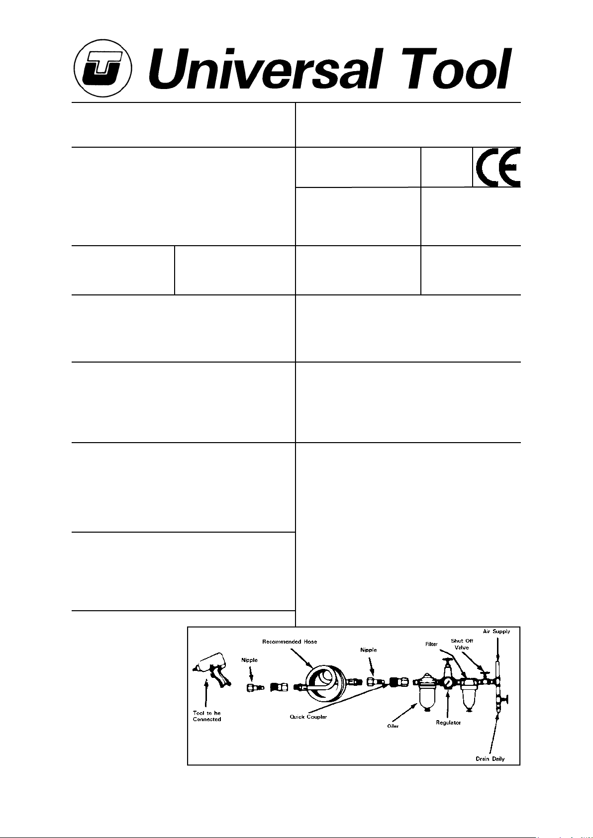
Putting Into Service
Air Supply
Use a clean lubricated air supply that
will give a measured air pressure at
the tool of 90 p.s.i./6.3 bar when the
tool is running with the trigger fully
depressed. Use recommended
hose size and length. It is recommended that the tool is connected
to the air supply as shown in figure 1.
Do not connect the tool to the air line
system without incorporating an
easy to reach and operate air shut off
valve. The air supply should be lubricated. It is strongly recommended
that an air filter, regulator, lubricator (FRL) is used as shown in Figure 1
as this will supply clean, lubricated air at the correct pressure to the tool.
Details of such equipment can be obtained from your supplier. If such
equipment is not used then the tool should be lubricated by shutting off
the air supply to the tool, depressurising the line by pressing the trigger
on the tool. Disconnect the air line and pour into the intake bushing a
teaspoonful (5ml) of a suitable pneumatic motor lubricating oil preferably incorporating a rust inhibitor. Reconnect tool to air supply and run
tool slowly for a few seconds to allow air to circulate the oil. If tool is used
frequently lubricate on daily basis and if tool starts to slow or lose power.
It is recommended that the air pressure at the tool whilst the tool is
running is 90 p.s.i./6.3 bar and this pressure should not be exceeded.
Page No 1
Page 2

Operating
To fit saw blade (35) first remove screw (38) and pull back cover (26).
Slacken 2 off screws (30) and push blade with the widest end into blade
chuck (33) as far as it will go and tighten 2 off screws (30), pull back
cover (26) and replace screw (38). Connect tool to suitable air supply.
Let the saw blade cut and never load the tool too heavily as this may
cause the blade to break. This tool has a high vibration level and should
only be used for short periods of time before resting.
Dismantling & Assembly Instructions
Disconnect tool from air supply.
Unscrew screw (38) until it is possible to pull back the chuck cover (26)
and note that screw (38) is held captive to the chuck cover (26) by a
spring washer. Tap in 2 off roll pins (44) to remove chuck cover (26).
Remove 2 off screws (30) and pull out blade (35). Remove 2 off screws
(24) and pull out work guide (34A) or (34B). Remove 2 off cap screws
(21). Remove 2 off screws (21) and remove upper wear shoe (39), 2 off
blade guides (40) and bridge plate (32). Remove screw (49). Ease
back spring (45) and grip the flats on the shaft on piston assembly (29)
and unscrew blade chuck (33) and remove spring (45). Unscrew inlet
bushing (9) and drive out pin (12) and take off lever (13).
Unscrew valve screw (1) and take out air controller (4) and O-rings (2)
and (3), spring (5) and valve stem (6) with O-ring (7). Do not remove
valve bushing (8) and O-ring (7A) unless a replacement is required.
Remove 4 off capscrews (10) with washers (11) and take off valve
block (23). Take off gaskets (48) and (22).
To dismantle piston assembly (29) grip with a spanner on the flats at the
front end and unscrew capscrew (21) with washer (20). Pull out piston
from valve case (15). Push actuate (19) from rear of valve case (15). Do
not remove valve sleeve (18) and pins from valve case (15). Pull out rear
bumper (43) from valve case (15). Cylinder (17) may be pressed out of
front end if the front bumper (42) needs to be replaced. Remove bush
(16) and gasket (47). Do not remove plastic sleeve (28A) from motor
housing (28) unless a replacement is required.
Reassembly
Clean all parts and examine for wear. Use only manufacturer or
authorised distributor supplied spare parts. Look for wear on seals and
bearings. Coat all parts with a pneumatic tool lubricating oil and
reassemble in the reverse order. Make sure that the saw blade is
correctly fitted.
not carry the tool by its hose and ensure the hand is remote from the
on/off control when carrying the tool with the air supply connected.
14) Take care against entanglement of moving parts of the tool with
clothing, ties, hair, cleaning rags, etc. This will cause the body to be
drawn towards the tool and can be very dangerous.
15) It is expected that users will adopt safe working practices and
observe all relevant legal requirements when installing, using or
maintaining the tool.
16) Do not install the tool unless an easily accessible and easily operable
on/off valve is incorporated in the air supply.
17) Take care that the tool exhaust air does not cause a problem or
blows on another person.
18) Never lay a tool down unless the working attachment has stopped
moving.
Safety Rules For A Saw
1) Read all the instructions before using this tool. All operators must be
fully trained in its use and aware of these safety rules.
2) Do not exceed the maximum working air pressure.
3) Use personal safety equipment.
4) Use only compressed air at the recommended conditions.
5) If the tool appears to malfunction remove from use immediately and
arrange for service and repair.
6) If the tool is used with a balancer or other support device ensure that
it is fixed securely.
7) Always keep hands away from the working attachment fitted to the
tool.
8) The tool is not electrically insulated. Never use the tool if there is any
chance of it coming into contact with live electricity.
9) Always when using the tool adopt a firm footing and/or position and
grip the tool firmly to be able to counteract any forces or reaction forces
that may be generated whilst using the tool.
10) Use only correct spare parts. Do not improvise or make temporary
repairs.
11) Do not lock, tape, wire, etc the on/off valve in the run position. The
trigger/lever etc must always be free to return to the 'off' position when
it is released.
12) Always shut off the air supply to the tool, and depress the
trigger/lever etc to exhaust air from the feed hose before fitting,
adjusting or removing the working attachment.
13) Check hose and fittings regularly for wear. Replace if necessary. Do
Page No 2
Page 3
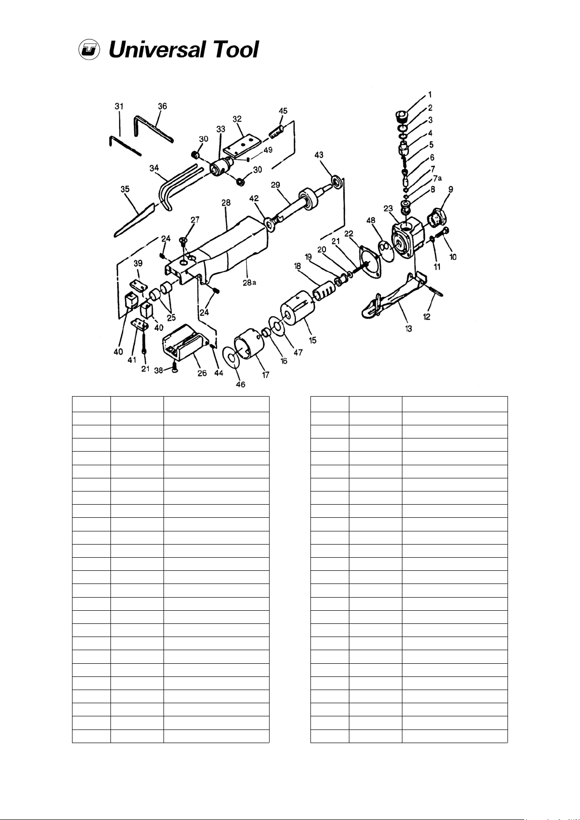
UT5920 Saw
Ref No Part No Description
1 0604001 Valve Screw
2 0604002 O-Ring
3 0604003 O-Ring
4 0604004 Air Controller
5 0604005 Valve Spring
6 0604006 Valve Stem
7,7A 0604007 O-Ring
8 0604008 Valve Bushing
9 0604009 Inlet Bushing
10 0604010 Cap SCrew (4)
11 0604011 Washer
12 0604012 Lever Pin
13 0604013 Throttle Lever
15 0604015 Valve Case
16 0604016 Bush
17 0604017 Cylinder
18 0604018 Valve Sleeve
19 0604019 Actuator Valve
20 0604020 Washer
21 0604021 Cap Screw (2)
22 0604022 Gasket
23 0604023 Valve Block
24 0604024 Set Screw (2)
25 0604025 Bush (2)
26 0604026 Chuck Cover
Feb 2008 Ver 1.23
Ref No Part No Description
27 0604027 Screw (2)
28 0604028 Housing
28A 0604028A Plastic Sleeve
29 0604029 Piston Assembly
30 0604030 Set Screw (2)
31 0604031 Service Wrench (2mm)
32 0604032 Guide Plate
33 0604033 Blade Chuck
34A 0604034 Work Guide (Long)
34B 0604034B Work Guide (Short)
35A 0604035 Blade (32T)
35B 0604035B Blade (24T)
36 0604036 Service Wrench (4mm)
38 0604038 Screw
39 0604039 Upper Wear Shoe
40 0604040 Blade Guide (2)
41 0604041 Bridge
42 0604042 Front Bumber
43 0604043 Rear Bumper
44 0604044 Roll Pin (2)
45 0604045 Spring
46 0604046 Gasket
47 0604047 Gasket
48 0604048 Gasket
49 0604049 Set Screw
Page No 3
Page 4
Accessories
Declaration of Conformity
Universal Air Tool Company Limited
Unit 8, Lane End Industrial Park, High Wycombe, Bucks, HP14 3BY, England
declare under our sole responsibility that the product
Model UT5920 (UT8920A) Saw, Serial Number
to which this declaration relates is in conformity with the following standard(s) or other normative document(s)
EN792 (Draft), EN292 Parts 1 & 2, ISO 8662 Parts 1 & 12, Pneurop PN8NTC1
following the provisions of
89/392/EEC as amended by 91/368/EEC & 93/44/EEC Directives
Lane End D.H.Moppett (Man. Director)
Place and date of issue Name and signature or equivalent marking of authorized person
Notes
Distributor
This document may not be copied wholly or in part by anyone without the consent of the Directors of Universal Air Tool Company Limited
Designed & Written in the U.K.
©Copyright of Universal Air Tool Company Limited, established in the United Kingdom, 1994
Page No 4
 Loading...