

Page 1
Operator Instructions
t
Includes - Foreseen Use, Work Stations, Putting Into Service,
Operating, Dismantling, Assembly and Safety Rules
Important
Read these instructions carefully before insta lling, operating,
servicing or repairing this tool. Keep these instructions in a safe
accessible place.
Manufacturer/Supplier Product Type
Universal Air Tool Company Limited
20mm Belt Sander
Unit 8
Lane End Industrial Park
High Wycombe
Bucks
Model No/Nos Serial No (if any)
UT5765
HP14 3BY
Tel No Fax No
(01494) 883300 (01494) 883237
RPM
16,000
Cycles Per Min
Product Nett Weight
2.53
1.15 3/8 10 30 10
Recommended Working
Recommended Minimum
Maximum
Use - Safety Glasses
Use - Safety Gloves
Use - Safety Boots
Use - Breathing Masks
lbs
Kg
Air Pressure
Perso n a l Sa fe t y E q ui pm en t
Recommended Use Of
Balancer Or Support
No
6.3
bar
90
PSI
n/a
7.0
bar
bar
Yes
Yes
n/a
100
PSI
PSI
Recommended Hose Bore
Size - Minimum
Ins M/M Ft M
Noise Level
Sound Pressure Level 84.7 dB(A)
Sound Power Level 95.8 dB(A)
Test Method
Tested in accordance with Pneurop
est code PN8NTC1 and ISO Standard 3744
Vibration Level
Test Method
Less than 2.5
Tested in accordance with ISO
standard 8662/1
Recommended Max.
Use - Ear Protectors
Foreseen Use of the Tool
The tool is designed for the purpose of cleaning or sanding of
materials using a continuous abrasive belt. Belts are available in
various grades to suit fine finishing or fast material removal.
Do not use the tool for any other purpose than that for which it
was designed. Do not modify this tool for any other use or for
its use as a belt sander without first consulting the manufacturer
or the manufacturer’s authorised distributor.
Work Stations
The tool should only be used as a hand held hand operated tool.
It is always recommended that the tool is used when standing
on a solid floor. It can be used in other positions but before any
such use the operator must be in a secure position having a firm
grip and footing and be aware of the safety rules to be obeyed
when using the sander.
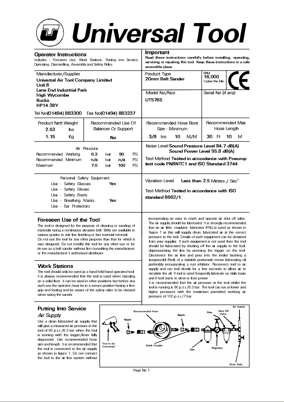
incorporating an easy to reach and operate air shut off valve.
The air supply should be lubricated. It is strongly recommended
that an air filter, regulator, lubricator (FRL) is used as shown in
Figure 1 as this will supply clean, lubricated air at the correct
pressure to the tool. Details of such equipment can be obtained
from your supplier. If such equipment is not used then the tool
should be lubricated by shutting off the air supply to the tool,
depressu rising the line by pressing th e trigger on the tool.
Disconne c t th e a ir line an d pour into the in ta ke bu sh ing a
teaspoonful (5ml) of a suitable pneumatic motor lubricating oil
preferably incorporating a rust inhibitor. Reconnect tool to air
supply an d run tool slowly for a fe w seconds to allow a ir to
circulate the oil. If tool is used frequently lubricate on daily basis
and if tool starts to slow or lose power.
It is recommended that the air pressure at the tool whilst the
tool is running is 90 p.s.i./6.3 bar. The tool can run at lower and
higher pressures with the maximum permitted working air
pressure of 100 p.s.i./7 bar.
Hose Length
Metres / Sec²
Putting Into Service
Air Supply
Use a clean lubricated air supply that
will give a measured air pressure at the
tool of 90 p.s.i./6.3 bar when the tool
is runn ing with the trigger/le ver fully
depressed. Use recommended hose
size and length. It is recommended that
the tool is connected to the air supply
as shown in figure 1. Do not connect
the tool to the air line system without
Page No 1
Page 2
Operating
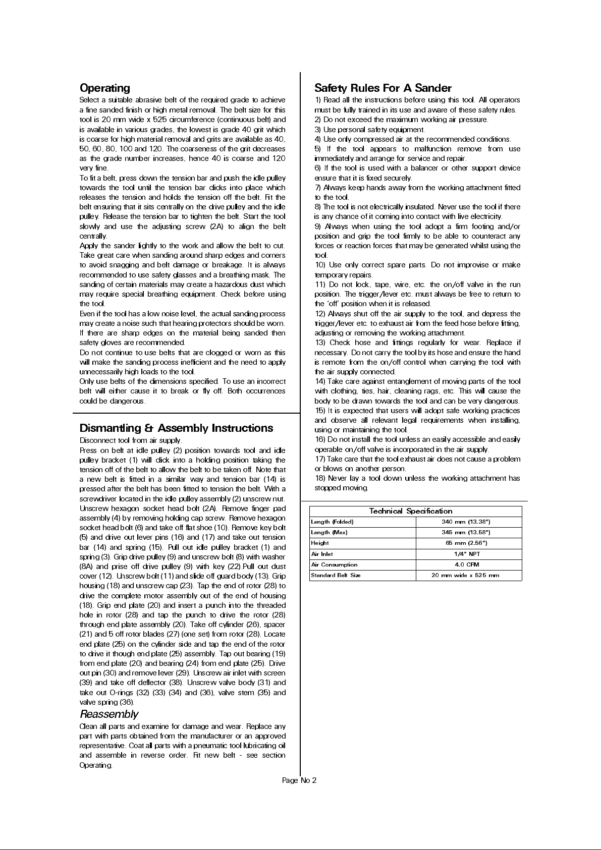
Select a suitable abrasive belt of the required grade to achieve
a fine sanded finish or high metal removal. The belt size for this
tool is 20 mm wide x 525 circumference (continuous belt) and
is available in various grades, the lowest is grade 40 grit which
is coarse for high material removal and grits are available as 40,
50, 60, 80, 100 and 120. The coarseness of the grit decreases
as the grade number increases, hence 40 is coarse and 120
very fine.
To fit a belt, press down the tension bar and push the idle pulley
towards th e tool until the te nsion bar clicks into place which
releases the tension and holds the tension off the belt. Fit the
belt ensuring that it sits centrally on the drive pulley and the idle
pulley. Release the tension bar to tighten the belt. Start the tool
slowly and use the adjusting screw (2A) to align the belt
centrally.
Apply the sander lightly to the work and allow the belt to cut.
Take great care when sanding around sharp edges and corners
to avoid snagging and belt damage or breakage. It is always
recommended to use safety glasses and a breathing mask. The
sanding of certain materials may create a hazardous dust which
may require special breathing equipment. Check before using
the tool.
Even if the tool has a low noise level, the actual sanding process
may create a noise such that hearing protectors should be worn.
If there a re sharp edges on th e material being sa nded then
safety gloves are recommended.
Do not continue to use belts that are clogged or worn as this
will make the sanding process inefficient and the need to apply
unnecessarily high loads to the tool.
Only use belts of the dimensions specified. To use an incorrect
belt will either cause it to break or fly off. Both occurrences
could be dangerous.
Dismantling & Assembly Instructions
Disconnect tool from air supply.
Press on belt at idle pulley (2) position towards tool and idle
pulley brac ket (1) will click into a holding position tak ing the
tension off of the belt to allow the belt to be taken off. Note that
a ne w belt is fitted in a s imilar way an d tension bar (14) is
pressed after the belt has been fitted to tension the belt. With a
screwdriver located in the idle pulley assembly (2) unscrew nut.
Unscre w hexagon sock et head bolt (2A). Remove finge r pad
assembly (4) by removing holding cap screw. Remove hexagon
socket head bolt (6) and take off flat shoe (10). Remove key bolt
(5) and drive out lever pins (16) and (17) and take out tension
bar (14) and spring (15). Pull out idle pulley bracket (1) and
spring (3). Grip drive pulley (9) and unscrew bolt (8) with washer
(8A) and prise off drive pulley (9) with k ey (22).Pull out dust
cover (12). Unscrew bolt (11) and slide off guard body (13). Grip
housing (18) and unscrew cap (23). Tap the end of rotor (28) to
drive the complete motor assembly out of the end of housing
(18). Grip end plate (20) and insert a punch into the threaded
hole in rotor (28) and tap the punch to drive the rotor (28)
through end plate assembly (20). Take off cylinder (26), spacer
(21) and 5 off rotor blades (27) (one set) from rotor (28). Locate
end plate (25) on the cylinder side and tap the end of the rotor
to drive it though end plate (25) assembly. Tap out bearing (19)
from end plate (20) and bearing (24) from end plate (25). Drive
out pin (30) and remove lever (29). Unscrew air inlet with screen
(39) and take off deflector (38). Unscrew valve body (31) and
take out O-rings (32) (33) (34) and (36), valve stem (35) and
valve spring (36).
Reassembly
Clean all parts and examine for damage and wear. Replace any
part with parts obtained from the manufacturer or an approved
representative. Coat all parts with a pneumatic tool lubricating oil
and assemble in reverse order. Fit new belt - see section
Operating.
Page No 2
Safety Rules For A Sander
1) Read all the instructions before using this tool. All operators
must be fully trained in its use and aware of these safety rules.
2) Do not exceed the maximum working air pressure.
3) Use personal safety equipment.
4) Use only compressed air at the recommended conditions.
5) I f the too l appea rs to mal functio n remove f rom use
immediately and arrange for service and repair.
6) If the tool is used with a balancer or other support device
ensure that it is fixed securely.
7) Always keep hands away from the working attachment fitted
to the tool.
8) The tool is not electrically insulated. Never use the tool if there
is any chance of it coming into contact with live electricity.
9) Always when u sing the tool a dopt a firm footing and/or
position and grip the tool firmly to be able to counteract any
forces or reaction forces that may be generated whilst using the
tool.
10) Use only correct spare parts . Do not improvise or make
temporary repairs.
11) Do not lock, tape, w ire, etc. the on/off va lve in the run
position. The trigger/lever etc. must always be free to return to
the ‘off’ position when it is released.
12) Always shut off the air supply to the tool, and depress the
trigger/lever etc. to exhaust air from the feed hose before fitting,
adjusting or removing the working attachment.
13) Check hose and fittings regularly for wear. Replace if
necessary. Do not carry the tool by its hose and ensure the hand
is remote from the on/off control when carrying the tool with
the air supply connected.
14) Take care against entanglement of moving parts of the tool
with clothing, ties, hair, cleaning rags, etc. This will cause the
body to be drawn towards the tool and can be very dangerous.
15) It is expected that users will adopt safe working practices
and observ e all r ele va nt lega l requ irem ents wh e n in st alling,
using or maintaining the tool.
16) Do not install the tool unless an easily accessible and easily
operable on/off valve is incorporated in the air supply.
17) Take care that the tool exhaust air does not cause a problem
or blows on another person.
18) Never lay a tool down unless the working attachment has
stopped moving.
Technical Specification
Lengt h (Folded) 340 mm (13.38" )
Lengt h (Max) 345 mm (13.58" )
Height 65 mm (2. 56")
Air I nlet 1/4" NPT
Air C onsumption 4.0 CF M
Standa rd Belt Size 20 mm wide x 525 mm
Page 3
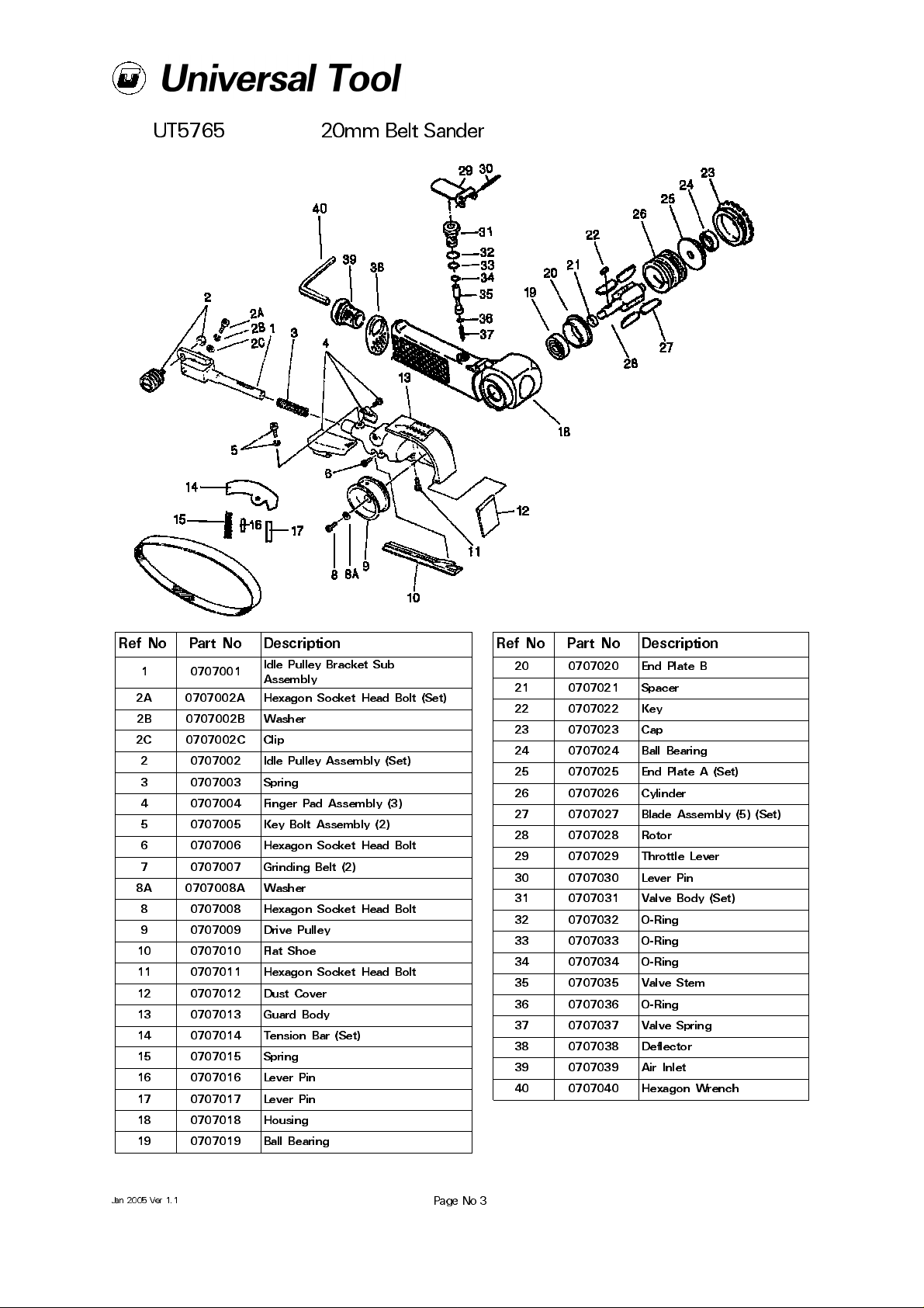
UT5765 20mm Belt Sander
Ref No Part No Description
1 0707001
2A 0707002A Hexagon Socket Head Bolt (Set)
2B 0707002B Washer
2C 0707002C Clip
2 0707002 Idle Pulley Assembly (Set)
3 0707003 Spring
4 0707004 Finger Pad Assembly (3)
5 0707005 Key Bolt Assembly (2)
6 0707006 Hexagon Socket Head Bolt
7 0707007 Grinding Belt (2)
8A 0707008A Washer
8 0707008 Hexagon Socket Head Bolt
9 07070 09 Drive P ulley
10 0707010 Flat Shoe
11 0707011 Hexagon Socket Head Bolt
12 0707012 Dust Cover
13 0707013 Guard Body
14 0707014 Tension Bar (Set)
15 0707015 Spring
16 0707016 Lever Pin
17 0707017 Lever Pin
18 0707018 Housing
19 0707019 Ball Bearing
Idle Pulley Bracket Sub
Assembly
Ref No Part No Description
20 0707020 End Plate B
21 0707021 Spacer
22 0707022 Key
23 0707023 Cap
24 0707024 Ball Bearing
25 0707025 End Plate A (Set)
26 0707026 Cylinder
27 0707027 Blade Assembly (5) (Set)
28 0707028 Rotor
29 0707029 Throttle Lever
30 0707030 Lever Pin
31 0707031 Valve Body (Set)
32 0707032 O-Ring
33 0707033 O-Ring
34 0707034 O-Ring
35 0707035 Valve Stem
36 0707036 O-Ring
37 0707037 Valve Spring
38 0707038 Deflector
39 0707039 Air Inlet
40 0707040 Hexagon Wrench
Jan 2005 Ver 1.1
Page No 3
Page 4
Declaration of Conformity
Universal Air Tool Company Limited
Unit 8, Lane End Industrial Park, High Wycombe, Bucks, HP14 3BY, England
declare under our sole responsibility that the product
Model UT5765 20mm Belt Sander, Serial Number
to which this declaration relates is in conformity with the following standard(s) or other normative document(s)
EN792 (Draft), EN292 Parts 1 & 2, ISO 8662 Part 1, Pneurop PN8NTC1
following the provisions of
89/392/EEC as amended by 91/368/EEC & 93/44/EEC
Lane End D.H.Moppett (Man Director)
Place and date of issue Name and signature or equivalent marking of authorised person
Accessories
Notes
Distributor
This document may not be copied wholly or in part by anyone without the consent of the Directors of Universal Air Tool Company Limited
Designed & Written in the U.K.
©Copyright of Universal Air Tool Company Limited, established in the United Kingdom, 1994
Page No 4
 Loading...