

Page 1
T
Operator Instructions Important
T
V
T
Includes - Foreseen Use, Work Stations, Putting Into Service,
Operating, Dismantling, Assembly and Safety Rules
Manufacturer/Supplier Product Type
Universal Air Tool Company Limited
Unit 8
Lane End Industrial Park
High Wycombe
Bucks
HP14 3BY
el No Fax No(01494) 883300 (01494) 883237
Read these instructions carefully before installing, operating,
servicing or repairing this tool. Keep these instructions in a
safe accessible place.
Die Grinder
1/4” Capacity
Model No/Nos Serial No (if any)
UT5720A
RPM
22,000
Cycles Per
Product Nett Weight
1.23
0.62 3/8 10 30 10
lbs
Kg
Recommended Use Of
Balancer Or Support
No
Air Pressure
Recommended Working
Recommended Minimum
Maximum
6.3
n/a
7
bar
bar
bar
90
n/a
100
Personal Safety Equipment
Use - Safety Glasses
Use - Safety Gloves
Yes
Yes
Use - Safety Boots
Use - Breathing Masks
Use - Ear Protectors
Yes
Yes
Foreseen Use Of The Tool
This die grinder is primarily designed for use with bonded
abrasive mounted point grinding wheels. It may also be used
with steel rotary files and carbide burrs provided their speed
rating matches the speed of the grinder.
This tool should not be fitted with cutting off wheels, saw
blades, drill bits, etc. If there is any doubt about the correct
use of this product contact your supplier for advice.
Also make sure that the shank size of the attachment to be
driven matches with the collet size fitted in the grinder and
that the maximum allowed running speed of the attachment
exceeds that marked on the grinder.
There are special rules governing the use of bonded abrasive
mounted point grinding wheels - for details see section
"Operating".
Recommended Hose Bore
Recommended Max.
Size - Minimum
Ins M/M Ft M
Noise Sound Pressure Level 86.0 dB(A)
PSI
PSI
est Method Tested in accordance with
Pneurop test code PN8NTC1 and ISO
Sound Power Level 99.0 dB(A)
PSI
ibration
Less than 2.5
est Method Tested in accordance with ISO
standard 8662/1 & 8662/17
Putting Into Service
Air Supply
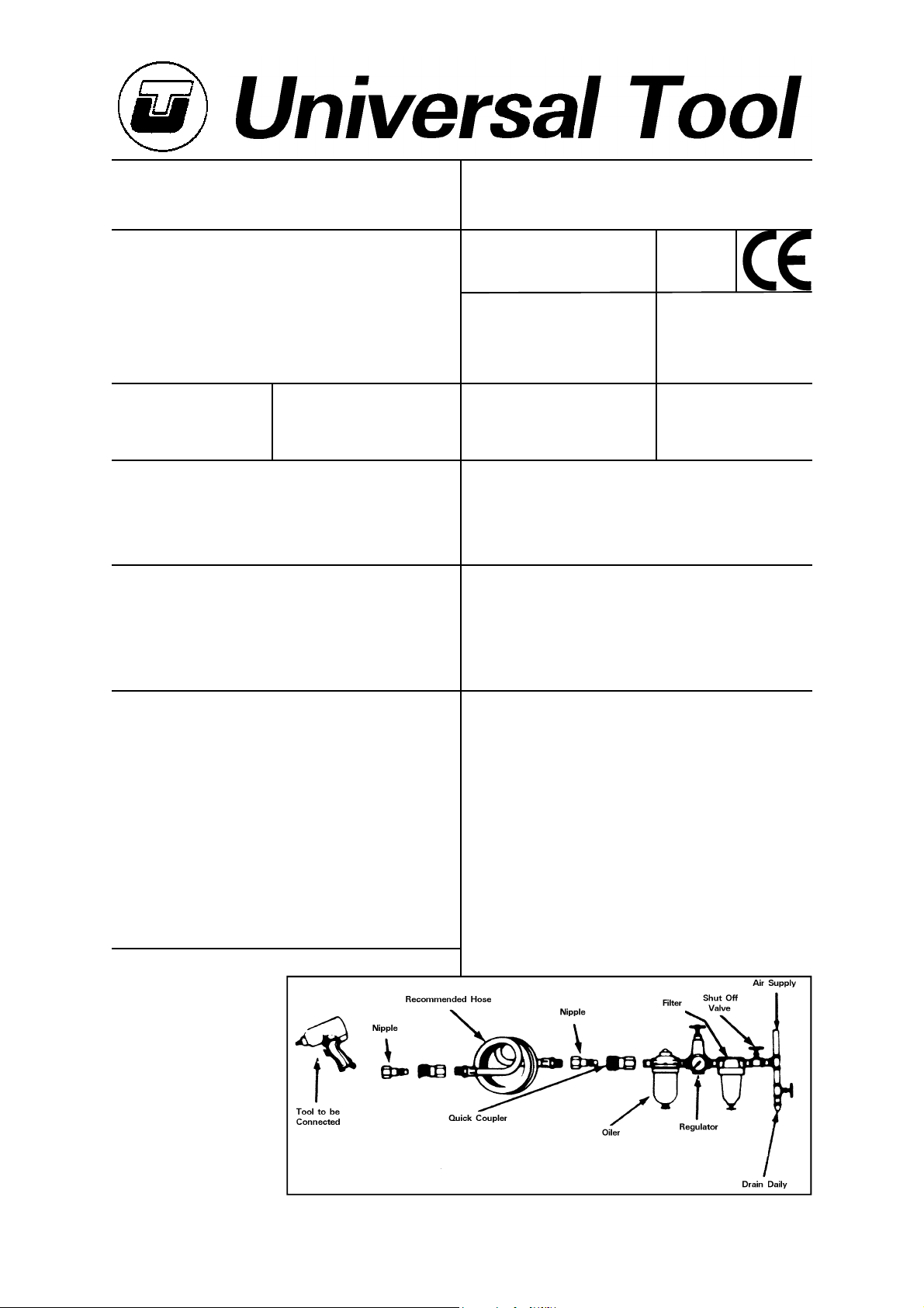
Use a clean lubricated air supply that will give a measured
air pressure at the tool of 90 p.s.i./6.3 bar when the tool
is running with the lever/trigger fully depressed. Use
recommended hose size and length. It is recommended that
the tool is connected to the air supply as shown in figure
1. Do not connect the tool to the air line system without
incorporating an easy to reach and operate air shut off valve.
The air supply should be lubricated. It is strongly
recommended that an air filter, regulator, lubricator (FRL) is
used as shown in Figure 1 as this will supply clean, lubricated
air at the correct pressure to the tool. Details of such
equipment can be obtained from your supplier. If such
equipment is not used then the tool should be lubricated by
shutting off the air supply to the tool, depressurising the line
Metres / Sec²
Work Stations
The tool should only be used
as a handheld hand operated
tool. It is always recommended that the tool is used
when standing on the solid
floor. It can be used in other
positions but before any such
use, the operator must be in
a secure position having a firm
grip and footing and be aware
of the extra safety precautions
that must be observed when
using Grinding Machines.
Hose Length
Page No 1
Page 2
by pressing the lever/trigger on the tool. Disconnect the air
line and pour into the intake bushing a teaspoonful (5ml) of
a suitable pneumatic motor lubricating oil preferably
incorporating a rust inhibitor. Reconnect tool to air supply
and run tool slowly for a few seconds to allow air to circulate
the oil. If tool is used frequently lubricate on daily basis and
if tool starts to slow or lose power.
It is recommended that the air pressure at the tool whilst
the tool is running is 90 p.s.i./6.3 bar. The tool can run at
lower and higher pressures with the maximum permitted
working air pressure of 100 p.s.i./7.0 bar.
Operating
Select a suitable mounted point that has a free running speed
higher than the maximum running speed marked on the tool.
Make sure that the diameter of the shank exactly matches
the diameter of the collet mounted in the grinder. There are
four standard sizes of collet available for use with this grinder,
i.e.
1) - 1/4" dia (0.250ins)(6.35mm)
2) - 6mm (0.236ins)
3) - 1/8" (0.125ins)(3.175mm)
4) - 3mm (0.118ins)
* available to order 2mm, 2.5mm, 3.5mm and 5mm diameter
collets
Never try to force a 1/4" diameter shank into a 6mm collet
or a 1/8" diameter shank into a 3mm collet. Never try to
close a 1/4" diameter collet to secure a 6mm shank or a
1/8" diameter collet to secure a 3mm diameter shank.
Always match correctly the shank size to the collet size. If
uncertain, have parts measured by a competent person.
Push the shank as far as possible into the collet and tighten
the collet nut using the spanners provided on the collet nut
and output spindle.
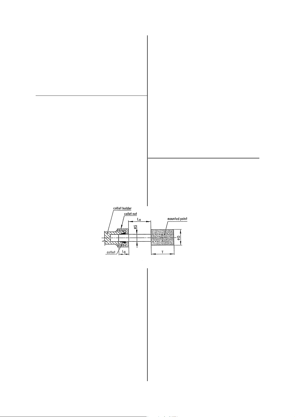
The shank of the mounted point
may be pulled forward from the
maximum insertion length but
always ensure a minimum gripping
length of not less than 10mm See Figure 2.
Be aware that the allowed running
speed of the mounted point is
lowered because of an increase in
the length of the shank between
the end of the collet and the
body of the mounted point.
This distance is shown in
Diagram 2 as "LO" and is called the overhang. The
information with respect to mounted point size, permissible
running speed and reduction in running speed due to an
increase in overhang is available from the supplier of the
mounted point.
If the increase in overhang for access reasons takes the
permissible running speed of the mounted point below the
free running speed of the grinder select a smaller diameter
mounted point.
The fitting of the mounted point should be done by a trained
operator.
When first starting the grinder with a new wheel fitted, the
grinder should not be near other persons and be held in a
protected area, i.e. under a bench and run for a few seconds.
This will protect personnel from possible effects of damage
to the mounted point before it was fitted to the grinder i.e.
wheel breakage.
Always use eye protection and wear protective gloves if
there are sharp edges in the work area. The tool and the
grinding process can create a noise level such that the use
of ear protectors is advised.
If the grinding process creates a dust then use a suitable
Figure 2. Gripping length of collet and
Page No 2
breathing mask.
Check that the material being worked will not cause harmful
dust or fumes. If this is so then special breathing masks
may be required.
If the grinder vibrates when first fitting a mounted point or
during operation, remove from service immediately and
correct fault before continuing to use.
Do not apply excessive pressure as this will reduce the
cutting efficiency and can bend the shank of the mounted
point causing vibration and the possibility of breakage. Apply
light loads to allow the wheel to cut.
Handle the grinder with care. If the grinder is dropped,
carefully check the mounted point for damage, i.e. cracks,
chipping and start for the first time as for fitting a new wheel
i.e. under a bench.
Never exceed the maximum air pressure. If there is this
possibility always use this grinder with a pressure reducing
valve fitted in the supply line. Your supplier will advise of
suitable equipment.
This grinder is fitted with a speed regulator and the speed
may be reduced by rotating air regulator(4) with a suitable
screwdriver. When making speed checks always rotate the
air regulator to the position to give the highest maximum
speed.
Dismantling & Assembly Instructions
Disconnect tool from air supply.
Remove collet nut (32) and collet (31) from spindle (27).
Unscrew housing cap (30) and hold tool in a vice on flats
of retainer (29). Unscrew inlet bushing (34) and filter screen
(13). Remove circlip (12) and pull out exhaust deflector (11).
Remove grinder from vice and locate on flats at air inlet end
of motor housing (10). Tap out pin (8) and remove safety
lever. Do not dismantle safety lever
unless replacement parts are required.
Unscrew retainer (29) and pull out
D = diameter of mounted point
T = length of mounted point
Lo = overhang
S = diameter of shank
Lg = gripping length
motor and spindle assembly. To
dismantle, grip motor assembly tightly
by hand and tap the rear end small
diameter of the rotor through the rear end plate (16) and
bearing (15). Remove cylinder (18) and 4 off rotor blades
(19). Grip the rotor in soft jaws and unscrew spindle (27)
from rotor(20). The rotor (20) and bearing spacer (21) may
be pulled or tapped clear from front end plate (23), shims
(25) if fitted and ball bearing (26).
Unscrew valve screw (1) complete with O-Ring (2) using a
wide blade screwdriver and pull out air regulator (4), O-Ring
(3), spring (5), O-Ring (6) and throttle valve(7).
Clean and examine parts for wear and replace only with
manufacturer supplied parts.
Ensure that the faces of end plates (23) and (16) that abut
cylinder (18) are flat and free from burrs. Lap on a flat fine
grade of abrasive paper if necessary. Lightly coat parts with
oil, pack bearings with a lithium or molybdenum based grease
and reassemble in the reverse order.
Reassembly
Note: When reassembling motor assembly, ensure that pins
(17) in the faces of end plates (16) and (23) locate in cylinder
(18) and that pin (22) in the outer diameter of front end
plate (23) locates in the slot of motor housing (10).
Check the collet assembly the function of the safety lever
Page 3
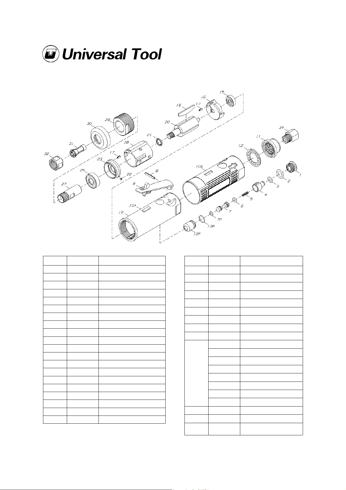
UT5720A Rear Exhaust Die Grinder
Ref No Part No Description
1 729262 Valve Screw
2 729073 O-Ring
3 729088 O-Ring
4 729282 Air Regulator
5 729258 Spring
6 1012370 O-Ring
7 729259 Throttle Valve
7P 729259P O-Ring
8 729167 Throttle Lever Pin
9 729264 Locking Lever
10A 729701A Motor Housing
10S 729701S Housing Sleeve
10P 729701P Valve Bushing
10R 729701R O-Ring (for 10P Bushing)
11 729702 Exhaust Deflector
12 729703 Circlip
15 1010183 Ball Bearing
16 729706 Rear Plate
17 729707 Pin (2)
18 729708 Cylinder
Ref No Part No Description
19 729709 Rotor Blades (4)
20 729710 Rotor
21 729711 Bearing Spacer
22 729707P Pin
23 729712 Front End Plate
26 729113 Ball Bearing
27 729715 Spindle
29 729717 Retainer
30 729718 Housing Cap
92253 1/4" Collet
92232 1/8" Collet
732222 2.0mm Collet
31
32 729719 Collet Nut
34 732449 Inlet Bushing
732223 2.5mm Collet
732224 3.0mm Collet
732225 3.5mm Collet
732226 5.0mm Collet
732227 6.0mm Collet
732248
Collet Wrench (2)
(Not Shown)
Sep 2003 Ver 1.0
Page No 3
Page 4
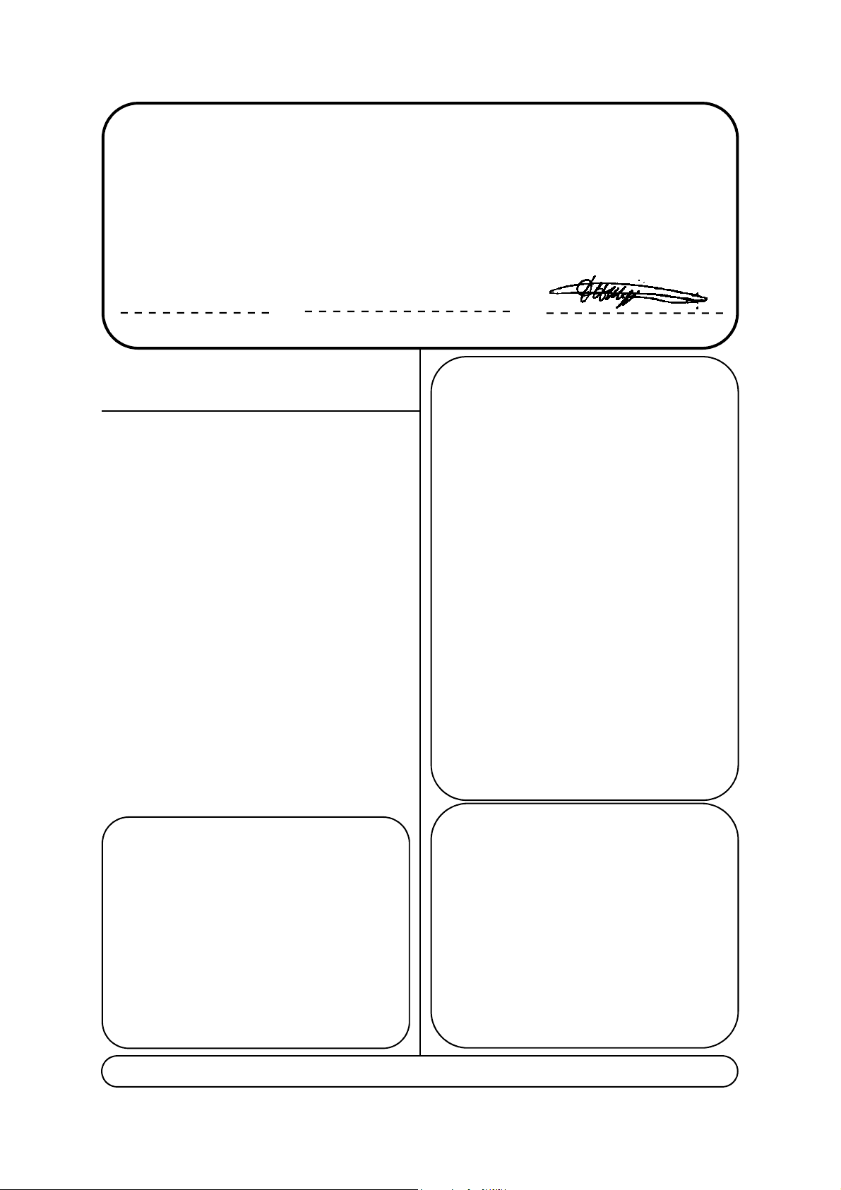
Declaration of Conformity
A
Universal Air Tool Company Limited
Unit 8, Lane End Industrial Park, High Wycombe, Bucks, HP14 3BY, England
declare under our sole responsibility that the product
Model UT5720A Die Grinder, Serial Number
to which this declaration relates is in conformity with the following standard(s) or other normative document(s)
EN792 (Draft), EN292 Parts 1 & 2, ISO 8662 Parts 1 & 17, Pneurop PN8NTC1
following the provisions of
89/392/EEC as amended by 91/368/EEC & 93/44/EEC
Lane End D.H.Moppett (Man. Director)
Place and date of issue Name and signature or equivalent marking of authorised
and that the free speed is correct before returning to service.
Ensure that the air regulator is in the maximum open position
before making speed check.
Safety Rules When Using A Die
Grinder
1) Read all the instructions before using this tool. All operators
must be fully trained in its use and aware of these safety
rules.
2) Always select suitable abrasive to use with this tool - see
Operating Instructions.
3) Always shut off the air supply to the grinder and depress
the lever to exhaust air from the feed hose before fitting,
adjusting or removing the mounted point.
4) Always adopt a firm footing and/or position before using
the grinder.
5) Use only correct spare parts.
6) Check hose and fittings regularly for wear. Do not carry
the tool by its hose.
7) Do not remove and never tie down the safety lever.
8) Never exceed the maximum air pressure and check the
free running speed frequently. Have air regulator fully open
when making speed checks.
9) Use safety equipment as recommended.
10) Take care against entanglement of moving parts of the
tool with clothing, ties, hair, cleaning rags, etc.
11) Use only compressed air at the recommended pressure.
12) Do not attempt to fit any other attachment than those
recommended - see "Foreseen Use of Tool".
13) If the tool appears to malfunction, remove from use
immediately, and arrange for service and repair.
Notes
ccessories
This document may not be copied wholly or in part by anyone without the consent of the Directors of Universal Air Tool
Designed & Written in the U.K.
©Copyright of Universal Air Tool Company Limited, established in the United Kingdom, 1994
Page No 4
Distributor
 Loading...