

Page 1
Operator Instructions
T
V
T
T
Includes - Foreseen Use, Work Stations, Putting Into Service,
Operating, Dismantling, Assembly and Safety Rules
Important
Read these instructions carefully before installing, operating,
servicing or repairing this tool. Keep these instructions in a
safe accessible place.
Manufacturer/Supplier Product Type
Universal Air Tool Company Limited
Unit 8
Lane End Industrial Park
High Wycombe
Bucks
HP14 3BY
el Fax (01494) 883300 (01494) 883237
Dual Action Sander 6”(150mm) Pad
Model No/Nos Serial No
UT3 (HLC3)
UT3DC with Dust
Control (HLC3DC)
RPM
10,000
Cycles Per
Product Nett Weight
3.96 (Non DC) 4.18 (DC)
1.8 (Non DC) 1.9 (DC)
lbs
Kg
Recommended Use Of
Balancer Or Support
No
Air Pressure
Recommended Working
Recommended Minimum
Maximum
6.3
n/a
7.0
bar
bar
bar
90
n/a
100
Personal Safety Equipment
Use - Safety Glasses
Yes
Use - Safety Gloves
Use - Safety Boots
Use - Breathing Masks
Yes
Use - Ear Protectors
Foreseen Use of Tool
This tool is designed for the purpose of cleaning or sanding
of a variety of materials typically metal, wood, plastic
materials, etc. The dual rotary orbital action reduces the
amount of abrasive grinding marks and hence is primarily a
finishing sanding tool. It can be used with a variety of grades
of 150 mm (6” diameter) abrasive discs which, according
to pad fitted to the tool, can be self adhesive or Velcro
attached. If fitted to the dust collecting system this should
always be used. The system may be integral or required to
be fixed to an external vacuum source.
The machine fitted with dust collection should not be used
with water. If use with water is required, water can act as
a dust suppressor and the dust collector would not be
required.
Do not use the tool for any other purpose to that for which
it has been designed and use only abrasive discs as described.
Do not modify the tool for any other use or for its use as
a sander without first consulting the manufacturer or his
authorised distributor.
Recommended Hose Bore
Recommended Max.
Size - Minimum
Ins M/M Ft M
3/8 10 30 10
Noise Sound Pressure Level 86.8 dB(A)
PSI
PSI
PSI
est Method Tested in accordance with
Pneurop test code PN8NTC1 and ISO
ibration
Sound Power Level 97.6 dB(A)
5.1
est Method Tested in accordance with ISO
standards 8662 Parts 1 & 8
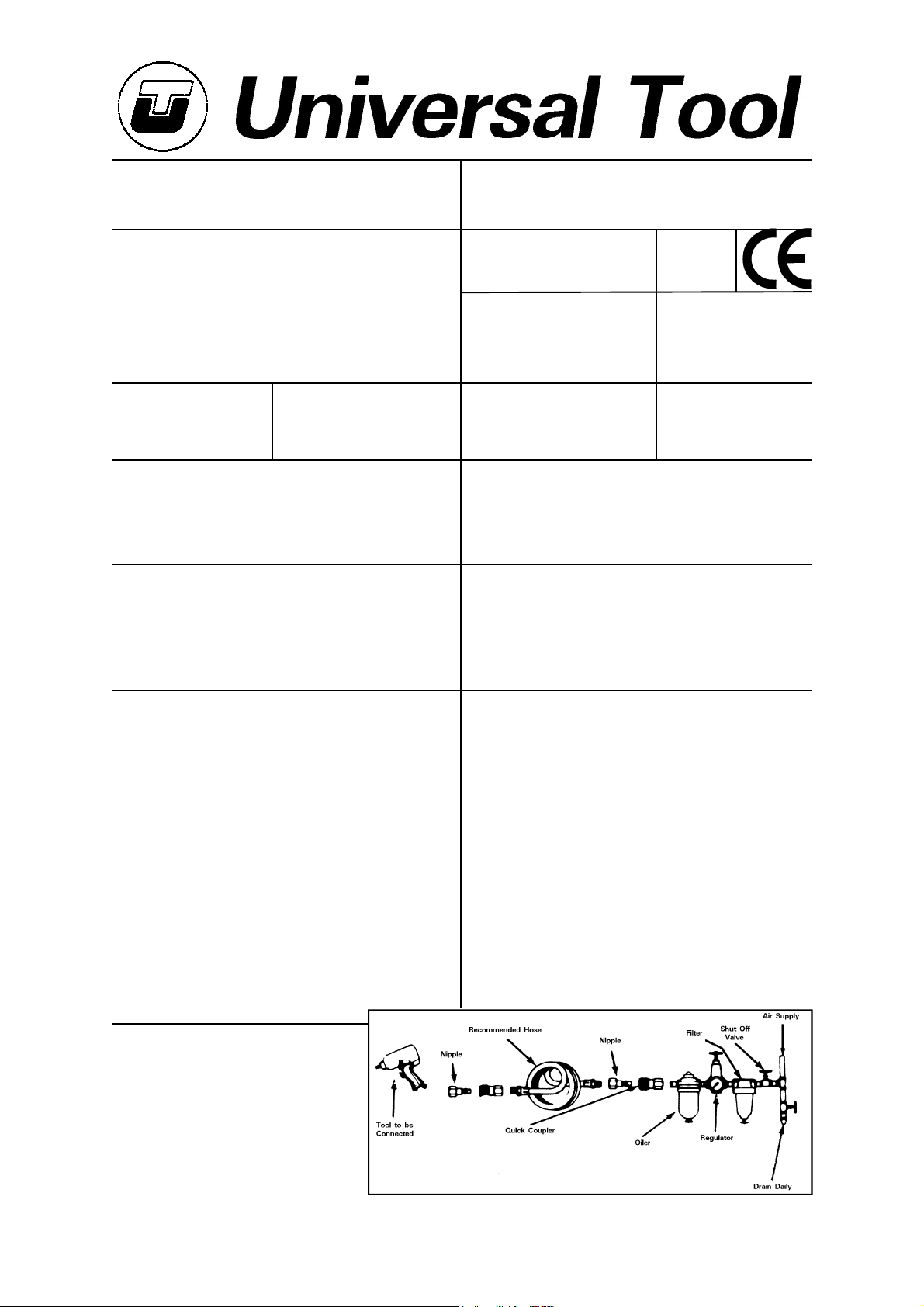
Putting Into Service
Air Supply
Use a clean lubricated air supply that will give a measured
air pressure at the tool of 90 p.s.i./6.3 bar when the tool
is running with the trigger/lever fully depressed. Use
recommended hose size and length. It is recommended that
the tool is connected to the air supply as shown in figure
1. Do not connect the tool to the air line system without
incorporating an easy to reach and operate air shut off valve.
The air supply should be lubricated. It is strongly
recommended that an air filter, regulator, lubricator (FRL) is
used as shown in Figure 1 as this will supply clean, lubricated
air at the correct pressure to the tool. Details of such
equipment can be obtained from your supplier. If such
equipment is not used then the tool should be lubricated by
shutting off the air supply to the tool, depressurising the line
by pressing the trigger on the tool. Disconnect the air line
and pour into the hose adaptor a teaspoonful (5ml) of a
Hose Length
Metres / Sec²
Work Stations
The tool should only be used as a hand held
hand operated tool. It is always recommended
that the tool is used when standing on a solid
floor. It can be used in other positions but
before any such use the operator must be in
a secure position having a firm grip and
footing and be aware of the safety rules to
be obeyed when using the sander.
Page No 1
Page 2

suitable pneumatic motor lubricating oil preferably
incorporating a rust inhibitor. Reconnect tool to air supply
and run tool slowly for a few seconds to allow air to circulate
the oil. If tool is used frequently lubricate on daily basis and
if tool starts to slow or lose power.
It is recommended that the air pressure at the tool whilst
the tool is running is 90 p.s.i./6.3 bar. The tool can run at
lower and higher pressures with the maximum permitted
working air pressure of 100 p.s.i./7 bar.
Operating
Select a suitable abrasive disc (see Section "Foreseen use
of the tool") and make sure that it is fixed securely to the
tool. Connect to suitable air supply as recommended. Make
sure that the side handle is tightened securely.
Apply the sander lightly to the work and allow the abrasive
disc to cut. Take great care when sanding around sharp
edges and surfaces to avoid the disc snagging i.e. the disc
may be brought to an abrupt stop or considerably slowed
that will cause the tool to kick in the hands.
It is always recommended to use safety glasses and a
breathing mask. The sanding of certain materials may create
a hazardous dust which may require special breathing
equipment. Check before using the tool. Even if the machine
has a low noise level the actual sanding process may cause
a noise level such that ear protectors will be required. If
there are sharp areas on the material being sanded safety
gloves are recommended.
Do not continue to use abrasive discs that are worn or
clogged. This will make the sanding process inefficient and
the need to apply unnecessarily high forces to the tool.
Do not use undersized or oversized sanding discs. The disc
should be no more than 1/4" larger in diameter that the
pad, and not smaller than the pad.
Dismantling & Assembly Instructions
Disconnect tool from air supply.
For Model with dust control
Insert spanner provided between pad (1) and suction cover
(2) to retain drive shaft so that pad (1) may be unscrewed
and removed. Unscrew adaptor (66) with washer (65) from
back of handle (59). Unscrew suction joint (64) from hose
joint (62) thus releasing set plate (63). Unscrew jubilee clip
(3) and slide off suction cover (2) and hose (61) assembly.
From this point on, the assembly and
dismantling instructions are the same
for both Models with and without Dust
Control.
Unscrew 2 off screws (40) and remove motor cover (51)
with muffler (49) and muffler element (50). Muffler (49) can
be removed from motor cover (51) for cleaning if required.
Do not remove muffler element (50) from motor cover (51).
Remove screw (15) and lockwasher (14) with fixing screw
(16) to remove hub assembly items (4) to (18) inclusive. To
dismantle hub assembly unscrew capscrew (4) and pull off
spring washer (5), balance nut (6), drive cover (7) and wave
washer (8). Remove circlip (9) and washer (10). Tap out
bearing (12), sanding pad standard nut (11), wave washer
(17) and front screw (18) from rear of random balance body
(13). Grip sanding pad standard nut (11) and unscrew front
screw (18) to free ball bearing (12) and wave washer (17).
Unscrew 4 off rotor screw (33) complete with spring washers
(32) to remove rotor fixing cover (31). Pull out rear plate
(30) complete with ball bearing (22) and bearing shield (27).
Press out ball bearing (22) from rear plate (30). Pull out pin
(29) from cylinder (28). Tap out rotor shaft (21) through
centre hole in valve body (19) to remove the remainder of
the motor assembly. This will free cylinder (28).
Remove set screw (25) through rotor (24) and pull off rotor
(24) off of rotor shaft (21) noting the flat on rotor shaft (21)
which set screw (25) locates on for reassembly. Take out
5 off rotor blades (26) from rotor (24). Pull off shims (23)
from rotor shaft (21). Tap out rotor shaft (21) from front
plate (20) and tap out rotor shaft (21) from ball bearing (22).
Remove bolt (55) and nut (56) to remove lever booster (54).
R e m o v e r e t a i n i n g r i n g ( 3 7) t o r e m o v e p l a t e w a s h e r ( 3 8 ) a n d
rubber washer (39). Unscrew screw (46) with lockwasher
(45) to remove regulator switch (44). Tap out regulator valve
(43) with 2 off O-rings (41) and O-ring (42). Unscrew 2 off
screws (52) to release lever bracket (53). Take out throttle
v a l v e p l u g ( 3 4 ) f r o m v a l v e b o d y ( 1 9 ) t o r e m o v e t h r o t t l e spring
(35), O-ring (36) and push rod (47). Do not remove valve
body bushing (48) from valve body (19) unless a replacement
is required. Hose adaptor (59) may be unscrewed from valve
body (19) to release valve lever (57) and lever jam nut (58)
and handle (60) may be pulled off of hose adaptor (59).
Reassembly
Clean and examine all parts for damage and wear. Replace
any worn or damaged parts with parts supplied by the
manufacturer or an authorised representative. Coat all parts
in a pneumatic tool lubricating oil, one preferably containing
a rust inhibitor, pack all bearings with a lithium based general
purpose grease and reassemble in the reverse order. Check
operation, air regulator and sanding before returning to service.
Safety Rules For A Sander
1) Read all the instructions before using this tool. All operators
must be fully trained in its use and aware of these safety
rules.
2) Do not exceed the maximum working air pressure.
3) Use personal safety equipment.
4) Use only compressed air at the recommended conditions.
5) If the tool appears to malfunction remove from use
immediately and arrange for service and repair.
6) If the tool is used with a balancer or other support device
ensure that it is fixed securely.
7) Always keep hands away from the working attachment
fitted to the tool.
8) The tool is not electrically insulated. Never use the tool
if there is any chance of it coming into contact with live
electricity.
9) Always when using the tool adopt a firm footing and/or
position and grip the tool firmly to be able to counteract
any forces or reaction forces that may be generated whilst
using the tool.
10) Use only correct spare parts. Do not improvise or make
temporary repairs.
11) Do not lock, tape, wire, etc. the on/off valve in the run
position. The trigger/lever etc. must always be free to return
to the 'off' position when it is released.
12) Always shut off the air supply to the tool, and depress
the trigger/lever etc. to exhaust air from the feed hose before
fitting, adjusting or removing the working attachment.
13) Check hose and fittings regularly for wear. Replace if
necessary. Do not carry the tool by its hose and ensure the
hand is remote from the on/off control when carrying the
tool with the air supply connected.
14) Take care against entanglement of moving parts of the
tool with clothing, ties, hair, cleaning rags, etc. This will
cause the body to be drawn towards the tool and can be
very dangerous.
15) It is expected that users will adopt safe working practices
and observe all relevant legal requirements when installing,
using or maintaining the tool.
Page No 2
Page 3

UT3
UT3DC
Dual Action Sander
Dual Action Sander-Dust Control
Ref No Part No Description
1 301001-1LL0 Suction Sanding Pad
2 301002-1AA0 Suction Cover
3 301003-1AA0 Suction Cover Clamp
4 101002-1EA0 Cap Screw
5 101003-1JB0 Spring Washer
6 101004-1EA0 Balance Nut
7 101005-1EA0 Drive Washer
8 101006-1TC0 Wave Washer
9 000R-344 Retaining Ring
10 101008-1TC0 Wave Washer
11 101009-1GR0 Pad Mounting Shaft
12 6201-ZZ0A Ball Bearing
13 101011-1JB0 Random Balance Body
14 101003-1JB0 Lock Washer
15 101012-1TC0 Socket Head Cap Screw
16 101013-1TC0 Fixing Screw
17 101014-1TC0 Wave Washer
18 101015-1TC0 Front Screw
19 301019-1PC0 Valve Body
20 101017-1LL0 Front Plate
21 101018-1LL0 Rotor Shaft
22 6200-ZZ0A Ball Bearing
23 101020-1SP0 Shim (4)
24 101021-1GS0 Rotor
25 101022-1TC0 Set Screw
26 101023-1GR0 Rotor Blade (5)
27 101025-1SP0 Bearing Shield
28 101026-1BB0 Cylinder
29 101027-1LL0 Pin
30 101028-1DA0 Rear Plate
31 101029-1TC0 Rotor Fixing Cover
32 101030-1TC0 Spring Washer (4)
33 101031 Rotor Screw (4)
Ref No Part No Description
34 101032-1TC0 Throttle Valve Plug
35 101033-1AA0 Throttle Spring
36 0300-165 O-Ring
37 000S-056 Retaining Ring
38 101036-1JB0 Plate Washer
39 101037-1AA0 Rubber Washer
40 101038-1EA0 Screw (2)
41 0300-165 O-Ring (2)
42 0250-150 O-Ring
43 101040-1AA0 Regulator Valve
44 101042-1EA0 Regulator Switch
45 101043-1EA0 Lock Washer
46 101044-1EA0 Screw
47 101045-1GR0 Push Rod
48 101046-1AA0 Valve Body Bushing
49 101047-1AA0 Muffler
50 101048-1AA0 Muffler Element
51 101049-1AD0 Motor Cover
52 101050-1EA0 Screw (2)
53 101051-1AA0 Lever Bracket
54 101052-1VC0 Lever Booster
55 101053-1EA0 Bolt
56 101054-1EA0 Nut
57 101055-1AA0 Valve Lever
58 101056-1EE0 Lever Jam Nut
59 101058-1JB0 Hose Adaptor
60 101057-1IC0 Handle
61 301061-1AA0 Hose
62 301062-1LL0 Hose Joint
63 301063-1JB0 Set Plate
64 301064-1LL0 Suction Joint
65 301065-1JB0 Washer
66 301066 Adaptor
May 2004 Ver 1.32
Page No 3
Page 4

A
Declaration of Conformity
Universal Air Tool Company Limited
Unit 8, Lane End Industrial Park, High Wycombe, Bucks, HP14 3BY, England
declare under our sole responsibility that the product
Models UT3/UT3DC Dual Action Sanders, Serial Number
to which this declaration relates is in conformity with the following standard(s) or other normative document(s)
EN792 (Draft), EN292 Parts 1 & 2, ISO 8662 Parts 1 & 8, Pneurop PN8NTC1
following the provisions of
89/392/EEC as amended by 91/368/EEC & 93/44/EEC Directives
Lane End D.H.Moppett (Man. Director)
Place and date of issue Name and signature or equivalent marking of authorised
16) Do not install the tool unless an easily accessible and
easily operable on/off valve is incorporated in the air supply.
17) Take care that the tool exhaust air does not cause a
problem or blows on another person.
18) Never lay a tool down unless the working attachment
has stopped moving.
19) Always check the speed of the attachment is higher
than the speed of the tool.
20) Check speed of tool at regular intervals.
21) Check always that the material to be sanded may not
cause a risk by being sanded, i.e. fire or explosion.
22) If self fixing discs are used, i.e. self adhesive or Velcro,
always ensure the disc is fixed centrally to the pad.
Notes
ccessories
Distributor
This document may not be copied wholly or in part by anyone without the consent of the Directors of Universal Air Tool
Designed & Written in the U.K.
©Copyright of Universal Air Tool Company Limited, established in the United Kingdom, 1994
Page No 4
 Loading...