

Page 1

Operator Instructions
Includes - Foreseen Use, Work Stations, Putting Into Service, Operating,
Dismantling, Assembly and Safety Rules
Important
Read these instructions carefully before installing, operating,
servicing or repairing this tool. Keep these instructions in a safe
accessible place.
Manufacturer/Supplier Product Type
Universal Air Tool Company Limited
Unit 8
Lane End Industrial Park
High Wycombe
Bucks
1½" Square Inside Lever
Grip Impact Wrench
Model No/Nos Serial No
UT150 (HP150)
HP14 3BY
Tel No Fax No(01494) 883300 (01494) 883237
RPM
3,000
Cycles Per Min
Product Nett Weight
34.1
15.5
lbs
Kg
Recommended Use Of
Balancer Or Support
Yes
Air Pressure
Recommended Working
Recommended Minimum
Maximum
6.3
n/a
7.0
bar
bar
bar
90
n/a
100
Personal Safety Equipment
Use - Safety Glasses
Yes
Use - Safety Gloves
Use - Safety Boots
Use - Breathing Masks
Use - Ear Protectors
Yes
Foreseen Use Of Tool
The impact wrench is designed for the tightening and loosening
of threaded fasteners within the range as specified by the
manufacturer. It should only be used in conjunction with suitable
impact type 1½" square female drive nut running sockets. Only
use sockets which are of the impact type.
It is allowed to use suitable extension bars, universal joints and
socket adaptors between the square output drive of the impact
wrench and the square female drive of the socket.
Do not use the tool for any other purpose than that specified
without consulting the manufacturer or the manufacturer's
authorised supplier. To do so may be dangerous.
Never use an impact wrench as a hammer to dislodge or
straighten cross threaded fasteners. Never attempt to modify the
tool for other uses and never modify the tool for even its
recommended use as a nutrunner.
Work Stations
The tool should only be used as a handheld hand operated tool.
It is always recommended that the tool is
used when standing on the solid floor. It can
be in other positions but before any such
use, the operator must be in a secure
position having a firm grip and footing and
be aware that when loosening fasteners the
tool can move quite quickly away from the
fastener being undone. An allowance must
always be made for this rearward movement so as to avoid the possibility of
hand/arm/body entrapment.
Recommended Hose Bore
Size - Minimum
Ins M/M Ft M
1/2 13 30 10
Recommended Max.
Hose Length
Noise Level Sound Pressure Level 98.7 dB(A)
PSI
Test Method Tested in accordance with Pneurop
PSI
test code PN8NTC1 and ISO Standard 3744
Sound Power Level 110.4 dB(A)
PSI
Vibration Level
9.7
Metres / Sec²
Test Method Tested in accordance with ISO
standard 8662 Parts 1 & 7
Putting Into Service
Air Supply
Use a clean lubricated air supply that will give a measured air
pressure at the tool of 90 p.s.i./6.3 bar when the tool is running
with the trigger fully depressed and the air regulator in its
maximum opening flow position. Use recommended hose size
and length. It is recommended that the tool is connected to the
air supply as shown in figure 1. Do not connect a quick connect
coupling directly to the tool but use a whip or leader hose of say
approximately 12 inches length. Do not connect the tool to the
air line system without incorporating an easy to reach and
operate air shut off valve. The air supply should be lubricated. It
is strongly recommended that an air filter, regulator, lubricator
(FRL) is used as shown in Figure 1 as this will supply clean,
lubricated air at the correct pressure to the tool. Details of such
equipment can be obtained from your supplier. If such
equipment is not used then the tool should be lubricated by
shutting off the air supply to the tool, depressurising the line by
pressing the trigger on the tool. Disconnect the air line and pour
Page No 1
Page 2
into the inlet bushing 2 teaspoonfuls (10ml) of a suitable
pneumatic motor lubricating oil preferably incorporating a rust
inhibitor. Reconnect tool to air supply and run tool slowly for a
few seconds to allow air to circulate the oil. If tool is used
frequently lubricate on daily basis and if tool starts to slow or lose
power.
It is recommended that the air pressure at the tool whilst the tool
is running is 90 p.s.i./6.3 bar. The tool can run at lower and
higher pressures with the maximum permitted working air
pressure of 100 p.s.i./7.0 bar. For a lower air pressure the tool
will give a lower output for a given setting of the air regulator set
for 90 psi operation and an increased output for higher
pressures. Hence it is possible that changes in supply pressure
can give situations where the fastener is under or over tightened.
For changes in pressure, the regulator position and application
should be reassessed.
Operating
The output of the impact wrench in prime working condition is
governed by mainly three factors
a) the input air pressure
b) the time the impact wrench is operated on the joint. Normal
time for joints of average tension requirement 3 to 5 seconds
c) the setting of the air regulator for a given joint at a given
pressure operated for a given time.
The air regulator item (12) can be used to regulate the output of
the impact wrench if no other control means is available. It is
strongly recommended that an external pressure regulator
ideally as part of a filter/regulator/lubricator (FRL) is used to
control air inlet pressure so that
the pressure can be set to help
control the tension required to
be applied to the threaded
fastener joint.
There is no consistent reliable
torque adjustment on an
impact wrench of this type.
However, the air regulator can
be used to adjust torque to the
approximate tightness of a
known threaded joint. To set
the tool to the desired torque,
select a nut or screw of known
tightness of the same size,
thread pitch and thread
condition as those on the job.
Turn air regulator to low
position, apply wrench to nut
and gradually increase power (turn regulator to admit more air)
until nut moves slightly in the direction it was originally set. The
tool is now set to duplicate that tightness, note regulator setting
for future use. When tightening nuts not requiring critical torque
values, run nut up flush and then tighten an additional one-quarter
to one-half turn (slight additional turning is necessary if gaskets
are being clamped). For additional power needed on
disassembly work, turn regulator to its fully open position. This
impact wrench is rated a 2" bolt size. Rating must be down
graded for spring U bolts, tie bolts, long cap screws, double
depth nuts, badly rusted conditions and spring fasteners as they
absorb much of the impact power. When possible, clamp or
wedge the bolt to prevent springback.
Soak rusted nuts in penetrating oil and break rust seal before
removing with impact wrench. If nut does not start to move in
three to five seconds use a larger size impact wrench. Do not use
impact wrench beyond rated capacity as this will drastically
reduce tool life.
Note: Actual torque on a fastener is directly related to joint
hardness, tool speed, condition of socket and the time the tool is
allowed to impact.
Use the simplest possible tool-to-socket hook up. Every
connection absorbs energy and reduces power.
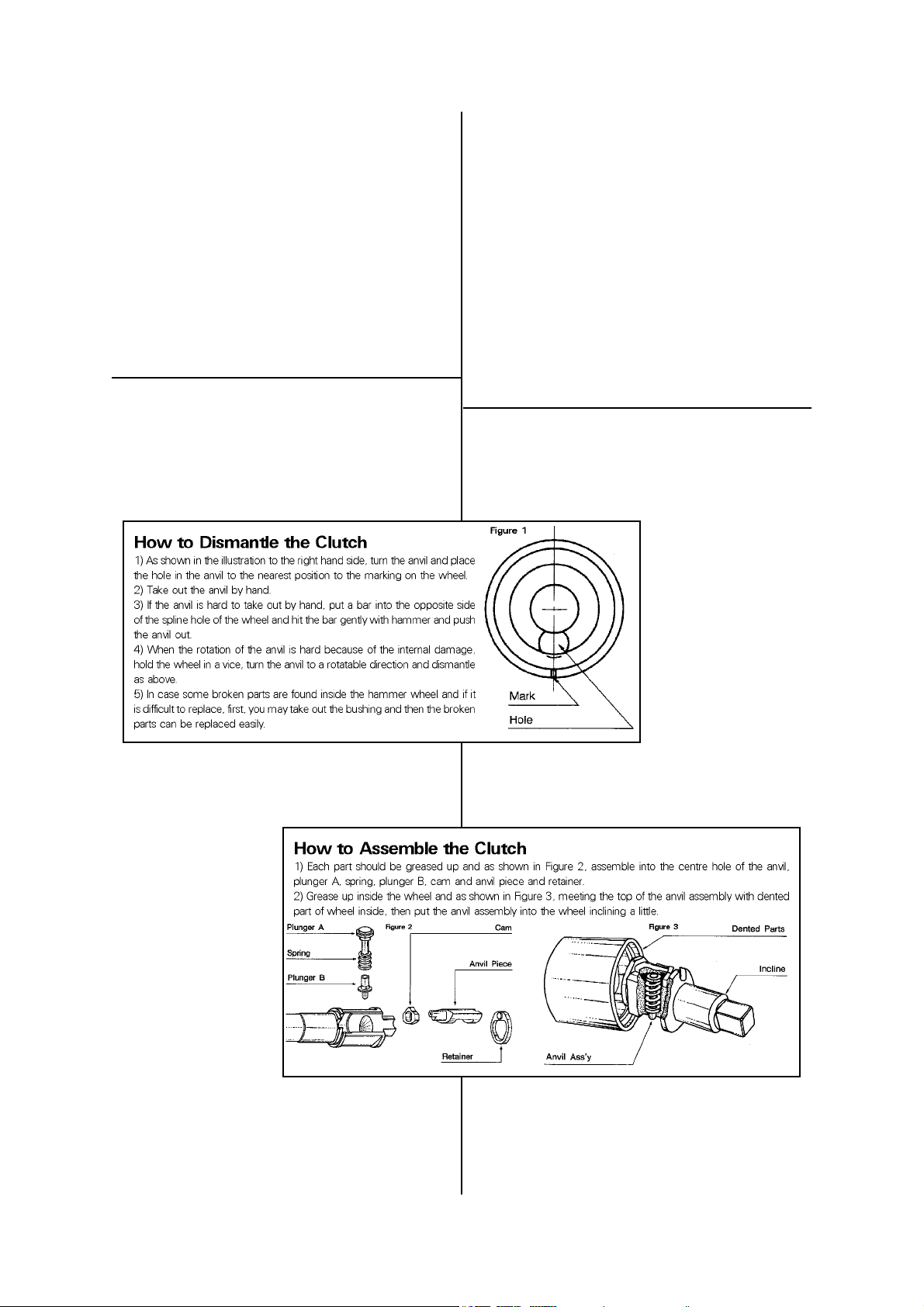
Dismantling & Assembly Instructions
Disconnect tool from air supply.
Clamp handle of impact wrench in a vice with square drive
upwards. Unscrew four cap screw (48). Take out impact housing
C.P. (45). Turn anvil (36) from hammer wheel (34) and place hole
in anvil to nearest position to
the marking on the wheel.
Take out anvil by hand. If anvil
is difficult to take out by hand,
put a bar into opposite side of
spline hole of the wheel and hit
bar softly with a hammer and
push the anvil out. When the
rotation of the anvil is difficult
because of any internal
damage, hold the wheel with a
vice, turn anvil to a rotatable
direction and dismantle as
above. Take out bushing (42),
plunger A (39), plunger B (41),
spring (40), cam (38), anvil
piece (37) and retainer (35)
from anvil. Clamp motor case C.P. (32) of impact wrench.
Unscrew four cap screws (23). Take out handle C.P. (1) and
motor housing gasket (24). Set motor case C.P. on a workbench.
While lightly tapping on end of rotor (28) with a plastic hammer,
take out rotor and rear end plate (26). Take out rear end plate
from rotor.
Reassembly
Always clean every part and coat every part with a thin film of oil
before reassembly. Apply a film of O-ring lubricant to all O-rings
before final assembly. Insert ball bearing (25) to rear end plate
Page No 2
Page 3

UT150 (HP150) 1½" Square Drive Inside Lever Grip Impact Wrench
Ref No Part No Description
1 0142080B Handle C.P.
2 0132117D Throttle Lever
2-1 Z0614x28 Pin
2-2 Z0614x22 Pin
3 0345290 Inlet Bushing
5 Z0665x12A Bolt (4)
6 Z040P16 O-Ring
7 0142013B Throttle Valve Pin
8 Z0115/8D Throttle Valve
9 0132190 Throttle Valve Spring
10 Z040P20 O-Ring
10-1 Z040P28J O-Ring
11 0132150 Plug
12 0442313 Regulator Valve
12-1 Z040P14 O-Ring
13 Z041S25 O-Ring
14 0442350 Regulator Cap
14-1 Z03125 Retainer
14-2 04423501 Regulating Cap Lock
14-3 Z03210 Retainer
15 0442314 Regulating Knob
15-1 Z0563x22 Spring Pin
16 Z0104D Steel Ball
17 0114193 Spring
18 0142015B Reversing Valve
18-1 Z041S18 O-Ring
19 Z03121 Retainer
20 0132915 Reverse Lever
21 Z0674x12 Screw
23 Z0668x22A Bolt (4)
24 0142006B Motor Housing Gasket
25 Z0016205 Ball Bearing
26 0132124 Rear End Plate
26-1 Z0565x10 Pin
27 0140509 Cylinder
27-1 Z0565x10 Pin (2)
Jan 2000 Ver 1.2
Ref No Part No Description
28 0550021 Rotor
29 0550022 Rotor Blade (6)
30 0550023 Front End Plate
31 Z0016206Z Ball Bearing
32 055181B Motor Case C.P. (5000G)
32-1 Z0106D Steel Ball
32-2 0132991 Spring
33 Z041S110 O-Ring
34 0550026 Hammer Wheel
35 0550050 Retainer
36 0550030A Anvil
37 0550028 Anvil Piece
38 0550027 Cam
39 0550051A Plunger A
40 0550053 Spring (5000G)
41 0550052 Plunger B
42 0550029 Bushing
44 0142071 Rubber Protector
45 0550182 Impact Housing C.P.
45-1 0132152 Grease Screw
45-2 Z0996 Toothed Lock Washer
45-3 Z040P6 O-Ring
46 Z0918 Lock Nut (4)
47 Z0968x1 Washer (4)
48 Z0668x45A Bolt (4)
49 0442387 Dead Handle C.P.
51 Z0666x16A Bolt (4)
52 Z040P50 O-Ring
Parts for Inside Handle C.P.
53a 0550180BNS Handle C.P. (NPT)
53b 0550180BTS Handle C.P. (PT)
54 0345417 Throttle Lever
55a 0132919NIS Inlet Bushing (NPT)
55b 0132919IS Inlet Bushing (PT)
57 0550113BT Throttle Lever Pin
Page No 3
Page 4

Declaration of Conformity
Universal Air Tool Company Limited
Unit 8, Lane End Industrial Park, High Wycombe, Bucks, HP14 3BY, England
declare under our sole responsibility that the product
Model UT150 (HP150) 1½” SD Impact Wrench, Serial Number
to which this declaration relates is in conformity with the following standard(s) or other normative document(s)
EN792 (Draft), EN292 Parts 1 & 2, ISO 8662 Parts 1 & 7, Pneurop PN8NTC1
following the provisions of
89/392/EEC as amended by 91/368/EEC & 93/44/EEC Directives
Lane End D.H.Moppett (Man. Director)
Place and date of issue Name and signature or equivalent marking of authorised person
(26). Insert rotor (28) to rear end plate. Insert ball bearing (31) to
front end plate (30). Insert six rotor blades (29) to rotor. Insert
rotor and front end plate to cylinder (27). Insert cylinder to motor
case (32). Put motor housing gasket (24) and handle C.P. (1) on
motor case C.P. Screw four cap screws (23) through handle C.P.
Grip motor case C.P. in leather-covered or copper-covered vice
jaws. Put O-ring on motor case C.P. Put grease on the centre
hole of anvil (36), plunger A (39, plunger B (41), spring (40), cam
(38), anvil piece (37) and retainer (35). Assemble them as Fig. 2.
Grease up inside wheel and as shown in Fig 3, meeting the top
of anvil assembly with dented part of wheel inside, then put anvil
assembly into the wheel inclining a little. Put bushing (42) to
cylinder. Insert cylinder to rod of rotor. Put impact housing C.P.
(45) on motor case C.P. and screw four cap screw (48) through
impact housing C.P.
On completing assembly ensure all parts are tight and trigger and
reverse valve mechanisms operate freely. Depress trigger and
pour into inlet bushing (3) 10ml of a suitable pneumatic tool
lubricating oil. Release trigger and connect to a suitable air supply
and operate the tool slowly for 2 to 3 seconds to allow the oil to
circulate.
Safety Rules When Using an Impact
Wrench
1) Read all the instructions before using this tool. All operators must be
fully trained in its use and aware of these safety rules. All service and
repair must be carried out by trained personnel.
2)The socket used must be of the correct drive size and the "impact"
type. Never use sockets other than impact type.
3) Do not use sockets with excessive wear to the input and output
drives. Check that the square on any other type of drive or the impact
wrench is not cracked or excessively worn before fitting or changing
socket, extension, etc. Make sure that the socket is firmly fixed to the
tool.
4) Always ensure that a stable position or footing is adopted before
using the tool.
5) Ensure that the tool has been correctly set up on a test joint.
Incorrect set up could cause joint breakage with sudden and
unexpected movement of the tool.
6) Use only correct spare parts for repair.
7) Always ensure that the reverse valve is in the correct position
before operating the tool. Do not run the tool unless the socket is first
located on the joint.
8) Check hose and fittings regularly for wear. Use quick connect
couplings only as recommended. See "Putting into Service". Do not
carry the tool by the hose and ensure that the hand is away from the
on/off valve when carrying.
9) Do not attempt to hold or guide the socket by hand when the
tool is running.
10) Do not exceed maximum recommended air pressure.
11) Use safety equipment as recommended.
12) The tool is not electrically insulated. Do not use where there
is a possibility of coming into contact with live electricity.
13) Preferably shut off the air supply before changing sockets or at
least ensure that the hands are well clear of the operating trigger.
14) Take care against entanglement of moving parts of the tool with
clothing, ties, hair, cleaning rags, etc.
15) When loosening fasteners first ensure that there is sufficient
clearance behind the tool to avoid hand entrapment. The tool will
move away from the threaded joint as the nut/bolt etc. is loosened
and rides up the thread moving the tool with it.
16) Only use extensions, adaptors and universal joints suitable for use
with impact wrenches.
17) If the tool appears to malfunction remove from use
immediately and arrange for service and repair.
18) Prolonged exposure to vibration may cause injury.
Accessories
Notes
Distributor
This document may not be copied wholly or in part by anyone without the consent of the Directors of Universal Air Tool Company Limited
Designed & Written in the U.K.
© Copyright of Universal Air Tool Company Limited, established in the United Kingdom, 1994
Page No 4
 Loading...