

Page 1
1701 South Sutro Terrace
Carson City, NV 89704
775.883.2500 Fax 775.883.6388
www.universalanalyzers.com
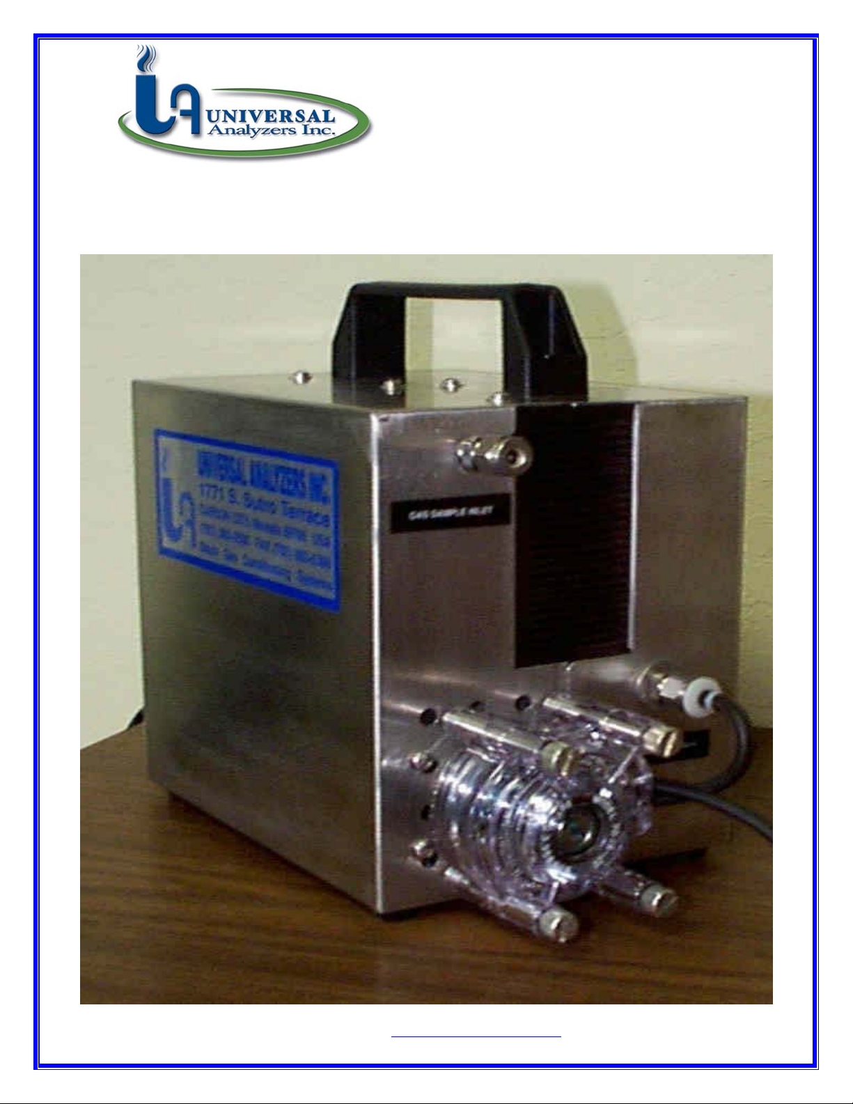
MODEL 510S PORTABLE GAS SAMPLE CHILLER
INSTRUCTION MANUAL
See us on the WEB at http://www.universalanalyzers.com
e-mail address: sales@universalanalysers.com
MAN510 Rev C
Page 2

1701 South Sutro Terrace
Carson City, NV 89704
775.883.2500 Fax 775.883.6388
www.universalanalyzers.com
LIMITED WARRANTY
ALL PRODUCTS MANUFACTURED BY UNIVERSAL ANALYZERS INC. ARE
WARRANTED TO BE FREE OF MANUFACTURING DEFECTS FOR A PERIOD OF ONE
YEAR FROM THE DATE OF RECEIPT AT THE CUSTOMER’S RECEIVING AREA AND
FOR AN ADDITIONAL PERIOD OF UP TO 90 DAYS IF THE PRODUCT IS PLACED IN
SERVICE AFTER BEING IN STORAGE. THIS WARRANTY COVERS MATERIALS AND
LABOR TO RESTORE ANY PRODUCTS TO ORIGINAL FACTORY SPECIFICATIONS IF
A DEFECT IS FOUND WITHIN THE WARRANTY PERIOD.
THE DEFECTIVE PRODUCT SHOULD BE SENT, FREIGHT PREPAID, TO THE
FACTORY IN CARSON CITY, NEVADA. REPAIRS WILL BE PERFORMED AT THE
FACTORY AND RETURNED, PREPAID, BY THE SAME SHIPPING METHOD USED TO
SEND THE PRODUCT TO THE FACTORY.
THIS WARRANTY DOES NOT APPLY WHERE THE EQUIPMENT HAS SUSTAINED
DAMAGE DUE TO NEGLECT, MODIFICATION, CORROSION, OR OTHER REASON
BEYOND THE SCOPE OF THE NORMAL DEFINITION OF “MANUFACTURING
DEFECT”.
FURTHER, THIS WARRANTY IS LIMITED TO REPLACING THE DEFECTIVE
COMPONENTS AND RETURNING THE EQUIPMENT MANUFACTURED BY
UNIVERSAL ANALYZERS INC. TO THE CUSTOMER IN WORKING CONDITION. ANY
OTHER CLAIMS ARE OUTSIDE THE SCOPE OF THIS WARRANTY. NO WARRANTIES
ARE MADE AS TO THE SUITABILITY OF THE USE OF THE EQUIPMENT IN ANY
PARTICULAR APPLICATION OR LOCATION. THE SUITABILITY OF THE USE OF THE
EQUIPMENT IS THE RESPONSIBILITY OF THE CUSTOMER AND THE INSTALLING
CONTRACTOR.
Page 3

1701 SOUTH SUTRO TERRACE
CARSON CITY, NV 89706-0364
TELEPHONE (800) 993-9309
FAX: 775-883-6388
(775) 883-2500
UNIVERSAL ANALYZERS MODEL 510S SAMPLE COOLER
SPECIFICATIONS
SAMPLE FLOW RATE: 0 to 2 L/M (at STP)
MAXIMUM INLET TEMPERATURE: 500o F. (260o C.)
MAXIMUM INLET GAS DEW POINT: 180o F. (82o C.)
MAXIMUM INLET WATER CONCENTRATION: 50%*
MINIMUM AMBIENT TEMPERATURE: 32o F. (0o C.)
MAXIMUM AMBIENT TEMPERATURE: 105o F. (41o C.)*
MAXIMUM COOLING POWER: 50 BTU'S/Hr. (47 kJ/Hr.)
OUTLET SAMPLE DEW POINT: 41o F. (5o C.), adjustable
MAXIMUM INPUT POWER: 150 WATTS
VOLTAGE: 90 - 125 VAC, 50/60 Hz
or
180 - 250 VAC, 50/60 Hz
ELECTRICAL CLASSIFICATION: NEMA 1
DIMENSIONS: 9" x 10" x 6", HWD
WEIGHT: 11 LB's., (5 KG)
*at reduced flow rates. See capacity chart.
See us on the WEB at http://www.universalanalyzers.com
e-mail address: sales@universalanalyzers.com
510 Text Rev -
Page 4

MODEL 510S SAMPLE COOLER
OPERATING INSTRUCTIONS
APPLICATION
The Model 510S was designed as a self contained transportable sample conditioning system to
dehydrate a gas sample prior to being analyzed by a combustion monitor or transportable infrared analyzer. It can be left in place, powered continuously to protect an analyzer which is on
stream, continuously analyzing a gas sample.
DESCRIPTION
The Model 510S sample cooler is a thermoelectric chiller containing a DC power supply, a
temperature controller, a 316SS heat exchanger, and a condensate pump all encased within a
stainless steel enclosure. The enclosure has a convenient handle to make it easily transportable.
A power cord is provided to connect the chiller to line power.
The heat exchanger is milled out of a solid block of 316SS with tubing fittings welded onto the
block. The sample path is in the shape of a “V” with the inlet and outlet at the top of the block
and the condensate drain at the bottom of the “V”. Two thermoelectric elements are sandwiched
between the heat exchanger and the heat sink which discharges the heat produced by the
thermoelectric elements
Two thermoelectric elements are wired in series and supplied with 24 VDC to cool the sample
heat exchanger. A controller is provided to interrupt the current through the thermoelectric
elements when the temperature drops below the temperature set point. The temperature is
factory set at 5o C. This temperature can be adjusted using a potentiometer on the control circuit
board. The temperature sensor is an AD592 semiconductor device.
The heat which is removed from the gas sample (and that which is created by the Thermoelectric
Elements) is discharged by a heat sink which is cooled with a 24 VDC muffin fan blowing
directly into the heat sink. The heat sink is fabricated from solid block of aluminum which
eliminates the epoxy joints in more conventional heat sink designs which are barriers to heat
conduction. The result is a heat removal system with superior performance under all conditions.
A small peristaltic pump flowing at a continuous rate of 5 ml per minute is used to remove the
condensate from the heat exchanger.
Page 5

PERFORMANCE:
MAXIMUM FLOW RATE: 3 LPM
WATER VAPOR CONCENTRATION
AMBIENT IN GAS SAMPLE (BY VOLUME) .
TEMPERATURE 15%_ 30%_ 50%__
77O F. (25O C.) 2 LPM 1 LPM 0.5 LPM (EXIT DEW POINT: 7O C.)
O
F. (32O C.) 2 LPM 1 LPM 0.5 LPM (EXIT DEW POINT: 9O C.)
90
O
105
F. (41O C.) 2 LPM 1 LPM 0.5 LPM (EXIT DEW POINT: 18O C.)
TROUBLE SHOOTING
The presence of water in liquid form after the sample cooler is an indication of a fault in the
system. Reasons for the presence of condensate in the system after the sample cooler could be
one or more of the following:
1. Overloading of the cooling capacity of the chiller due to too much
water vapor in the sample or due to too great a sample flow rate.
2. The condensate pump may be faulty. The heat exchanger may be full
of condensate. This could be due to the need to change the peristaltic pump
tubing. The tubing has a 3 to 6 month life.
3. An air leak may be in the condensate removal system allowing air to
enter and blow the condensate back into the heat exchanger.
4. The temperature of the air passing through the cooler to cool the heat
sink is too high. This could be due to placement of the cooler near a heat source.
5. The sample cooler could have failed.
If additional information is required, telephone assistance can be obtained from the factory by
calling (800) 993-9309 or (775) 883-2500 or FAX request to (775) 883-6388.
Page 6

12345678
D
C
HEATSINK FAN
(COOL AIR INTAKE)
REAR VIEW
REMOVABLE COVER SCREWS
(5 TYP)
120VAC INPUT POWER
(POWER CORD INCLUDED)
SAMPLE OUTLET
1/4" TUBE
LEFT SIDE
6 3/8"
11 3/8"
9 1/8"
A
AD592 HOUSING
INSULATED
HEAT EXCHANGER
CONTROL
CIRCUIT
BOARD
SAMPLE INLET
1/4" TUBE
D
C
SECTION A-A
A
POWER SUPPLY BOARD
PERISTALTIC DRAIN PUMP HEAD
CONDENSATE DRAIN
RIGHT SIDE
B
A
REMOVABLE COVER
CONDENSATE DRAIN OUTLET FITTING
TO PERISTALTIC DRAIN PUMP HEAD
(MUST DISCONNECT TUBE FROM
FITTING TO REMOVE COVER)
1). SEE SHEET 2 FOR WIRING SCHEMATIC
D 07 /15/03 Moved DIN Drwg to P0738, Added Wiring Sht2 RPH JK
REVISIONS
MODEL 510 PORTABLE SAMPLE
COOLER OUTLINE
FORPART NO.
NOT ISSUED
INSTRUMENT
UNIVERSAL ANALYZERS INC.
1701 South Sutro Terrace
Carson City, Nevada 89706 USA
DRAWN BY
APVD BY
EV MUSSELMAN
TED BARBEN II
DATE SCALE SIZE SHEET
08/10/95
1 : 1
DRAWING NO
P0140
E
1 OF 2
12345678
B
APVDDWNDESCRIPTIONDATEREV
A
Page 7

8
NDUIT AND WIRING NOTES
CO
ELECTRICAL AREA CLASSIFICATION:
1.
SYSTEM IS CONFIGURED AT THE FACTORY FOR REQUIRED VOLTAGE.
CONTACT FACTORY FOR VOLTAGE CHANGE REQUIREMENTS
AC WIRING SHALL BE INDIVIDUAL CONDUCTORS OF STRANDED TINNED COPPER WITH
2.
300V, TYPE TFE INSULATION. MINIMUM WIRE SIZE SHALL BE 18 AWG
D
BLACK
RED
COLOR CODE SHALL BE AS FOLLOWS:
3.
DC CONTROL WIRING SHALL BE INDIVIDUAL CONDUCTORS OF STRANDED TINNED COPPER
WITH 300V, TYPE TFE INSULATION. MINIMUM WIRE SIZE SHALL BE 18 AWG.
COLOR CODE SHALL BE AS FOLLOWS: RED
INSIDE - GENERAL PURPOSE
120VAC
HOT - BLACK
NEUTRAL
- WHITE
GROUND
- GREEN
+
BLUE
-
1234567
D
HEAT EXCHANGER
24VDC FAN
AD592
T.C. CONNECTOR
C
PELTIERS
RED
BLK
RED
BLK
H
N
G
MOLEX
CONNECTORS
GRN/YEL
B
GRN
POWER
ENTRY
RECEPTACLE
120VAC
BLU
BLU
BRN
BRN
PERISTALTIC PUMP
120VAC
BRN
L
BLU
GRN/YEL
FUSE
N
POWER SUPPLY CIRCUIT BOARD
GRN
A
8
510
BANG BANG
CONTROLLER
CARD
RTN
+16.5V
BLACK -
3
2
1
RED +
TRIM
BLK
RED
RED -
SHIELD
BLK +
GRN
BLK
BLK
RED
RED
TURN CLOCKWISE
= COOLER
SET @ 4.0°-4.5°C
D 07/15/03 Was DIN Layout Drwg, Moved to P0738 RPH JK
DATE
REV
DIMENSIONS
IN INCHES
TOLERANCES
.0 ± .015"
.00 ± .010"
.000 ± .005"
FRACTIONAL
ALL ± .015"
ANGLES ± 1° 30'
UNLESS
OTHERWISE
SPECIFIED
MATERIAL/DESCRIPTION
MODEL 510
WIRING SCHEMATIC
PART NO.
Not Issued
UNIVERSAL ANALYZERS INC.
1701 South Sutro Terrace
Carson City, Nevada 89706 USA
DRAWN BY
EV MUSSELMAN
APVD BY
TED BARBEN II
DATE SCALE SIZE SHEET
08/10/95 2 OF 2
REVISIONS
INSTRUMENT
DRAWING NO
P0140
NTS
C
B
APVD
DWNDESCRIPTION
PART NO.
A
FOR
D
1234567
Page 8

1701 SOUTH SUTRO TERRACE
CARSON CITY, NV 89706-0364
TELEPHONE (800) 993-9309
FAX: 775-883-6388
(775) 883-2500
SPARE PARTS FOR MODEL 510 TRANSPORTABLE SAMPLE COOLER
Part Number
Description Price each
9216-0017 2’ length of 1/4” O. D. Viton sample tubing, #16 $ 14.50
3016-0003 Thermoelectric elements $ 192.00
9515-0034 Insulation kit $ 63.00
5200-0062 316SS Heat Exchanger $ 108.00
4800-0013 24 VDC Cooling Fan $ 74.00
1150-0017 Temperature Transducer Assembly $ 75.00
3600-0018 Control Circuit Board $ 130.00
5400-0006 24 VDC Power Supply $ 210.00
4958-0028 Peristaltic Condensate Pump Motor, 115 VAC $ 210.00
4958-0031 Peristaltic Condensate Pump Motor, 230 VAC $ 210.00
4958-0055 Peristaltic Condensate Pump Head, #16 $ 130.00
See us on the WEB at http://www.universalanalyzers.com
e-mail address: sales@universalanalyzers.com
510 Spare Parts Rev -
Page 9

Page 10

Page 11

Page 12

Page 13

Page 14

Page 15

 Loading...