

Unity Opto Technology MVL-564BG Datasheet
T-1 3/4 (
φφ
5mm)
InGaN LED LAMPs
MVL-564BG
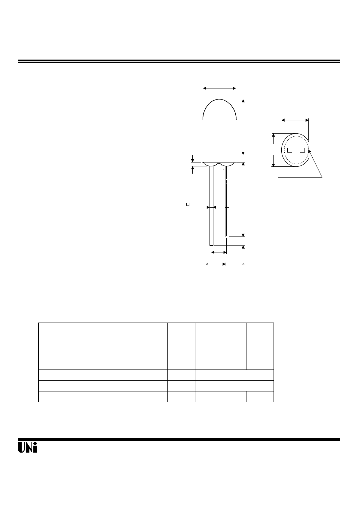
Description Package Dimensions
pf
af
R
opr
stg
ot
(.300)
(.217)
FLAT DENOTES
The MVL-564BG, a blue source color device, is made with
InGaN ( on SiC substrate) LED die.
The package is T-1 3/4 (φ5mm) water clear plastic
φ5.00
(.200)
Unit: mm ( inches )
lens package.
Applications
l Full color displays & moving message signs
l Solid state incandescent replacement bulbs
l High ambient panel indicators
l Color printers & scanners
l Medical & Analytical instruments
Features
l High performance - 2.5mW (490nm)
l Superior SiC substrate technology
l Excellent chip to chip consistency
l High reliability
l Stopper
7.70
5.90
1.00
SEE NOTE 2
0.50 TYP.
(.020)
2.54
(.100)
A
Notes :
1. Tolerance is ±0.25 mm (.010") unless otherwise noted.
2. Protruded resin under flange is 0.8 mm (.031") max.
3. Lead spacing is measured where the leads emerge from the package.
(.040)
25.40 MIN
(1.000)
1.00MIN.
(.040)
C
(.230)
5.50
Absolute Maximum Ratings
Parameter Symbol Maximum Rating Unit
Peak Forward Current(1/10 Duty Cycle@1KHz ) I
Continuous Forward Current I
Reverse Voltage V
Operating Temperature Range T
Storage Temperature Range T
Electrostatic Discharge Threshold E
Unity Opto Technology Co., Ltd.
@ T
A
100 mA
30 mA
5 V
o
-20
Cto +80oC
o
-30
C to +100oC
1000 V
=25
o
C
09/11/2000
MVL-564BG
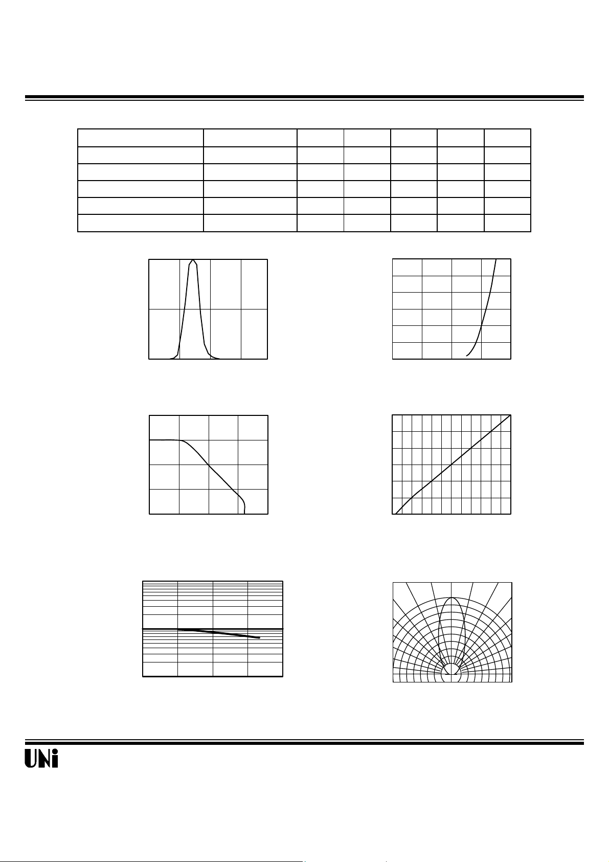
Optical-Electrical Characteristics
AMBIENT TEMPERATURE
FIG.4 RELATIVE LUMINOUS INTENSITY
VS. FORWARD CURRENT
0o 10o 20
Parameter Test Conditions Symbol Min . Typ . Max . Unit .
Luminous Intensity
Forward Voltage
Reverse Current
Dominant Wavelength
Viewing Angle
IF=20mA I
IF=20mA V
VR=5V
IF=20mA
IF=20mA
Typical Optical-Electrical Characteristic Curves
1
0.5
0
Relative Luminous Intensity
380 450 520 590 660
Wavelength (nm)
FIG.1 RELATIVE INTENSITY LUMINOUS
VS. WAVELENGTH
40
(mA)
30
F
20
10
Forward Current I
0
0 25 50 75 100
Ambient Temperature (
FIG.3 FORWARD CURRENT VS.
AMBIENT TEMPERATURE
10
o
C)
2θ
A
=25
µA
o
C
@ T
V
F
I
R
λ
d
1/2
400 900 - mcd
- 3.5 4.0 V
- - 10
- 490 - nm
- 30 - deg.
30
25
(mA)
F
20
15
10
5
Forward Current I
0
0 1 2 3 4
Forward Voltage (V)
FIG.2 FORWARD CURRENT VS.
FORWARD VOLTAGE
1.50
1.25
=20mA
1.00
F
0.75
0.50
0.25
Normalized at I
Relative Luminous Intensity
0.00
0 5 10 15 20 25 30
Forward Current IF (mA)
o
o
30
1
0.1
Relative Luminous Intensity
0 25 50 75
Ambient Temperature (
FIG.5 LUMINOUS INTENSITY VS.
Unity Opto Technology Co., Ltd.
o
40
o
1.0
0.9
0.8
Relative Luminous Intensity
50
60
70
80
90
o
o
o
o
0.5 0.3 0.1 0.2 0.4 0.6
o
C)
FIG.6 RADIATION DIAGRAM
09/11/2000
 Loading...