

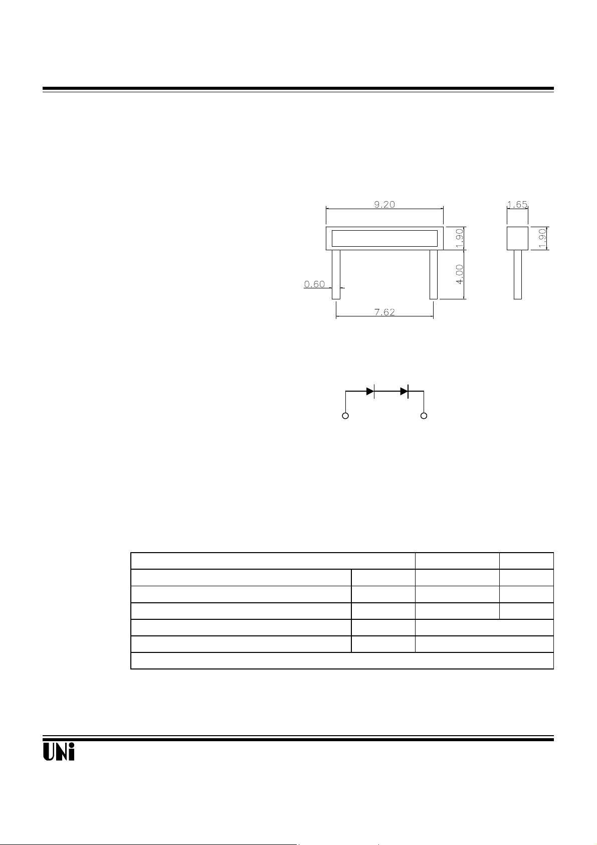
SIDE LOOK PACKAGE
SOLID STATE LAMP
MSL-854UYL
Description Package Dimensions
ad
af
R
opr
stg
The MSL-854UYL is designed based on an industry
standard package for ease of handing and use. Units : mm
The package is water clear epoxy within white plastic.
Applications
l LCD backlighting
l Symbol backlighting
l Front panel indicator
Features
l High performance
l Excellent chip to chip consistency
l High reliability
Absolute Maximum Ratings
Power Dissipation P
Continuous Forward Current I
Reverse Current(VR=5V) I
Operating Temperature Range T
Storage Temperature Range T
Lead Soldering Temperature 260oC for 5 second (2.0mm From Body)
ANODE CATHODE
Notes :
1. All dimensions are in millimeters.
2. Tolerance is ± 0.25 mm unless otherwise noted.
'@ TA=25oC
Parameter Symbol Maximum Rating Unit
200 mW
35 mA
10
-40oC to +85oC
-40oC to +85oC
µA
Unity Opto Technology Co., Ltd.
11/06/2000

MSL-854UYL
Optical-Electrical Characteristics
Relative Luminous Intensity
FIG.4 RELATIVE LUMINOUS INTENSITY
0o 10o 20
FIG.2 FORWARD CURRENT VS.
λ
500
600
70
Spectral
Halfwidth
∆l(nm)
PART NO
MSL-854UYL
Color
Dominant
Wave
Langth
Emitted Lens TYP MAX MIN TYP
D
Amber Water Clear
590 15 4.1 4.7 300 500
Typical Optical-Electrical Characteristic Curves
1
0.
0
Relative Luminous Intensity
Wavelength (nm)
FIG.1 RELATIVE LUMIINOUS INTENSITY VS. WAVELENGTH
Forward Luminous
Voltage Intensity
@IF=20mA @IF=20mA
(V) (mcd)
@ TA=25oC
Viewing Angle
2θ
1/2
(deg)
110
35
30
25
20
15
10
5
Forward Current (mA)
0
0.0 2.0 4.0 6.0
Forward Voltage (V)
FORWARD VOLTAGE
1
0.8
0.6
=35mA
F
0.4
0.2
0
Normalized at I
Relative Luminous Intensity
0 5 10 15 20 25 30 35
Forward Current (mA)
VS. FORWARD CURRENT
40
35
(mA)
Forward Current I
30
F
25
20
15
10
5
0
0 10 20 30 40 50 60 70 80 90 100
Ambient Temperature T
(oC)
A
FIG.3 FORWARD CURRENT
VS. AMBIENT TEMPERATURE
o
1.0
0.9
0.8
0.5 0.3 0.1 0.2 0.4 0.6
30
40
50
60
70
80
90
o
o
o
o
o
o
o
FIG.5 RADIATION PATTERN DIAGRAM
Unity Opto Technology Co., Ltd.
11/06/2000
 Loading...