

Surface Mount Chip LEDs
MSL-194UG
Description
The MSL-194UG, a YELLOW GREEN source
Chip LED device, is designed in an indnstry
standard package suitable for SMT assembly
method. It utilizes AlGaInP on GaAs LED chip
technology and water clear epoxy package.
Applications
l Small Size
l Industry Standard Footprint(0603)
l Compatible with IR Solder process
l Availalble in 8 mm Tape on 7"(178mm)
Diameteer Reels
Features
l Push-Button Backlighting
l LCD Backlighting
l Symbol Backlighting
l Front Panel Indicator
Absolute Maximum Ratings
Parameter Symbol Maximum Rating Unit
Peak Forward Current(1/10 Duty Cycle@1KHz ) I
FP
100 mA
DC Forward Current I
F
25 mA
Power Dissipation P
D
68 mW
Reverse Voltage V
R
5 V
Operating Temperature Range T
OPR
-20
o
C to +80oC
Storage Temperature Range T
STG
-30
o
C to +100oC
11/24/2000
Unity Opto Technology Co., Ltd.
@ T
A
=25
o
C
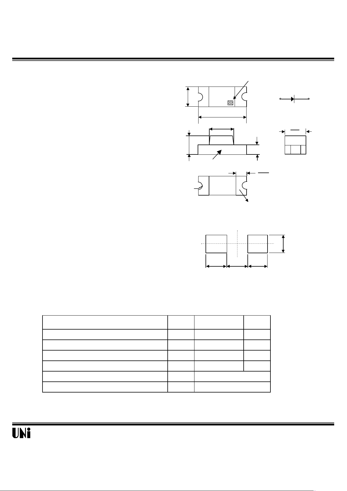
NOTE:
1. All dimensions are in millimeter (inches)
2. Tolerance is ± 0.1mm (.004") unless otherwise specified.
POLARITY
Recommended Solder Patterns
Package Dimensions
0.80
(0.032)
0.80
(0.032)
0.72
(0.028)
0.80
(0.032)
CATHODE MARK
0.30
( 0.012 )
1.20
(0.047)
0.8
(0.032)
1.60
( 0.063 )
0.80
(.032)
0.20
(0.008)
SOLDERING
TERMINAL
0.80
( 0.032 )
PCB
R.0.175
(0.007)
MSL-194UG
Optical-Electrical Characteristics
Parameter Test Conditions Symbol Min . Typ . Max . Unit .
Luminous Intensity
IF=20mA I
V
30 80 - mcd
Forward Voltage
IF=20mA V
F
- 2.2 2.5 V
Reverse Current
I
R
- - 10
µA
Peak/Dominant Wavelength
IF=20mA
λp/λ
d
- 575/574 - nm
Spectral Linewidth IF=20mA
∆λ
- 20 - nm
Viewing Angle
IF=20mA
2θ
1/2
- 130 - deg.
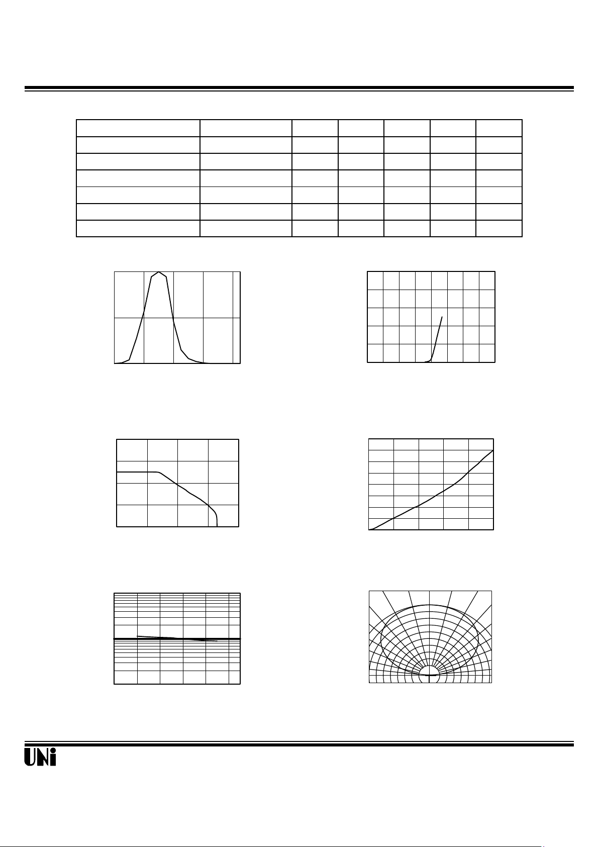
Typical Optical-Electrical Characteristic Curves
11/24/2000
VR=5V
@ T
A
=25
o
C
Unity Opto Technology Co., Ltd.
Ambient Temperature (
o
C)
FIG.5 LUMINOUS INTENSITY VS.
AMBIENT TEMPERATURE
0
10
20
30
40
0 25 50 75 100
Ambient Temperature( )
FIG. 3 FORWARD CURRENT
VS. AMBIENT TEMPERATURE.
Forward Voltage (V)
FIG.2 FORWARD CURRENT
VS. FORWARD VOLTAGE.
Forward Current I
F
(mA)
Relative Luminous Intensity
( Normalized at I
F
=20 mA )
Forward current (mA)
FIG. 4 RELATIVE LUMINOUS INTENSITY
VS. FORWARD CURRENT.
0.5 0.3 0.1 0.2 0.4 0.6
Relative Luminous Intensity
1.0
0.9
0.8
0o 10o 20
o
FIG.6 RADIATION DIAGRAM
90°
70°
30°
40°
50°
80°
Relative Luminous Intensity
Relative Luminous Intensity
Forward Current I
F
(mA)
0
10
20
30
40
50
0 1 2 3 4
0
0.2
0.4
0.6
0.8
1
1.2
1.4
1.6
0 5 10 15 20 25
0.1
1
10
0 20 30 50 70 90
0
0.5
1
520 560 590 630 670
Wavelength (nm)
FIG.1 RELATIVE INTENSITY LUMINOUS
VS. WAVELENGTH
 Loading...