

Surface Mount Full Color Chip LEDs
MSL-157RGB
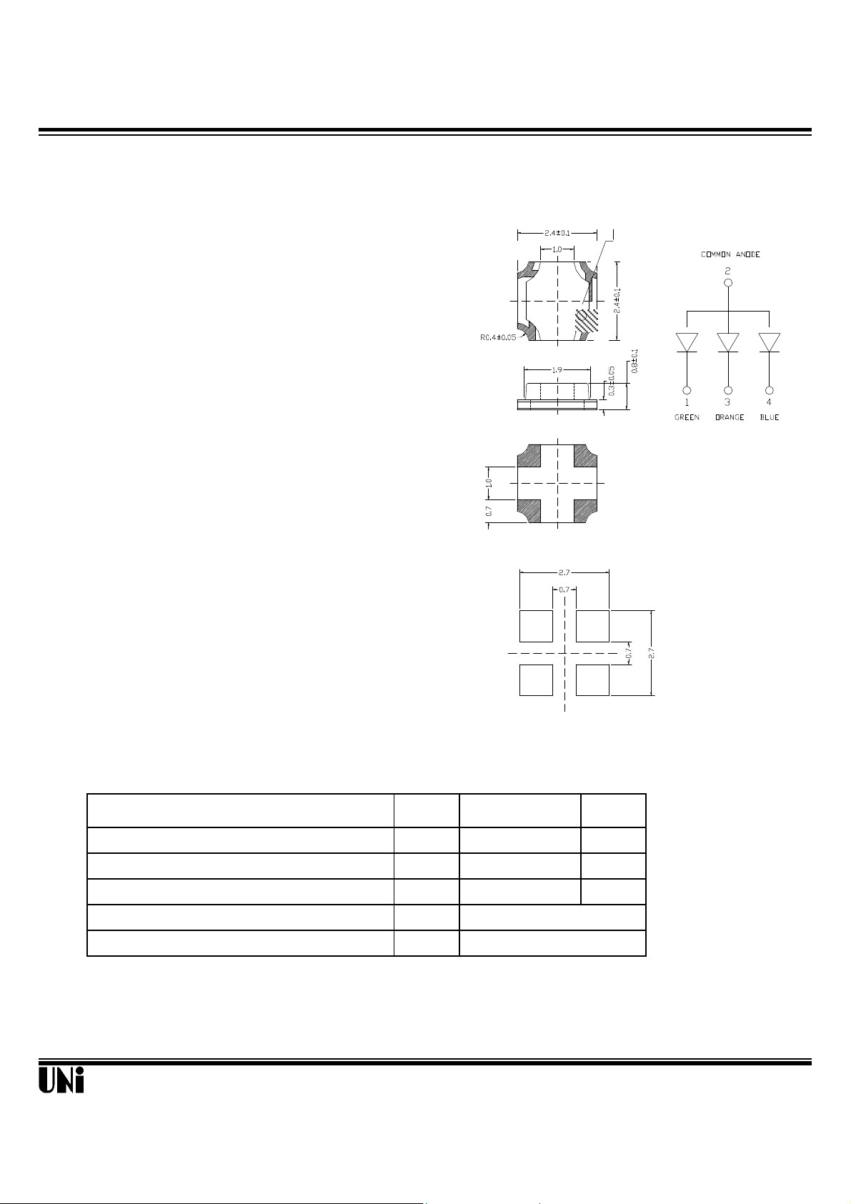
Description Package Dimensions
2
3
1
The MSL-157RGB , a full colors device, is made with
InGaN ( on Sapphire substrate) BLUE, TRUE GREEN and AlInGaP
SOFT RED LED dice. It is PCB type package, suitable for all
SMT assembly methods.
Features
l Key pad backlighting
l Symbol backlighting
l Front panel indicator
Unit: mm
Common Anode
4
Absolute Maximum Ratings
Parameter Symbol Maximum Rating Unit
Peak Forward Current(1/10 Duty Cycle@1KHz )
Continuous Forward Current
Reverse Voltage
Operating Temperature Range
Storage Temperature Range
Unity Opto Technology Co., Ltd.
Notes :
1. All dimensions are in millimeters.
2. Tolerance is ± 0.10 mm unless otherwise noted.
@ T
I
FP
I
F
V
R
T
opr
T
stg
100 mA
30 mA
5 V
o
-20
C to +80oC
o
-30
C to +100oC
=25
A
o
C
08/07/2001
MSL-157RGB
Optical-Electrical Characteristics
Blue
Green
Orange
@
BGR
Parameter Test Conditions Symbol Min . Typ . Max . Unit .
Luminous Intensity
Forward Voltage
Reverse Current
Peak/Dominant Wavelength
Spectral Linewidth IF=20mA
Viewing Angle
IF=20mA I
IF=20mA V
IF=20mA
IF=20mA
VR=5V
∆λ
2θ
o
TA=25
V
F
I
R
λ
d
15 40 - mcd
- 3.7 4.2 V
- - 100
- 470 - nm
C
µA
- 26 - nm
1/2
- 120 - deg.
Parameter Test Conditions Symbol Min . Typ . Max . Unit .
Luminous Intensity
Forward Voltage
Reverse Current
Peak/Dominant Wavelength
Spectral Linewidth IF=20mA
Viewing Angle
IF=20mA I
IF=20mA V
VR=5V
IF=20mA
λ
∆λ
IF=20mA
2θ
V
I
R
Parameter Test Conditions Symbol Min . Typ . Max . Unit .
Luminous Intensity
Forward Voltage
Reverse Current
Peak/Dominant Wavelength
Spectral Linewidth IF=20mA
Viewing Angle
IF=20mA I
IF=20mA V
VR=5V
IF=20mA
λ
∆λ
IF=20mA
2θ
V
I
R
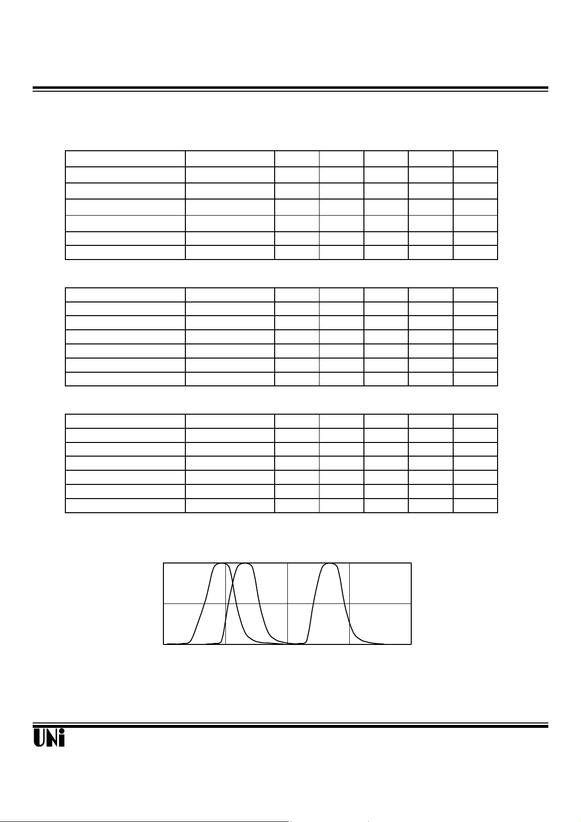
Typical Optical-Electrical Characteristic Curves
=25
A
o
C
@ T
70 150 - mcd
F
d
- 3.7 4.2 V
- - 100
- 525 - nm
µA
- 35 - nm
1/2
- 120 - deg.
@ T
=25
A
o
C
25 50 - mcd
F
d
- 2.0 2.6 V
- - 100
- 625 - nm
µA
- 20 - nm
1/2
- 120 - deg.
1
0.5
0
Relative Luminous Intensity
Unity Opto Technology Co., Ltd.
400 480 550 630
Wavelength (nm)
FIG.1 RELATIVE INTENSITY LUMINOUS
VS. WAVELENGTH
08/07/2001

MSL-157RGB
Typical Optical-Electrical Characteristic Curves
0o 10o 20
80°
B/G
R
35
R
30
(mA)
F
25
20
15
10
5
Forward Current I
0
0.0 2.0 4.0 6.0
Forward Voltage (V)
FIG.2 FORWARD CURRENT VS.
FORWARD VOLTAGE
B.G
40
(mA)
30
F
20
10
Forward Current I
0
0 25 50 75 100
Ambient Temperature (
FIG.3 FORWARD CURRENT VS.
AMBIENT TEMPERATURE
o
C)
1.6
1.4
1.2
=20mA
F
1
0.8
0.6
0.4
0.2
Normalized at I
Relative Luminous Intensity
0
0 5 10 15 20 25
Forward Current IF (mA)
FIG.4 RELATIVE LUMINOUS INTENSITY
VS. FORWARD CURRENT
10
1
0.1
Relative Luminous Intensity
0 20 30 50 70 90
Ambient Temperature (
o
C)
FIG.5-3 RELATIVE LUMINOUS INTENSITY VS.
AMBIENT TEMPERATURE
10
1
0.1
Relative Luminous Intensity
0 25 50 75
Ambient Temperature (
o
C)
FIG.5-2 RELATIVE LUMINOUS INTENSITY VS.
AMBIENT TEMPERATURE
o
30°
40°
1.0
0.9
0.8
Relative Luminous Intensity
0.5 0.3 0.1 0.2 0.4 0.6
50°
70°
90°
FIG.6 RADIATION DIAGRAM
Unity Opto Technology Co., Ltd.
08/07/2001
 Loading...