

AlGaAs/GaAs
HIGH POWER
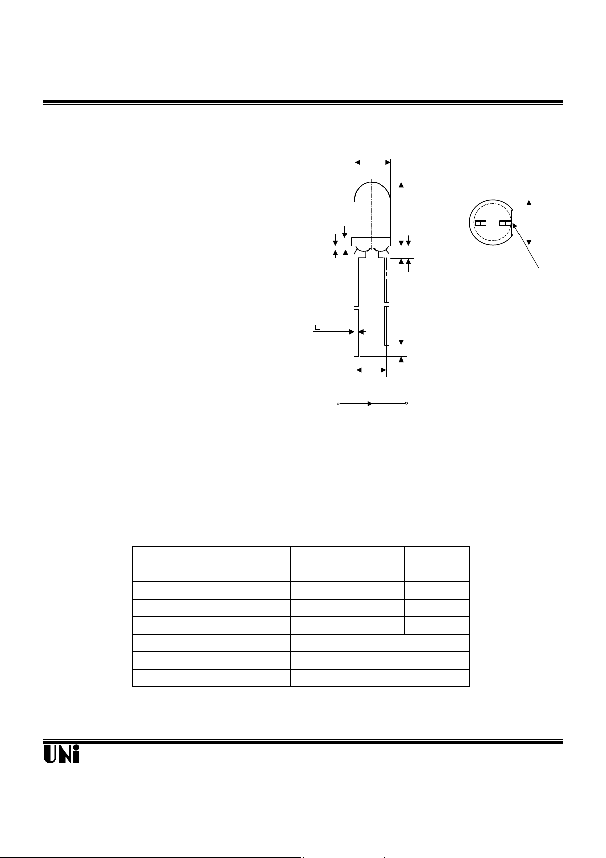
T-1 PACKAGE
INFRARED EMITTING DIODE
MIE-304A2
(.020)
FLAT DENOTES CATHODE
(.207)
A
C
SEE NOTE 3
Description Package Dimensions
The MIE-304A2 is a high power infrared eimtting
diode in GaAs technology with AlGaAs window
3.00
Unit: mm (inches)
coating molded in water clear plastic package.
1.00
(.039)
5.25
0.80±0.50
(.032±.020)
23.40MIN.
Features
l High radiant power and high radiant intensity
l Suitable for DC and high pulse current operation
l Standard T-1 ( φ 3mm) package, radiation angle: 25°
l Peak wavelength λp = 940 nm
l Good spectral matching to Si-Photodetector
0.50 TYP.
2.54 NOM.
(.100)
Notes :
1. Tolerance is ± 0.25 mm (.010") unless otherwise noted.
2. Protruded resin under flange is 0.8 mm (.031") max.
3. Lead spacing is measured where the leads emerge from the package.
(.921)
1.00 MIN.
(.040)
4.00
(.158)
Absolute Maximum Ratings
Parameter Maximum Rating Unit
Power Dissipation 120 mW
Peak Forward Current 1 A
Continuous Forward Current 100 mA
Reverse Voltage 5 V
Operating Temperature Range
Storage Temperature Range
Lead Soldering Temperature
Unity Opto Technology Co., Ltd.
@ TA=25oC
-55oC to +100oC
-55oC to +100oC
260oC for 5 seconds
02/04/2002
MIE-304A2
Optical-Electrical Characteristics
Parameter Test Conditions Symbol Min. Typ . Max. Unit
Radiant Intensity
Forward Voltage
Reverse Current
Peak Wavelength
Spectral Bandwidth
View Angle
IF=20mA
IF=50mA V
VR=5V I
IF=20mA
IF=20mA
IF=20mA 2θ
Ie 1.3 2.5 - mW/sr
F
R
λ
∆λ
1/2
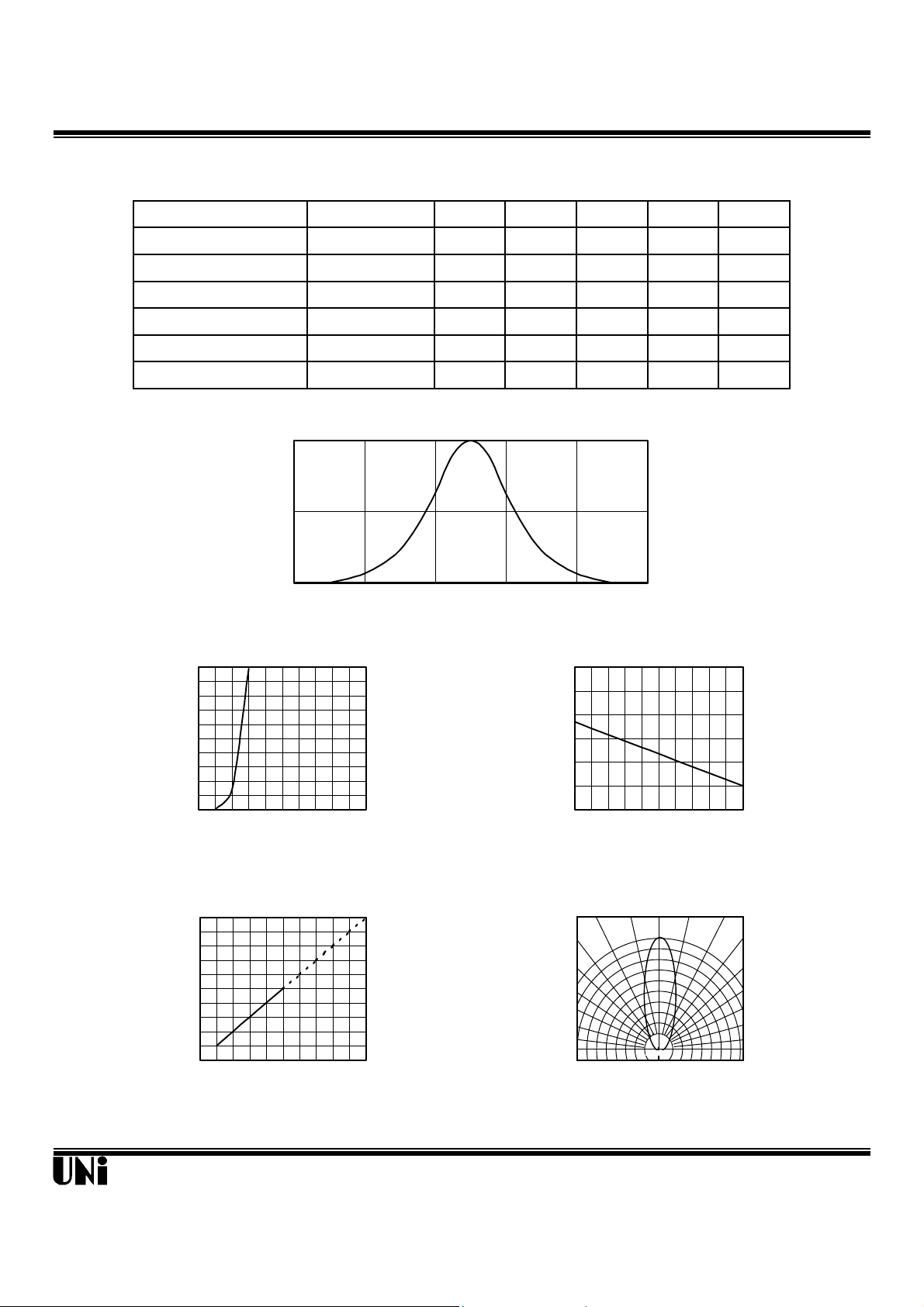
Typical Optical-Electrical Characteristic Curves
1
0.5
Relative Radiant Intensity
0
840 880 920 960 1000 1040
Wavelength (nm)
FIG.1 SPECTRAL DISTRIBUTION
@ TA=25oC
- 1.30 1.50 V
- - 100
µA
- 940 - nm
- 50 - nm
- 25 - deg .
100
80
60
40
20
Forward Current (mA)
0
0.8 1.2 1.6 2.0 2.4 2.8
Forward Voltage (V)
FIG.2 FORWARD CURRENT VS.
FORWARD VOLTAGE
5
4
3
2
1
0
Relative Radiant Intensity
0 20 40 60 80 100
Forward Current (mA)
FIG.4 RELATIVE RADIANT INTENSITY
VS. FORWARD CURRENT
3.0
2.5
2.0
1.5
1.0
0.5
0.0
Relative Radiant Intensity
-40 -20 0 20 40 60
Ambient Temperature TA(oC)
FIG.3 RELATIVE RADIANT INTENSITY
VS. AMBIENT TEMPERATURE
0° 10° 20°
1.0
0.9
0.8
Relative Radiant Intensity
0.5 0.3 0.1 0.2 0.4 0.6
FIG.5 RADIATION DIAGRAM
30°
40°
50°
60°
70°
80°
90°
Unity Opto Technology Co., Ltd.
02/04/2002
 Loading...