

GaAlAs 1.8mm PACKAGE
INFRARED EMITTING DIODE
MIE-184H4
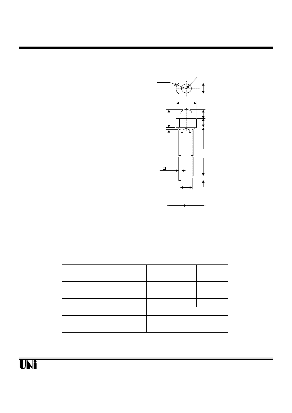
Description Package Dimensions
s pulse)
(.020)
(.055)
(.063)
(.094)
The MIE-184H4K is a GaAlAs infrared LED having a
peak wavelength at 850nm. It features ultra-high power,
high response speed and molded package with higher
R 1.70
(.067)
φ1.80
Unit : mm (inches )
2.40
radiant intensity. In addition to improving the S/N ratio
in applied optical systems, the MIE-184H4K has greatly
improved long-distance characteristics as well as significantly increased its range of applicability .
3.00
3.30
1.40
1.60
Features
l Ultra-High radiant intensity
l High response speed
l Special 1.8mm package, radiant angle : 35
l Peak wavelength λ
=850 nm
P
o
0.50 TYP.
2.54 NOM.
25.40MIN.
(1.000)
1.00MIN.
(.040)
SEE NOTE 3
(.100)
C A
Application
l Data communication
l SIR
Notes :
1. Tolerance is ± 0.25 mm (.010") unless otherwise noted.
2. Protruded resin under flange is 0.4 mm (.015") max.
3. Lead spacing is measured where the leads emerge from the package.
Absolute Maximum Ratings
Power Dissipation 100 mW
Peak Forward Current(300pps,10µ
Continuous Forward Current 100 mA
Reverse Voltage 5 V
Operating Temperature Range
Storage Temperature Range
Lead Soldering Temperature
Unity Opto Technology Co., Ltd.
@ TA=25oC
Parameter Maximum Rating Unit
1 A
-55oC to +100oC
-55oC to +100oC
260oC for 5 seconds
02/04/2002
MIE-184H4K
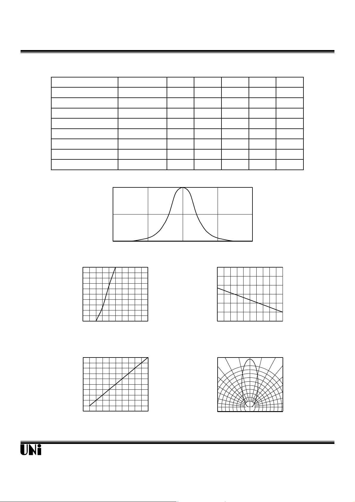
Optical-Electrical Characteristics
VS. FORWARD CURRENT
Parameter Test Conditions Symbol Min. Typ . Max. Unit
Radiant Intensity IF=20mA Ie 2.5 mW/sr
@ TA=25oC
Forward Voltage IF=50mA V
Reverse Current VR=5V I
F
R
Peak Wavelength IF=20mA λ 850 nm
Spectral Bandwidth IF=20mA ∆λ 30 nm
View Angle IF=20mA
Rise Time
Fall Time
IF=50mA
IF=50mA
2 θ
1/2
Tr 20 nsec
Tf 30 nsec
Typical Optical-Electrical Characteristic Curves
1
0.5
Relative Radiant Intensity
0
750 850 950
FIG.1 SPECTRAL DISTRIBUTION
100
80
60
40
20
Forward Current (mA)
0
0.8 1.2 1.6 2.0 2.4 2.8
Forward Voltage (V)
FIG.2 FORWARD CURRENT VS.
FORWARD VOLTAGE
5
4
=20mA
3
F
2
1
Value at I
Output Power Relative To
0
0 20 40 60 80 100
Forward Current (mA)
FIG.4 RELATIVE RADIANT INTENSITY
Wavelength (nm)
1.5 1.8 V
10 µΑ
35 deg .
3.0
2.5
=20mA
F
2.0
1.5
1.0
0.5
0.0
-40 -20 0 20 40 60
Output Power To Value I
Relative Radiant Intensity
Ambient Temperature TA (oC )
FIG.3 RELATIVE RADIANT INTENSITY
VS. AMBIENT TEMPERATURE
0° 10° 20°
1.0
0.9
0.8
0.5 0.3 0.1 0.2 0.4 0.6
FIG.5 RADIATION DIAGRAM
30°
40°
50°
60°
70°
80°
90°
Unity Opto Technology Co., Ltd.
02/04/2002
 Loading...