

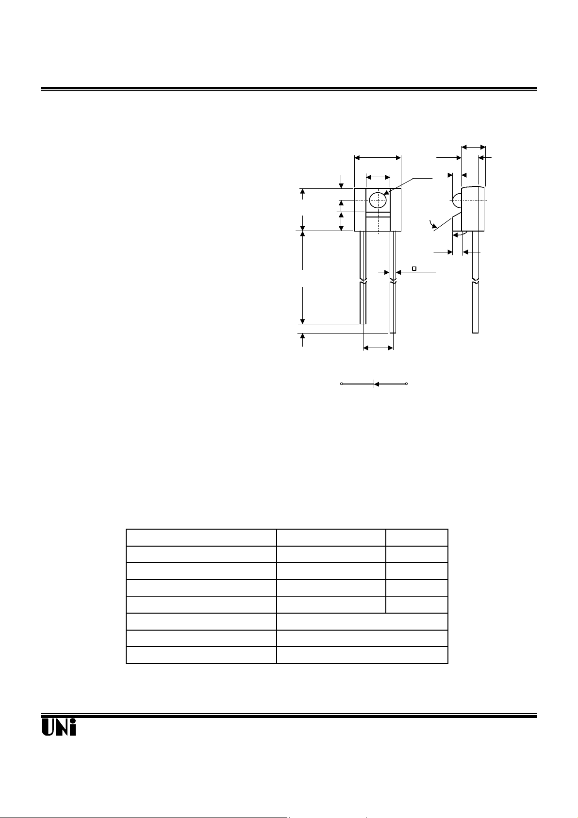
GaAs SIDE LOOK PACKAGE
INFRARED EMITTING DIODE
MIE-144G1
Description Package Dimensions
(.043)
60°
(.162)
(SEE NOTE 3)
(.156±.003)
(.048)
(.059)
(.100±.003)
The MIE-144G1 is a GaAs infrared emitting diode
Unit: mm( inches
molded in clear , lensed side looking package .
φ 1.50
(.020)
1.10
0.75
(.030)
0.80
(.032)
The MIE-144G1 provides a broad range of
intensity selection .
1.22
4.12
1.66±0.08
(.065±.003)
14.30MIN.
(.563)
4.00±0.08
1.80
1.80
(.071)
2- 0.5TYP.
Features
l Selected to specific on-line intensity and
radiant intensity ranges
l Low cost , plastic side looking package
l Mechanically and spectrally matched to
The MID-14422 of phototransistor .
1.0MIN.
(.039)
2.54±0.08
C A
Notes :
1. All dimensions are in millimeters.(inches).
2. Protruded resin under flange is 1.5 mm (0.059") max.
3. Lead spacing is measured where the leads emerge from the package.
1.50
(.059)
Absolute Maximum Ratings
Parameter Maximum Rating Unit
Power Dissipation 75 mW
Peak Forward Current 1 A
Continuos Forward Current 50 mA
Reverse Voltage 5 V
Operating Temperature Range
Storage Temperature Range
Lead Soldering Temperature
Unity Opto Technology Co., Ltd.
@ TA=25oC
-55oC to +100oC
-55oC to +100oC
260oC for 5 seconds
02/04/2002
MIE-144G1
Optical-Electrical Characteristics
VS. AMBIENT TEMPERATURE
Parameter Test Conditions Symbol Min. Typ . Max. Unit
Radiant Incidance
Forward Voltage
Reverse Current
Peak Wavelength
Spectral Bandwidth
Half View Angle
IF=20mA
IF=20mA V
VR=5V I
IF=20mA
IF=20mA
IF=20mA 2θ
Ee
F
R
λ
∆λ
1/2
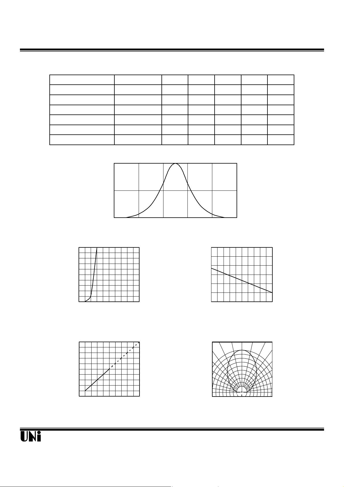
Typical Optical-Electrical Characteristic Curves
1
0.5
Relative Radiant Intensity
0
840 880 920 960 1000 1040
Wavelength (nm)
FIG.1 SPECTRAL DISTRIBUTION
- 0.6 -
-
- -
-
-
-
1.25 1.40 V
100
940
50
80
-
-
-
@ TA=25oC
mW/cm
2
µA
nm
nm
deg .
100
80
60
40
20
Forward Current (mA)
0
0 1.2 1.6 2.0 2.4 2.8
Forward Voltage (V)
FIG.2 FORWARD CURRENT VS.
FORWARD VOLTAGE
5
4
3
=20mA
F
2
1
Value at I
Output Power Relative To
0
0 20 40 60 80 100
Forward Current (mA)
FIG.4 RELATIVE RADIANT INTENSITY
VS. FORWARD CURRENT
3.0
=20mA
2.5
F
2.0
1.5
1.0
0.5
0.0
-40 -20 0 20 40 60
Output Power To Value I
Ambient Temperature TA (oC)
FIG.3 RELATIVE RADIANT INTENSITY
0° 10° 20°
30°
40°
1.0
0.9
0.8
Relative Radiant Intensity
0.5 0.3 0.1 0.2 0.4 0.6
FIG.5 RADIATION DIAGRAM
50°
60°
70°
80°
90°
Unity Opto Technology Co., Ltd.
02/04/2002
 Loading...