

Unitronics 1
Vision™ OPLC™
Installation Guide
Models V230/260/280/290 (Non-color Screens)
This guide provides basic information for Unitronics’ Models V230/260/280/290 (Non-color Screens).
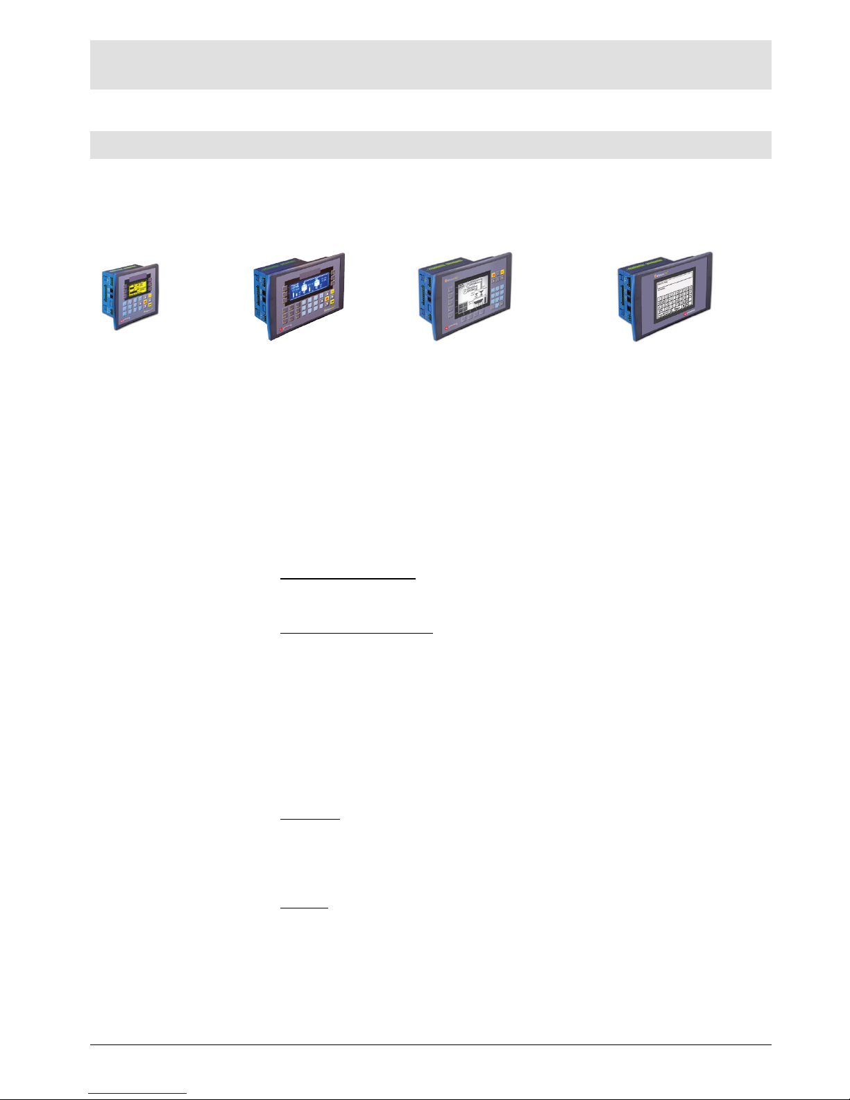
General Description
Vision OPLCs are programmable logic controllers that comprise an integral operating panel
containing a graphic LCD screen and a keyboard. All models offer the same PLC features.
Operating panel features differ according to model.
V230
LCD + Keyboard
V260
LCD + Keyboard
V280
Touchscreen + Keyboard
V290
Touchscreen only
Communications
2 serial ports: RS232 (COM1), RS232/RS485 (COM2)
1 CANbus port
The user can order and install an additional port. Available port
types are: RS232/RS485, and Ethernet
Communication Function Blocks include: SMS, GPRS, MODBUS
serial/IP Protocol FB enables PLC to communicate with almost
any external device, via serial or Ethernet communications
I/O Options
Vision supports digital, high-speed, analog, weight and temperature
measurement I/Os via:
Snap-in I/O Modules
Plug into the back of the controller to provide an on-board I/O
configuration
I/O Expansion Modules
Local or remote I/Os may be added via expansion port or CANbus
Information Mode
This mode enables you to:
View & Edit operand values, COM port settings, RTC and scr
een
c
ontrast/brightness settings
Calibrate the touchscreen
Stop, initialize, and reset the PLC
To enter Information Mode, press the <i> button for several seconds.
Programming
Software,
& Utilities
The Unitronics Setup CD contains VisiLogic freeware and other utilities
VisiLogic
Easily configure hardware and write both HMI and Ladder control
applications; the Function Block library simplifies complex tasks
such as PID. Write your application, and then download it to the
controller via the programming cable included in the kit
Utilities
These include UniOPC server, Remote Access for remote
programming and diagnostics, and DataXport for run-time data logging
To learn how to use and program the controller, as well as use utilities such
as Remote Access, refer to the VisiLogic Help system.

Vision™ OPLC™ Models V230/260/280/290 (Non-color Screens)
2 Unitronics
Operand Types
Memory Bits 4096 │Memory Integers, 16-bit, 2048 │Long Integers, 32-bit,
256 │Double Word, 32-bit unsigned, 64 │Memory Floats, 32-bit, 24 │
Timers, 32-bit, 192 │Counters, 16-bit, 24
Additional product documentation is in the Technical Library, located at www.unitronics.com
.
Technical support is available at the site, and from support@unitronics.com.
Kit Contents
Vision controller Programming cable + RS232 adapter
Mounting brackets (x4)
Grounding hardware
3 pin power supply connector
Rubber seal
5 pin CANbus connector
Extra set of keyboard slides, according to model
CANbus network termination resistor Unitronics’ Setup CD
Alert Symbols and General Restrictions
When any of the following symbols appear, read the associated information carefully.
Symbol Meaning Description
D
anger The identified danger causes physical and property damage.
Warning The identified danger could cause physical and property damage.
Caution Caution Use caution.
Before using this product, the user must read and understand this document
All examples and diagrams are intended to aid understanding, and do not guarantee operation
Unitronics accepts no responsibility for actual use of this product based on these examples
Please dispose of this product according to local and national standards and regulations
Only qualified service personnel should open this device or carry out repairs
Failure to comply with appropriate safety guidelines can cause severe injury or property damage
Do not attempt to use this device with parameters that exceed permissible levels
To avoid damaging the system, do not connect/disconnect the device when power is on
Environmental Considerations
Do not install in areas with: excessive or conductive dust, corrosive or flammable gas,
moisture or rain, excessive heat, regular impact shocks or excessive vibration, i
n
ac
cordance with the standards given in the product’s technical specification sheet
Ventilation: 10mm space required between controller’s top/bottom edges & enclosure walls
Do not place in water or let water leak onto the unit
Do not allow debris to fall inside the unit during installation
Install at maximum distance from high-voltage cables and power equipment

Installation Guide
Unitronics 3
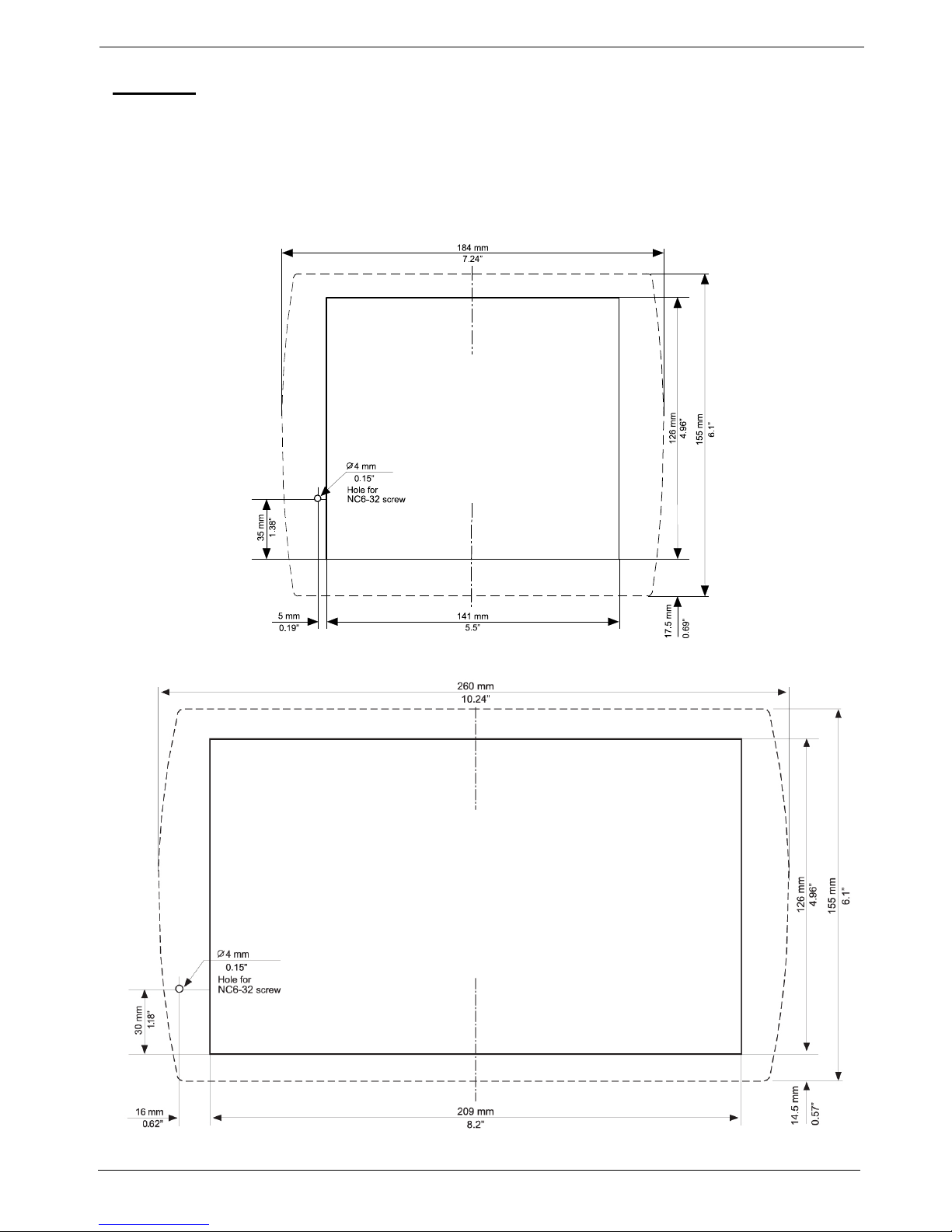
Mounting
Dimensions
V230
V260/280/290
Vision™ OPLC™ Models V230/260/280/290 (Non-color Screens)
4 Unitronics
Mounting
Before you begin, note that:
The mounting panel cannot be more than 5 mm thick
To minimize electromagnetic interference, mount the controller on a metal panel
and
ear
th the power supply according to the details on page 5
1. M
ake a panel cut-out that suits your model controller.
V230 Cut-out Dimensions
V260/280/290 Cut-out Dimensions

Installation Guide
Unitronics 5
2. If you mount the controller on a metal panel, earth the power supply:
a. Bore a hole to suit the NC6-32 screw supplied with the kit.
b. Scrape panel paint away from the contact area to ensure a conductive
connection.
c. Drive the screw into the hole.
d. Place the following hardware screw’s shank, in the order shown in the
accompanying figure: washer, ring cable shoe, second washer, spring,
and nut.
Pay Attention:
The wire used to earth the power supply must not exceed 10 cm in length
if your conditions do not permit this, do not earth the power supply.
Make sure that the metal panel is properly earthed.
3. Slide the controller into the cut-out, ensuring
that the rubber seal is in place.
4. Push the 4 mounting brackets into their slots
on the sides of the controller as shown in the
figure to the right.
5. Tighten the bracket screws against the
panel. Hold the bracket securely against the
unit while tightening the screw.
6. When properly mounted, the controller is squarely situated in the panel cut-out as shown below.
5BWiring: General
This equipment is designed to operate only in SELV/PELV/Class 2/Limited Power
environments
All power supplies in the system must include double insulation. Power supply outputs
must be rated as SELV/PELV/Class 2/Limited Power.
Do not connect either the ‘Neutral or ‘Line’ signal of the 110/220VAC to device’s 0V pin.
Do not touch live wires.
All wiring activities should be performed while power is OFF.
Unused pins should not be connected. Ignoring this directive may damage the device
Caution
To avoid damaging the wire, do not exceed a maximum torque of 0.5 N·m
(5 kgf·cm)
Do not use tin, solder, or any substance on stripped wire that might cause the wire
strand to break

Vision™ OPLC™ Models V230/260/280/290 (Non-color Screens)
6 Unitronics
Use crimp terminals for wiring; use 26-14 AWG wire (0.13 mm 2–2.08 mm2).
1. Strip the wire to a length of 7±0.5mm (0.250–0.300”).
2. Unscrew the terminal to its widest position before inserting a wire.
3. Insert the wire completely into the terminal to ensure a proper connection.
4. Tighten enough to keep the wire from pulling free.
Wiring Guidelines
Use separate wiring ducts for each of the following groups:
Group 1: Low voltage I/O and supply lines, communication lines.
Group 2: High voltage Lines, Low voltage noisy lines like motor driver outputs.
Separate these groups by at least 10cm (4"). If this is not possible, cross the ducts at a 90˚angle.
For proper system operation, all 0V points in the system should be connected to the
system 0V supply rail.
Earthing the Controller
To maximize system performance, avoid electromagnetic interference as follows:
Use a metal cabinet.
Connect the functional earth terminal ( ) as described on page 5.
Use only the grounding cable provided with the controller.
Connect the 0V terminal to the earth ground of the system at one point, preferably as near to
the controller as possible.
Power Supply
The controller requires an external 12 or 24VDC power supply. The permissible input voltage
range is 10.2-28.8VDC, with less than 10% ripple.
You must use an external circuit protection device
Install an external circuit breaker. Guard against short-
circuiting in external wiring
Double-check all wiring before turning on the power
supply
In the event of voltage fluctuations or non-conformity to
voltage power supply specifications, connect the
device to a regulated power supply
Communication Ports
Turn off power before making communications connections
Signals are related to the controller’s 0V; this is the same 0V used by the power
supply
Caution
Always use the appropriate port adapters
The serial ports are not isolated. If the controller is used with a non-isolated external
device, avoid potential voltage that exceeds ± 10V

Installation Guide
Unitronics 7
Serial Communications
This series comprises 2 RJ-11-type serial ports and a CANbus port.
COM1 is RS232 only. COM2 may be set to either RS232 or RS485 via jumper as described below.
By default, the port is set to RS232.
Use RS232 to download programs from a PC, and to communicate with serial devices and
applications, such as SCADA.
Use RS485 to create a multi-drop network containing up to 32 devices.
Caution COM1 & 2 are not isolated
Pinouts
To connect a PC to a port that is set to RS485, remove the RS485 connector, and connect the PC
to the PLC via the programming cable. Note that this is possible only if flow control signals are not
used (which is the standard case).
RS232
RS485**
Controller Port
Pin #
Description
Pin #
Description
Pin #1
1* DTR signal
1 A signal (+)
2 0V reference
2 (RS232 signal)
3 TXD signal
3 (RS232 signal)
4 RXD signal
4 (RS232 signal)
5 0V reference
5 (RS232 signal)
6* DSR signal
6 B signal (-)
*Standard programming cables do not provide connection points for pins 1 and 6.
** When a port is adapted to RS485, Pin 1 (DTR) is used for signal A, and Pin 6 (DSR) signal
is used for signal B.
RS232 to RS485: Changing Jumper Settings
The port is set to RS232 by factory default.
To change the settings, first remove the Snap-in I/O Module, if one is installed, and then set the
jumpers according to the following table.
Note:
For V230/V280 modules only there is a small window as described on page 5 for jumper
setting so there is no need to open the controller.
Before you begin, touch a grounded object to discharge any electrostatic charge
Before removing a Snap-in I/O Module or opening the controller, you must turn off the power
RS232/RS485 Jumper Settings
Jumper
1 2 3
4
RS232*
A A A A
RS485
B B B
B
RS485
Termination
A A B B
*Default factory setting.

Vision™ OPLC™ Models V230/260/280/290 (Non-color Screens)
8 Unitronics
Removing a Snap-in I/O Module
1. Locate the four buttons on the sides of the module, two on either side.
2. Press the buttons and hold them down to open the locking mechanism.
3. Gently rock the module from side to side, easing the module from the controller.
Opening and Closing the Controller (Except for V230/V280)
1. Locate the slots on the sides of the controller.
2. Open the controller by inserting a flat-bladed screwdriver into the slots located on the side of the
controller, then carefully prying off the rear panel.
3. Locate the jumpers, and then change the settings as required. Settings are shown on page 7
4. Close the controller by snapping the plastic cover back in its place.
Re-installing a Snap-in I/O Module
1. Line the circular guidelines on the controller up with the guidelines on the Snap-in I/O Module as
shown below.
2 Apply even pressure on all 4 corners until you hear a distinct ‘click’. The module is now installed.
Check that all sides and corners are correctly aligned.

Installation Guide
CANbus
121
terminating
resistor
121
terminating
resistor
Circuit
protection
device
+
-
24V Power
Supply
-V
L
H
+V
PE
-V
L
H+VPE
-V
L
H
+V
PE
These controllers comprise a CANbus port. Use this
to create a decentralized control network using one
of the following CAN protocols:
CANopen: 127 controllers or external
devices
Unitronics’ proprietary UniCAN: 60
controllers, (512 data bytes per scan)
The CANbus port is galvanically isolated.
CANbus Wiring
Use twisted-pair cable. DeviceNet® thick shielded
twisted pair cable is recommended.
Network terminators: These are supplied with
the controller. Place terminators at each end of the
CANbus network.
Resistance must be set to 1%, 121Ω, 1/4W.
Connect ground signal to the earth at only one
point, near the power supply.
The network power supply need not be at the end of
the network.
CANbus Connector
Samara
tel. +7 846 273 95 85
samara@klinkmann.spb.ru
Yekaterinburg
tel. +7 343 287 19 19
yekaterinburg@klinkmann.spb.ru
St. Petersburg
tel. +7 812 327 3752
klinkmann@klinkmann.spb.ru
Moscow
tel. +7 495 641 1616
moscow@klinkmann.spb.ru
Helsinki
tel. +358 9 540 4940
automation@klinkmann.
Vilnius
tel. +370 5 215 1646
post@klinkmann.lt
Riga
tel. +371 6738 1617
klinkmann@klinkmann.lv
Мinsk
tel. +375 17 200 0876
minsk@klinkmann.com
Tallinn
tel. +372 668 4500
klinkmann.est@klinkmann.ee
Кiev
tel. +38 044 495 33 40
klinkmann@klinkmann.kiev.ua
 Loading...