

Page 1

Unitronics
1
UniStream Remote I/O
User Manual
Revision 2.10
April, 2019
Page 2

4/19
Unitronics
2
Contents
About UniStream® Remote I/O ....................................................................................................................................................... 7
UniStream Remote I/O and Uni-I/O modules ............................................................................................................................... 7
Unitronics Remote I/O Models ......................................................................................................................................................... 8
Adapter ......................................................................................................................................................................................... 8
Digital Inputs ................................................................................................................................................................................ 8
Encoder / High Speed Counters .................................................................................................................................................... 8
Digital Outputs .............................................................................................................................................................................. 8
Relay ............................................................................................................................................................................................. 8
Analog Inputs 12 bit ..................................................................................................................................................................... 9
Analog Inputs 16 bit ..................................................................................................................................................................... 9
Analog Outputs 12 bit ................................................................................................................................................................... 9
Analog Outputs 16 bit ................................................................................................................................................................... 9
Temperature ................................................................................................................................................................................ 10
Power .......................................................................................................................................................................................... 10
Spare Parts .................................................................................................................................................................................. 10
Environmental ............................................................................................................................................................................. 10
URB-TCP (URB-TCP) – UniStream Remote IO Ethernet Adapter ............................................................................................... 11
General restrictions ..................................................................................................................................................................... 11
Environmental Considerations .................................................................................................................................................... 11
Dimensions ................................................................................................................................................................................. 11
Installation - DIN-Rail Module Mounting .................................................................................................................................. 12
How to Remove the Adapter Module from the DIN-Rail ........................................................................................................... 13
How to remove the RTB (Removable Terminal Block) from the I/O module ........................................................................... 13
How to connect the I/O modules ................................................................................................................................................ 14
Specifications .............................................................................................................................................................................. 15
Wiring Diagram .......................................................................................................................................................................... 16
RJ45 Socket ............................................................................................................................................................................ 16
IP Address Setup using BOOTP Server .................................................................................................................................. 17
Editing the IP defaults............................................................................................................................................................. 17
Selecting the IP Configuration Method .................................................................................................................................. 17
Configuring IP using Unitronics BOOTP Server........................................................................................................................ 18
LED Indicators ............................................................................................................................................................................ 21
MOD (Module Status LED).................................................................................................................................................... 21
LINK (Physical Connection LED) .......................................................................................................................................... 22
ACTIVE (Exchange Data/Traffic Present LED) .................................................................................................................... 22
IOS LED (Extension Module Status LED) ............................................................................................................................. 22
Field Power, System Power LED (Field Power, System Power Status LED) ........................................................................ 22
URD-0800 (DI08) - 8 Digital Inputs (sink or source) ..................................................................................................................... 23
1. Wiring Diagram ................................................................................................................................................................. 24
2. LED Indicators .................................................................................................................................................................. 25
URD-1600-8 (DI168) - 16 Digital Inputs (Sink / Source) .............................................................................................................. 26
1. Wiring Diagram ................................................................................................................................................................. 27
Page 3

Unitronics
3
2. LED Indicators ........................................................................................................................................................................ 28
URD-3200-4 (DI324) - 32 Digital Inputs (Sink / Source) .............................................................................................................. 29
1. Wiring Diagram ................................................................................................................................................................. 30
2. LED Indicators .................................................................................................................................................................. 31
URD-0400B (DI04B) - 4 Digital Inputs ......................................................................................................................................... 32
1. Wiring Diagram ................................................................................................................................................................. 33
2. LED Indicators .................................................................................................................................................................. 34
URD-0400C (DI04C) - 4 Digital Inputs ......................................................................................................................................... 35
1. Wiring Diagram ................................................................................................................................................................. 36
2. LED Indicators .................................................................................................................................................................. 37
URD-0200E (DI02E) - 2 High Speed Counters / Encoder Inputs .................................................................................................. 38
1. Wiring Diagram ................................................................................................................................................................. 39
2. LED Indicators .................................................................................................................................................................. 40
URD-0200D (DI02D) - 2 High Speed Counters / Encoder Inputs ................................................................................................. 41
1. Wiring Diagram ................................................................................................................................................................. 42
2. LED Indicators .................................................................................................................................................................. 43
URD-0008CH (DO08CH) - 8 Digital Outputs (Source) ................................................................................................................. 44
1. Wiring Diagram ................................................................................................................................................................. 45
2. LED Indicators .................................................................................................................................................................. 46
URD-0008CI (DO08CI) - 8 Digital Outputs, (Source) ................................................................................................................... 47
1. Wiring Diagram ................................................................................................................................................................. 48
2. LED Indicators .................................................................................................................................................................. 49
URD-0016CG-8 (DO16C8) - 16 Digital Outputs, (Source) ........................................................................................................... 50
1. Wiring Diagram ................................................................................................................................................................. 51
2. LED Indicators .................................................................................................................................................................. 52
URD-0032CG-4 (DO32C4) - 32 Digital Outputs, (Source) ........................................................................................................... 53
1. Wiring Diagram ................................................................................................................................................................. 54
2. LED Indicators .................................................................................................................................................................. 55
URD-0008NH (DO08NH) - 8 Digital Outputs (Sink) .................................................................................................................... 56
1. Wiring Diagram ................................................................................................................................................................. 57
2. LED Indicators .................................................................................................................................................................. 58
URD-0008NI (DO08NI) - 8 Digital Outputs, (Sink) ...................................................................................................................... 59
1. Wiring Diagram ................................................................................................................................................................. 60
2. LED Indicators .................................................................................................................................................................. 61
URD-0016NG-8 (DO16N8) - 16 Digital Outputs, (Sink) .............................................................................................................. 62
1. Wiring Diagram ................................................................................................................................................................. 63
2. LED Indicators .................................................................................................................................................................. 64
URD-0032NG-4 (DO32N4) - 32 Digital Outputs, (Sink) .............................................................................................................. 65
1. Wiring Diagram ................................................................................................................................................................. 66
2. LED Indicators .................................................................................................................................................................. 67
URD-0004RH (DO04RH) - 4 Relay Outputs ................................................................................................................................. 68
1. Wiring Diagram ................................................................................................................................................................. 69
2. LED Indicators .................................................................................................................................................................. 70
URD-0004SK (DO04SK) - 4 Solid State Relay ............................................................................................................................. 71
Page 4

4/19
Unitronics
4
1. Wiring Diagram ................................................................................................................................................................. 72
2. LED Indicators .................................................................................................................................................................. 73
URD-0004SM (DO04SM) - 4 Solid State Relay ............................................................................................................................ 74
1. Wiring Diagram ................................................................................................................................................................. 75
2. LED Indicators .................................................................................................................................................................. 76
URD-0004SN (DO04SN) - 4 Solid State Relay ............................................................................................................................. 77
1. Wiring Diagram ................................................................................................................................................................. 78
2. LED Indicators .................................................................................................................................................................. 79
URA-0400O (AI04O) - 4 Current Inputs ........................................................................................................................................ 80
1. Wiring Diagram ................................................................................................................................................................. 81
2. LED Indicators .................................................................................................................................................................. 82
URA-0800O (AI08O) - 8 Current Inputs ........................................................................................................................................ 83
1. Wiring Diagram ................................................................................................................................................................. 84
2. LED Indicators .................................................................................................................................................................. 85
URA-1600O-8 (AI16O8) - 16 Analog Current Inputs 12bit........................................................................................................... 86
1. Wiring Diagram ................................................................................................................................................................. 87
2. LED Indicators .................................................................................................................................................................. 88
URA-0400P (AI04P) - 4 Analog Voltage Inputs 12bit ................................................................................................................... 89
1. Wiring Diagram ................................................................................................................................................................. 90
2. LED Indicators .................................................................................................................................................................. 91
URA-0800P (AI08P) - 8 Analog Voltage Inputs 12bit ................................................................................................................... 92
1. Wiring Diagram ................................................................................................................................................................. 93
2. LED Indicators .................................................................................................................................................................. 94
URA-1600P-8 (AI16P8) - 16 Analog Voltage Inputs 12bit ........................................................................................................... 95
1. Wiring Diagram ................................................................................................................................................................. 96
URA-0400T (AI04T) - 4 Analog Current Inputs 16bit ................................................................................................................... 98
1. Wiring Diagram ................................................................................................................................................................. 99
2. LED Indicators ................................................................................................................................................................ 100
URA-1600T-8 (AI16U8) - 16 Analog Current Inputs 16bit ......................................................................................................... 101
1. Wiring Diagram ............................................................................................................................................................... 102
2. LED Indicators ...................................................................................................................................................................... 103
URA-0400U (AI04U) - 4 Analog Voltage Inputs 16bit ............................................................................................................... 104
1. Wiring Diagram ............................................................................................................................................................... 105
2. LED Indicators ................................................................................................................................................................ 106
URA-1600U-8 (AI16U8) - 16 Analog Voltage Inputs 16bit ........................................................................................................ 107
1. Wiring Diagram ............................................................................................................................................................... 108
2. LED Indicators ................................................................................................................................................................ 109
URA-0004W (AO04W) - 4 Analog Current Outputs 12bit .......................................................................................................... 110
1. Wiring Diagram ............................................................................................................................................................... 111
2. LED Indicators ................................................................................................................................................................ 112
URA-0008W (AO08W) - 8 Analog Current Outputs 12bit .......................................................................................................... 113
1. Wiring Diagram ............................................................................................................................................................... 114
2. LED Indicators ................................................................................................................................................................ 115
Page 5

Unitronics
5
URA-0004X (AO04X) - 4 Analog Voltage Outputs 12bit ........................................................................................................... 116
1. Wiring Diagram ............................................................................................................................................................... 117
2. LED Indicators ................................................................................................................................................................ 118
URA-0008X (AO08X) - 8 Analog Voltage Outputs 12bit ........................................................................................................... 119
1. Wiring Diagram ............................................................................................................................................................... 120
2. LED Indicators ................................................................................................................................................................ 121
URA-0016X-8 (AO16X8) - 16 Analog Voltage Outputs 12bit .................................................................................................... 122
1. Wiring Diagram ............................................................................................................................................................... 123
2. LED Indicators ................................................................................................................................................................ 124
URA-0004Y (AO04Y) - 4 Analog Current Outputs 16bit ............................................................................................................ 125
1. Wiring Diagram ............................................................................................................................................................... 126
2. LED Indicators ................................................................................................................................................................ 127
URA-0004Z (AO04Z) - 4 Analog Voltage Outputs 16bit ............................................................................................................ 128
1. Wiring Diagram ............................................................................................................................................................... 129
2. LED Indicators ................................................................................................................................................................ 130
URA-0016Z-8 (AO16Z8) - 16 Analog Voltage Outputs 16bit ..................................................................................................... 131
1. Wiring Diagram ............................................................................................................................................................... 132
2. LED Indicators ................................................................................................................................................................ 133
URS-04RT (S04RT) - 4 RTD / Resistance ................................................................................................................................... 134
1. Wiring Diagram ............................................................................................................................................................... 135
2. LED Indicators ................................................................................................................................................................ 136
URS-08RT-2 (S08RT2) - 8 RTD / Resistance .............................................................................................................................. 137
1. Wiring Diagram ............................................................................................................................................................... 138
2. LED Indicators ................................................................................................................................................................ 139
URS-04TC (S04TC) - 4 Thermocouple / mV ............................................................................................................................... 140
1. Wiring Diagram ............................................................................................................................................................... 141
2. LED Indicators ................................................................................................................................................................ 142
URS-08TC-2 (S08TC2) - 8 Thermocouple / mV ......................................................................................................................... 143
1. Wiring Diagram ............................................................................................................................................................... 144
2. LED Indicators ................................................................................................................................................................ 145
URP-PS24V (PS24) - Input 24VDC, Output system Power 5VDC/1A ....................................................................................... 146
Usage ........................................................................................................................................................................................ 146
1. Wiring Diagram ............................................................................................................................................................... 147
2. LED Indicators ................................................................................................................................................................ 148
URP-C0V0V (PC00) - 8 0VDC Potential Distribution ................................................................................................................ 149
1. Wiring Diagram ............................................................................................................................................................... 150
2. LED Indicators ................................................................................................................................................................ 151
URP-C24V24V (PC2424) - 8 24VDC Potential Distribution ...................................................................................................... 152
1. Wiring Diagram ............................................................................................................................................................... 153
2. LED Indicators ................................................................................................................................................................ 154
URP-C0V24V (PC024) - 4 24VDC, 4 0VDC Potential Distribution ........................................................................................... 155
1. Wiring Diagram ............................................................................................................................................................... 156
2. LED Indicators ................................................................................................................................................................ 157
URP-PDIST (PPDIST) - External Universal Power Distribution ................................................................................................. 158
Page 6

4/19
Unitronics
6
1. Wiring Diagram ............................................................................................................................................................... 159
2. LED Indicators ................................................................................................................................................................ 160
URP-SHIELD (PSHLD) - External Universal Shield Distribution .............................................................................................. 161
1. Wiring Diagram ............................................................................................................................................................... 162
2. LED Indicators ................................................................................................................................................................ 163
I/O Module Dimensions................................................................................................................................................................ 164
I/O Module (10RTB) ................................................................................................................................................................ 164
I/O Module (18RTB) ................................................................................................................................................................ 164
Page 7

Unitronics
7
About UniStream® Remote I/O
This line of remote Ethernet I/O is compatible with UniStream controllers. The line comprises an Ethernetbased Remote I/O adapter and I/O Remote modules.
You configure Remote I/Os in UniLogic, using the Hardware Configuration editor, and connect them to the
controller via Ethernet cable
A single UniStream Remote I/O adapter can support up to 63 12mm wide I/O modules. Each adapter
comprises two Ethernet ports; this enables users to link an adapter to a controller, and then daisy-chain
adapters to support up to 8 adapters per controller, increasing the total number of I/Os supported by a single
UniStream.
UniStream Remote I/O offer a broad range of modules; each module offers a different configuration of
analog and digital outputs.
Note that the exact number of I/Os that can be included per adapter is dependent on the specific I/O
connected to that specific adapter.
The adapter is limited to process 192 data bytes for inputs and 192 data bytes for outputs.
Each digital input/output point process data is 1 bit (minimum 1 byte per module if module data size is less
than 8 points) while each analog input/output is 2 bytes (8 inputs/outputs module will be 16 bytes of process
data).
UniStream Remote I/O and Uni-I/O modules
You may use both lines in the same application at the same time.
Since the two lines communicate via different protocols and physical connections:
They work independently of each other
You can use both lines with the same controller at the same time.
Note that the adapters and modules of each line are not interchangeable.
You may only use:
Uni-Local Expansion Adapters with Uni-I/O modules
UniStream Remote I/O Adapters with UniStream Remote I/O modules.
Page 8

4/19
Unitronics
8
Label
Article
Description
Ethernet
Ports
Support
Slots
Operating
Voltage
Operating
temperature
URB-TCP
URB-TCP
UniStream Remote IO
Ethernet Adapter
2
Up to 63
24VDC
-40°C to 70°C (-40°F to 158°F)
on 0.8A load
-40°C to 60°C (-40°F to 140°F)
on 1.5A load
Label
Article
Description
Number of IO
DI08
URD-0800
8 Digital inputs (sink or source), 10 RTB
8
DI168
URD-1600-8
16 Digital Inputs (Sink / Source),18 RTB
16
DI324
URD-3200-4
32 Digital Inputs (Sink / Source),40 IDC
32
DI04B
URD-0400B
4 Digital Inputs,10RTB
4
DI04C
URD-0400C
4 Digital Inputs,10RTB
4
Label
Article
Description
Number of IO
DI02E
URD-0200E
2 High Speed Counters / Encoder Inputs, 10RTB
2
DI02D
URD-0200D
2 High Speed Counters / Encoder Inputs, 10RTB
2
Label
Article
Description
Number of IO
DO08CH
URD-0008CH
8 Digital Outputs (Source), 10 RTB
8
DO08CI
URD-0008CI
8 Digital Outputs (Source), 10 RTB
8
DO16C8
URD-0016CG-8
16 Digital Outputs, (Source), 18 RTB
16
DO32C4
URD-0032CG-4
32 Digital Outputs, (Source), 40 IDC
32
DO08NH
URD-0008NH
8 Digital Outputs (Sink), 10 RTB
8
DO08NI
URD-0008NI
8 Digital Outputs, (Sink), 10 RTB
8
DO16N8
URD-0016NG-8
16 Digital Outputs, (Sink), 18 RTB
16
DO32N4
URD-0032NG-4
32 Digital Outputs, (Sink), 40 PIN IDC
32
Label
Article
Description
Number of IO
DO04RH
URD-0004RH
4 Relay, 10 RTB
4
DO04SK
URD-0004SK
4 Solid State Relay, 10 RTB
4
DO04SM
URD-0004SM
4 Solid State Relay, 10 RTB
4
DO04SN
URD-0004SN
4 Solid State Relay, 10 RTB
4
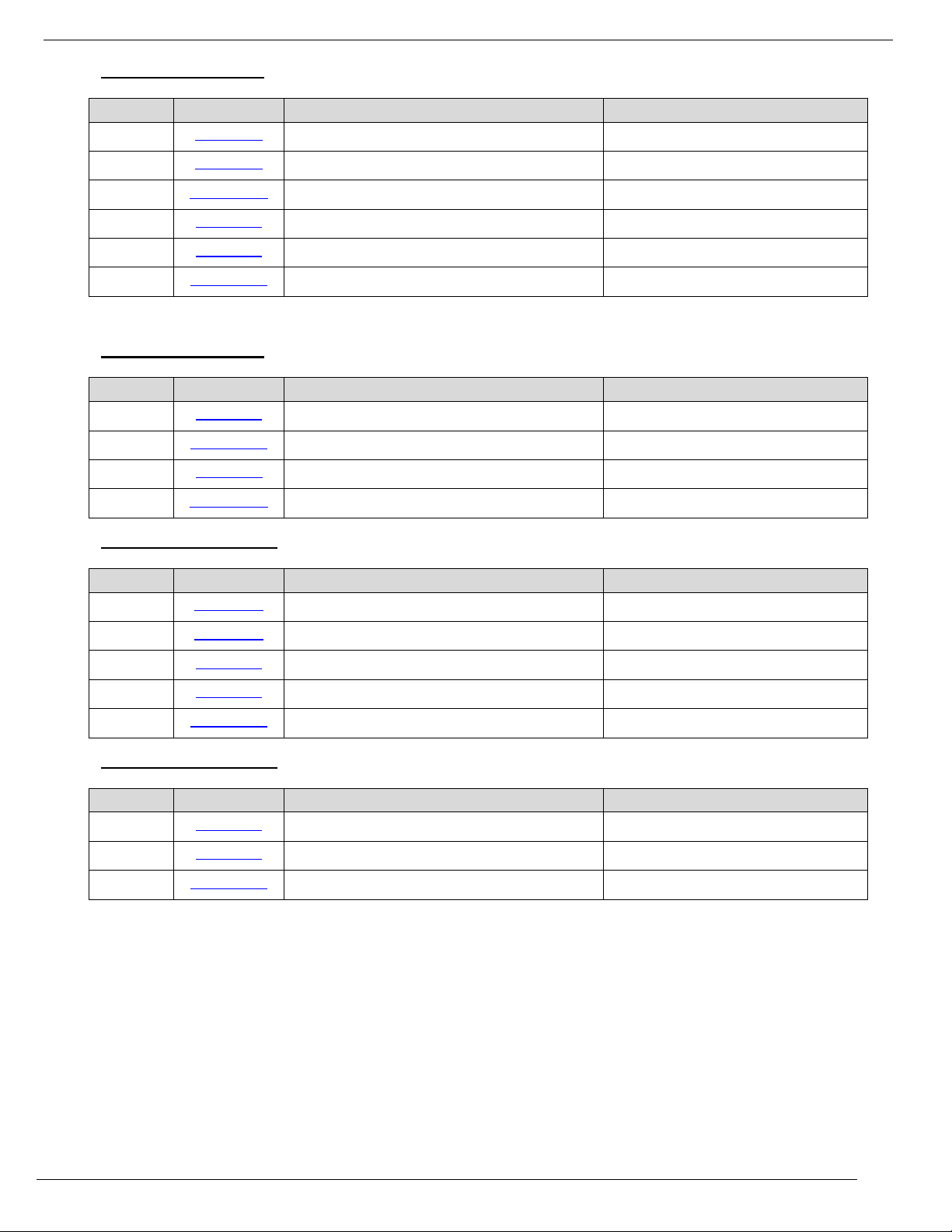
Unitronics Remote I/O Models
Adapter
Digital Inputs
Encoder / High Speed Counters
Digital Outputs
Relay
Page 9
Unitronics
9
Label
Article
Description
Number of IO
AI04O
URA-0400O
4 Analog Current Inputs, 10 RTB
4
AI08O
URA-0800O
8 Analog Current Inputs, 10 RTB
8
AI16O8
URA-1600O-8
16 Analog Current Inputs, 18 RTB
16
AI04P
URA-0400P
4 Analog Voltage Inputs, 10 RTB
4
AI08P
URA-0800P
8 Analog Voltage Inputs, 10 RTB
8
AI16P8
URA-1600P-8
16 Analog Voltage Inputs, 18 RTB
16
Label
Article
Description
Number of IO
AI04T
URA-0400T
4 Analog Current Inputs, 10 RTB
4
AI16T8
URA-1600T-8
16 Analog Current Inputs, 18 RTB
16
AI04U
URA-0400U
4 Analog Voltage Inputs, 10 RTB
4
AI16U8
URA-1600U-8
16 Analog Voltage Inputs, 18 RTB
16
Label
Article
Description
Number of IO
AO04W
URA-0004W
4 Analog Current Outputs, 10 RTB
4
AO08W
URA-0008W
8 Analog Current Outputs, 10 RTB
8
AO04X
URA-0004X
4 Analog Voltage Outputs, 10 RTB
4
AO08X
URA-0008X
8 Analog Voltage Outputs, 10 RTB
8
AO16X8
URA-0016X-8
16 Analog Voltage Outputs, 18 RTB
16
Label
Article
Description
Number of IO
AO04Y
URA-0004Y
4 Analog Current Outputs, 10 RTB
4
AO04Z
URA-0004Z
4 Analog Voltage Outputs, 10 RTB
4
AO16Z8
URA-0016Z-8
16 Analog Voltage Outputs, 18 RTB
16
Analog Inputs 12 bit
Analog Inputs 16 bit
Analog Outputs 12 bit
Analog Outputs 16 bit
Page 10

4/19
Unitronics
10
Temperature
Label
Article
Description
Number of IO
S04RT
URS-04RT
4 RTD / Resistance, 10 RTB
4
S08RT2
URS-08RT-2
8 RTD / Resistance, 20 PIN IDC
8
S04TC
URS-04TC
4 Thermocouple / Mv, 10 RTB
4
S08TC2
URS-08TC-2
8 Thermocouple / mV, 20 PIN IDC
8
Label
Article
Description
PS24
URP-PS24V
Adapter Additional System Power Expension, 1A
PC00
URP-C0V0V
8 0VDC Potential Distribution
PC2424
URP-C24V24V
8 24VDC Potential Distribution
PC024
URP-C0V24V
4 24VDC, 4 0VDC Potential Distribution
PPDIST
URP-PDIST
External Universal Power Distribution
PSHLD
URP-SHIELD
External Universal Shield Distribution
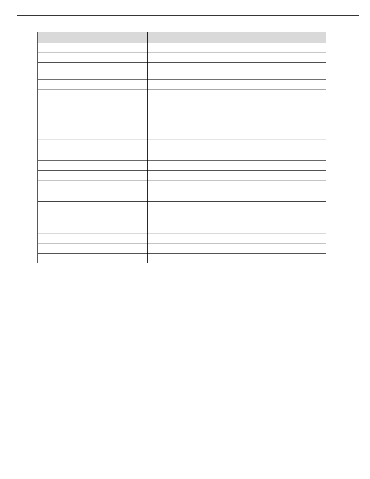
Article
Description
URB-END
Adapter End Module
URO-0105
10 Removable Terminal Block For I/O
URO-0106
18 Removable Terminal Block For I/O
URO-0101
10 Removable Terminal Block For Potential Distribution
URO-0102
10 Removable Terminal Block For External Power
URB-END
Adapter End Module
Protection
IP20, NEMA1
UL temperature
-20°C to 60°C (-4°F to 140°F)
Storage temperature
-40°C to 85°C (-40°F to 185°F)
Relative Humidity (RH)
5% to 90% (non-condensing)
Shock
IEC 60068-2-27
Vibration
IEC 60068-2-6
Mounting
DIN Rail
Certifications
CE , UL
Power
Spare Parts
Environmental
Page 11

Unitronics
11
URB-TCP (URB-TCP) – UniStream Remote IO Ethernet Adapter
General restrictions
All examples and diagrams are intended to aid understanding, and do not guarantee operation.
Unitronics accepts no responsibility for actual use of this product based on these examples.
Please dispose of this product according to local and national standards and regulations.
This product should be installed only by qualified personnel.
Environmental Considerations
Do not install in areas with: excessive or conductive dust, corrosive or flammable gas, moisture or rain,
excessive heat, regular impact shocks or excessive vibration, in accordance with the standards and
limitations given in the product’s technical specification sheet.
Do not place in water or let water leak onto the unit.
Do not allow debris to fall inside the unit during installation.
Install at maximum distance from high-voltage cables and power equipment.
Dimensions
Page 12

4/19
Unitronics
12
Installation - DIN-Rail Module Mounting
1. Press down the module lightly on the DIN rail until
the lower ridge click onto the rail.
Page 13

Unitronics
13
How to Remove the Adapter Module from the DIN-Rail
1. Pull the white locking latch. 2. Pull the module off the rail.
How to remove the RTB (Removable Terminal Block) from the I/O module
1. Pull out the plastic belt from the RTB. 2. Apply more force until the I/O module is pulled away from
the I/O module.
Page 14

4/19
Unitronics
14
How to connect the I/O modules
1. Line up the grooves on the module with the grooves on the adapter (if it is the first module) or on the
adjacent module, and slide the module into place as shown in the next image.
Page 15

Unitronics
15
Specifications
Items
Specification
Max. Expansion Module
Up to 63 slots
The adapter is limited to process 192 data bytes for inputs and 192 data bytes for
outputs.
Each digital input/output point process data is 1 bit (minimum 1 byte per module if
module data size is less than 8 points) while each analog input/output is 2 bytes
(8 inputs/outputs module will be 16 bytes of process data).
Max Length Bus Line
Up to 100m from Ethernet Hub/Switch with twisted CAT5 UTP/STP
Max. Nodes
Limited by Ethernet Specification.
Baud Rate
10/100Mbps, Auto-negotiation, Full duplex
Interface Connector
2 ports, RJ-45 socket
IP-Address Setup
DIP Switch or DHCP/BOOTP
IP-Address Range
xxx.xxx.xxx.1 ~ 253 (User area)
xxx.xxx.xxx.254 ~ 255 (Reserved for IAP Function)
Indicator
6 LEDs
1 Green/Red, Module Status (MOD)
1 Green, Physical Connection (LINK)
1 Green, Exchange Data/Traffic Present (ACTIVE)
1 Green/Red, Expansion I/O Module Statsus (IOS)
1 Green, System Power Status
1 Green, Field Power Status
2 LEDs (each RJ45 Connector)
1 Yellow, Link/Active
1 Green, Not used
For detailed indicators description, please follow the "LED indicators" section
bellow.
System Power
Supply voltage : 24VDC nominal
Supply voltage range : 15~32Vdc
Protection :
Output current limit (Min. 1.5A)
Reverse polarity protection
Power Dissipation
70mA typical @ 24VDC
Current for I/O Module
1.5A @ 5VDC
Isolation
System power to internal logic : Non-isolation
System power I/O driver : Isolation
Field Power
Supply voltage : 24VDC typical (Max. 32VDC)
Field Power Range is different depending on URI module series.
Refer to URI module`s specification.
Max. Current Field Power Contact
DC 10A Max
Weight
162g
Module Size
54mm x 99mm x 70mm
Page 16
4/19
Unitronics
16
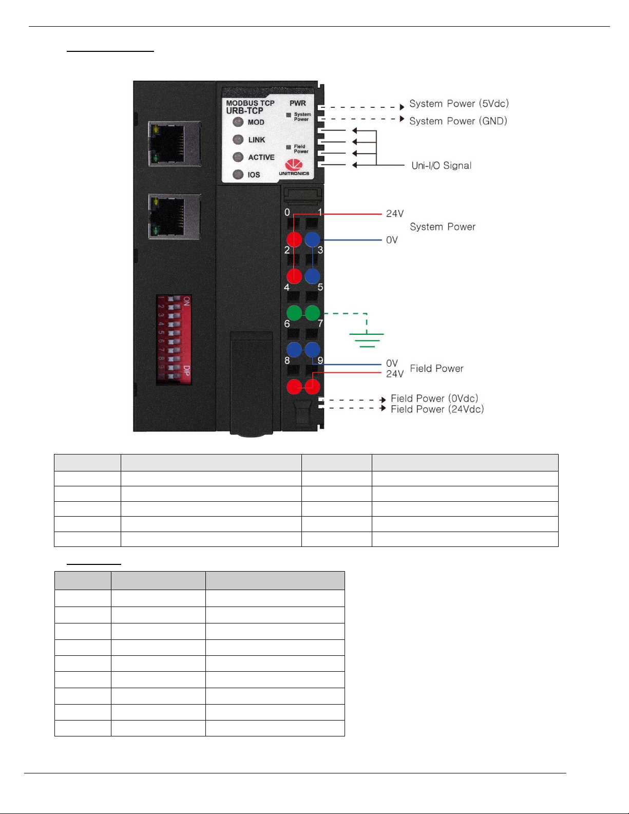
Wiring Diagram
Pin No.
Signal Description
Pin No.
Signal Description
0
System Power, 24V
1
System Power, Ground
2
System Power, 24V
3
System Power, Ground
4
F.G
5
F.G
6
Field Power, Ground
7
Field Power, Ground
8
Field Power, 24V
9
Field Power, 24V
RJ-45
Signal Name
Description
1
TD+
Transmit +
2
TD-
Transmit -
3
RD+
Receive +
4 - 5 - 6
RD-
Receive -
7 -
8 -
Case
Shield
RJ45 Socket
Page 17

Unitronics
17
IP Address Setup using BOOTP Server
The URB adapter IP defaults are:
Default IP: 192.168.100.100
Subnet mask: 255.255.255.0
Note that on the adapter, there is a sticker showing its MAC address.
Editing the IP defaults
There are two methods of changing the IP address:
Via UniLogic’s BOOTP Server
This is a utility accessible via the UniLogic ribbon
Via DIP switch
These are physical switches on the adapter
Selecting the IP Configuration Method
To enable the selected method, you must raise the appropriate DIP switch on the adapter. By factory default, the
adapter is supplied with all switches down.
Raise #9 to set IP via BOOTP Server:
Enables the adapter BOOTP/DHCP.
After power up, the adapter will send up to 20 consecutive BOOTP/DHCP request messages, one for
every 2 seconds.
In case that the BOOTP/DHCP server does not respond, the Adapter applies the latest saved IP
address.
Raise #10 to set IP via DIP switch:
You can then set the IP according to the description in the next table.
Page 18

4/19
Unitronics
18
URB Adapter DIP Switches
#
Role
Description
1
IP bit#0
Lowest IP Address octet when
Switch #10=ON (raised)
Example: XXX.XXX.XXX.IP
[XXX.XXX.XXX represents the last configured network address]
Example for full bitmap: XXX.XXX.XXX.100
Bit0
Bit1
Bit2
Bit3
Bit4
Bit5
Bit6
Bit7
DHCP
USE IP
OFF
OFF
ON
OFF
OFF
ON
ON
OFF
OFF
ON 2
IP bit#1
3
IP bit#2
4
IP bit#3
5
IP bit#4
6
IP bit#5
7
IP bit#6
8
IP bit#7
9
DHCP /
BOOTP
Enable DHCP / BOOTP
10
Use DIP IP
Value
Enable IP Address set by DIP Switches
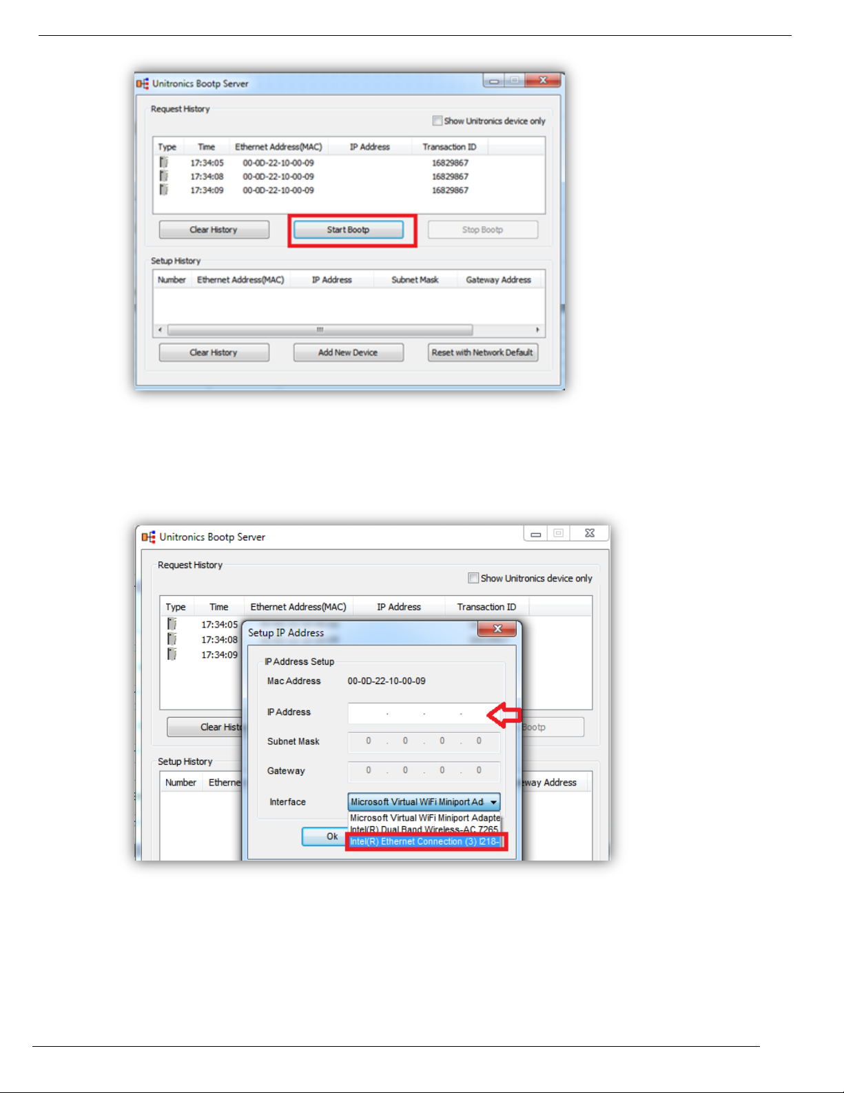
Configuring IP using Unitronics BOOTP Server
Before you can set the IP address of the Remote IO adaptor via Unitronics BOOTP Server, you must raise DIP #9
(check that #10 is down)
1. Power OFF the URB adapter.
2. Raise DIP switch #9 to enable DHCP / BOOTP.
3. In UniLogic, in the Solution Explorer, select the adapter; the ribbon will open the tab URB Remote I/O.
4. On the ribbon, click on Run BOOTP Server to open the utility.
5. Click Start BootP in the Unitronics BOOTP Server; the upper section displays Ethernet devices that
are in the network.
Page 19
Unitronics
19
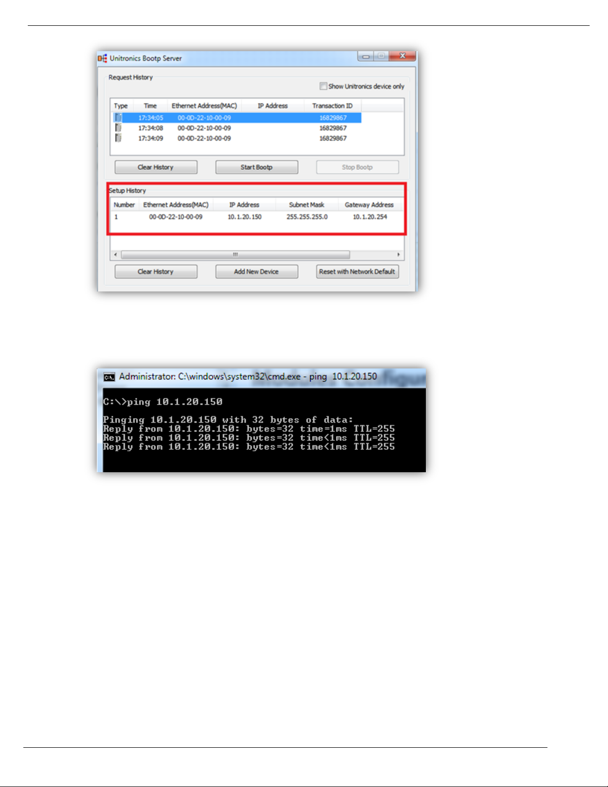
6. Power ON the URB adapter.
7. Locate the adapter’s MAC address and double-click on the row.
8. Enter the required IP address and select your PC Network card.
9. Click Ok. Now you should see the device in the bottom window including the IP address.
Page 20
4/19
Unitronics
20
10. Power cycle the adapter; turn it off and on.
11. Use Ping from command line to check that the IP address is replying.
12. If the adapter replies successfully, then power off the adapter (URB-TCP) and lower DIP switch #9 (set
to OFF).
13. Configure the adapter and IO modules in UniLogic and test.
Page 21
Unitronics
21
LED No.
LED Function /
Description
LED Color
MOD
Module Status
Green/Red
LINK
Physical Connection
Green
ACTIVE
Exchange Data/Traffic Present
Green
IOS
Extension Module Status
Green/Red
System Power
System Power Enable
Green
Field Power
Field Power Enable
Green
Status
LED
Indication
Not Powered
OFF
Not power is supplied to the unit.
Device Operational
Green
The unit is operating in normal condition.
Devicce in Standby
Flashing Green
The device needs commissioning due to configuration missing,
incomplete or incorrect.
Protocol Error
Green/Red Toggle
Protocol error such as watchodg error, etc.
Minor Fault
Flashing Red
Recoverable Fault.
- EEPROM checksum fault.
Unrecoverable Fault
Red
The device has an unrecoverable fault.
- Memory error or CPU watchdog error.
LED Indicators
MOD (Module Status LED)
Page 22
4/19
Unitronics
22
Status
LED
Indication
Not Powered or Not Linked
OFF
Device may not be powered
Adapter physical connected
Green
Adapter Ethernet Controller physically connected
Status
LED
Indication
Not Powered
OFF
Device is idle or may not be powered.
Adapter exchange data
Flashing Green
Adapter(slave) exchange data/Traffic present.
About 10msec flashing.
Status
LED
Indication
Not Powered
OFF
Device may not be powered.
No Expansion Module
Flashing Red
Adapter has no expansion module
Internal Bus Connection,
Run Exchanging I/O
Green
Exchanging I/O data.
Expansion Configuration Failed
Red
One or more expansion module occurred in fault state.
- Detected invalid expansion module ID.
- Overflowed Input/Output Size
- Too many expansion module
- Initialization failure
- Communication failure.
- Changed expansion module configuration.
- Mismatch vendor code between adapter and expansion module.
Status
LED
Indication
No field, System power
OFF
Not supplied 24VDC field power, 5VDC system power.
Supplied field, System power
Green
Supplied 24VDC field power, 5VDC system power.
LINK (Physical Connection LED)
ACTIVE (Exchange Data/Traffic Present LED)
IOS LED (Extension Module Status LED)
Field Power, System Power LED (Field Power, System Power Status LED)
Page 23
Unitronics
23
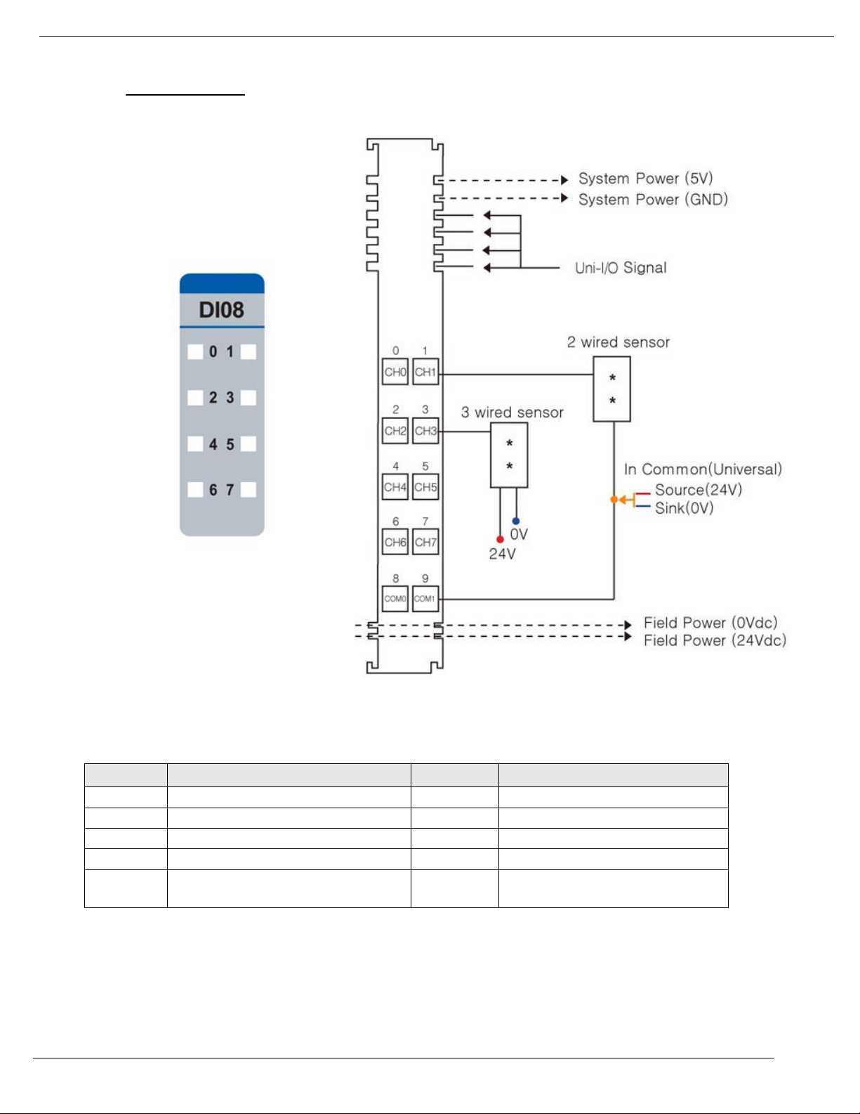
URD-0800 (DI08) - 8 Digital Inputs (sink or source)
Items
Specification
Inputs per module
8 Points Universal type
Indicators
8 Green Input state
ON–state Voltage
24VDC nominal
Min. 15VDC to Max. 32VDC
OFF-state voltage
8.3VDC @ 25 ºC (77°F)
ON-state current
3.03mA maximum/input @32VDC
Input Signal Delay
OFF to ON : 0.3ms Max
ON to OFF : 0.3ms Max
Input filter
Adjustable, up to 10ms
Nominal Input Impedance
10.2K ohm typical
COMMON Type
8 points / External 2COM (Universal)
Power dissipation
35mA maximum @ 5.0VDC
Isolation
I/O to Logic : Optocoupler Isolation
Field Power
Supply voltage : 24VDC nominal
Voltage range : 15 to 32VDC
Power dissipation : 0mA @ 24VDC
Wiring
I/O Cable Max. (AWG 14)
Weight
39g
Module Size
12mm x 99mm x 70mm
Operating temperature
-40°C to 70°C (-40°F to 158°F)
Page 24
4/19
Unitronics
24
Pin No.
Signal Description
Pin No.
Signal Description
0
Input 0
1
Input 1
2
Input 2
3
Input 3
4
Input 4
5
Input 5
6
Input 6
7
Input 7
8
Common(Sink Oper.0V /
Source Oper.24V)
9
Common(Sink Oper.0V /
Source Oper.24V)
1. Wiring Diagram
Page 25
Unitronics
25
LED No.
LED Function / Description
LED Color
0
Input 0
Green
1
Input 1
Green
2
Input 2
Green
3
Input 3
Green
4
Input 4
Green
5
Input 5
Green
6
Input 6
Green
7
Input 7
Green
Status
LED
Indication
No Signal
Off
Normal Operation
On Signal
Green
Normal Operation
2. LED Indicators
Page 26

4/19
Unitronics
26
URD-1600-8 (DI168) - 16 Digital Inputs (Sink / Source)
Items
Specification
Inputs per module
16 Points Universal Digital Type
Indicators
16 Green input state
ON–state Voltage
24VDC nominal
70°C (158°F) - Min. 15 VDC to Max. 28.8 VDC
60°C (140°F) - Min. 15 VDC to Max. 32 VDC
ON-state current
3.05mA maximum/input @32VDC
Input Signal Delay
OFF to ON : 0.3ms Max
ON to OFF : 0.3ms Max
Nominal Input Impedance
14.9K ohm typical
COMMON Type
16 points / 2 COM
Power dissipation
50mA maximum @ 5.0VDC
Isolation
I/O to Logic : Photocoupler Isolation
Field Power
Supply voltage : 24VDC nominal
Voltage range : 15 to 32VDC
Power dissipation : 0mA @ 32VDC
Wiring
I/O Cable Max. (AWG 18)
Weight
63g
Module Size
12mm x 109mm x 70mm
Operating temperature
-40°C to 70°C (-40°F to 158°F)
Page 27

Unitronics
27
Pin No.
Signal Description
Pin No.
Signal Description
0
Input 0
1
Input 1
2
Input 2
3
Input 3
4
Input 4
5
Input 5
6
Input 6
7
Input 7
8
Input 8
9
Input 9
10
Input 10
11
Input 11
12
Input 12
13
Input 13
14
Input 14
15
Input 15
16
Common(Sink Oper.0V / Source Oper.24V)
17
Common(Sink Oper.0V / Source Oper.24V)
1. Wiring Diagram
Page 28

4/19
Unitronics
28
2. LED Indicators
LED No.
LED Function / Description
LED Color
0
Input 0
Green
1
Input 1
Green
2
Input 2
Green
3
Input 3
Green
4
Input 4
Green
5
Input 5
Green
6
Input 6
Green
7
Input 7
Green
8
Input 8
Green
9
Input 9
Green
10
Input 10
Green
11
Input 11
Green
12
Input 12
Green
13
Input 13
Green
14
Input 14
Green
15
Input 15
Green
Status
LED
Indication
Not Signal
Off
Normal Operation
On Signal
Green
Normal Operation
Page 29

Unitronics
29
URD-3200-4 (DI324) - 32 Digital Inputs (Sink / Source)
Items
Specification
Inputs per module
32 Points Universal Digital Type
Indicators
32 Green Input Status LEDs
ON–state Voltage
24VDC nominal
Min. 15VDC ~ Max. 32VDC
ON-state current
3mA maximum/input @32VDC
Input Signal Delay
OFF to ON : 0.2ms Max
ON to OFF : 0.2ms Max
Nominal Input Impedance
10.2K ohm typical
COMMON Type
32 Point / External 8COM(Universal)
Power dissipation
55mA maximum @ 5.0VDC
Isolation
I/O to Logic : Photocoupler Isolation
Field Power
Supply voltage : 24VDC nominal
Voltage range : 15 to 32VDC
Power dissipation : 0mA @ 24VDC
Wiring
Module connector : HIF3BA-40D-2.54R
Weight
59g
Module Size
12mm x 109mm x 70mm
Operating temperature
-40°C to 70°C (-40°F to 158°F)
Page 30

4/19
Unitronics
30
in No.
Signal Description
Pin No.
Signal Description
0
Input 0
1
Input 1
2
Input 2
3
Input 3
4
Input 4
5
Input 5
6
Input l 6
7
Input 7
8
Input 8
9
Input 9
10
Input 10
11
Input 11
12
Input 12
13
Input 13
14
Input 14
15
Input 15
16
Common(Sink Oper.0V / Source Oper.24V)
17
Common(Sink Oper.0V Source Oper.24V)
18
NC
19
NC
20
Input 16
21
Input 17
22
Input 18
23
Input 19
24
Input 20
25
Input 21
26
Input 22
27
Input 23
28
Input 24
29
Input 25
30
Input 26
21
Input 27
32
Input 28
33
Input 29
34
Input 30
35
Input 31
36
Common(Sink Oper.0V / Source Oper.24V)
37
Common(Sink Oper.0V / Source Oper.24V)
38
NC
39
NC
1. Wiring Diagram
Page 31

Unitronics
31
2. LED Indicators
LED No.
LED Function / Description
LED Color
0
INPUT 0
Green
1
INPUT 1
Green
2
INPUT 2
Green
...
...
Green
31
INPUT 31
Green
Status
LED
Indication
No Signal
Off
Normal Operation
On Signal
Green
Normal Operation
Page 32
4/19
Unitronics
32
URD-0400B (DI04B) - 4 Digital Inputs
Items
Specification
Inputs per module
4 Points type
Indicators
4 Green input state
ON–state Voltage
120VAC nominal
Min. 85VAC to Max. 132VAC
ON-state current
7.5mA maximum/point @120VAC
Input Signal Delay
OFF to ON : 30ms @ 120VAC
ON to OFF : 130ms @ 120VAC
Nominal Input Impedance
17.5K ohm typical
COMMON Type
4 Points / 4 Common ( L2/N )
Power dissipation
30mA maximum @ 5.0VDC
Isolation
I/O to Logic : Photocoupler isolation
Field Power
Supply voltage : 24VDC nominal
Voltage range : 15 to 32VDC
(AC Power Not used)
Wiring
I/O Cable Max. 2.0(AWG 14)
Weight
57g
Module Size
12mm x 99mm x 70mm
Operating temperature
-40°C to 70°C (-40°F to 158°F)
Page 33

Unitronics
33
Pin No.
Signal Description
Pin No.
Signal Description
0
Input 0
1
Input 1
2
Input 2
3
Input 3
4
Input Common ( L2/N )
5
Input Common ( L2/N )
6
Input Common ( L2/N )
7
Input Common ( L2/N )
8
N.C 9 N.C
1. Wiring Diagram
Page 34

4/19
Unitronics
34
LED No.
LED Function / Description
LED Color
0
Input 0
Green
1
Input 1
Green
2
Input 2
Green
3
Input 3
Green
Status
LED
Indication
No Signal
Off
No Input Signal
On Signal
Green
Normal Operation
2. LED Indicators
Page 35

Unitronics
35
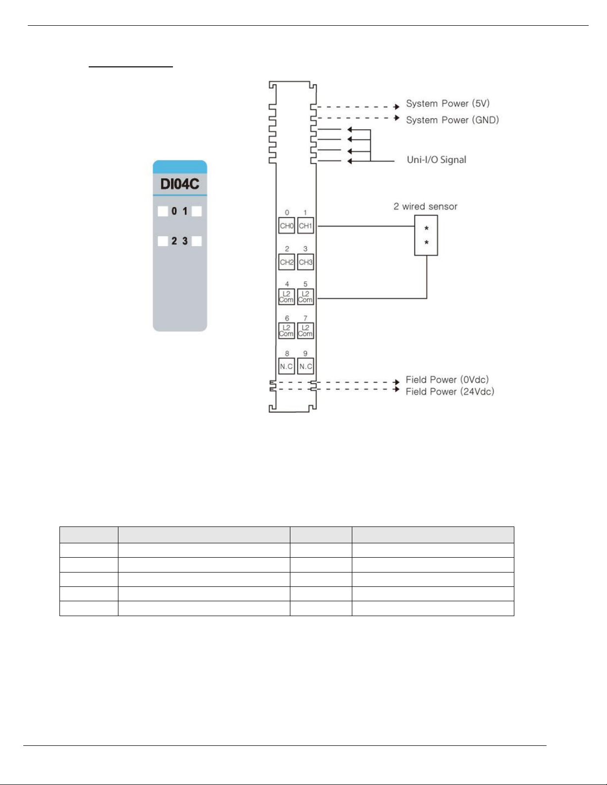
URD-0400C (DI04C) - 4 Digital Inputs
Items
Specification
Inputs per module
4 Points Sink type
Indicators
4 Green input state
ON–state Voltage
240VAC nominal
Min. 170VAC to Max. 264VAC
ON-state current
7.5mA maximum/point @120VAC
Input Signal Delay
OFF to ON : 30ms @ 240VAC
ON to OFF : 140ms @ 240VAC
Nominal Input Impedance
26.5K ohm typical
COMMON Type
4 Points / 4 Common ( L2/N )
Power dissipation
30mA maximum @ 5.0VDC
Isolation
I/O to Logic : Photocoupler isolation
Field Power
Supply voltage : 24VDC
Voltage range : 15 to 32VDC
(AC Power Not used)
Wiring
I/O Cable Max. 2.0 (AWG 14)
Weight
57g
Module Size
12mm x 99mm x 70mm
Operating temperature
-40°C to 60°C (-40°F to 140°F)
Page 36
4/19
Unitronics
36
Pin No.
Signal Description
Pin No.
Signal Description
0
Input 0
1
Input 1
2
Input 2
3
Input 3
4
Input Common ( L2/N )
5
Input Common ( L2/N )
6
Input Common ( L2/N )
7
Input Common ( L2/N )
8
N.C 9 N.C
1. Wiring Diagram
Page 37
Unitronics
37
LED No.
LED Function / Description
LED Color
0
Input 0
Green
1
Input 1
Green
2
Input 2
Green
3
Input 3
Green
Status
LED
Indication
No Signal
Off
No Input Signal
On Signal
Green
Normal Operation
2. LED Indicators
Page 38
4/19
Unitronics
38
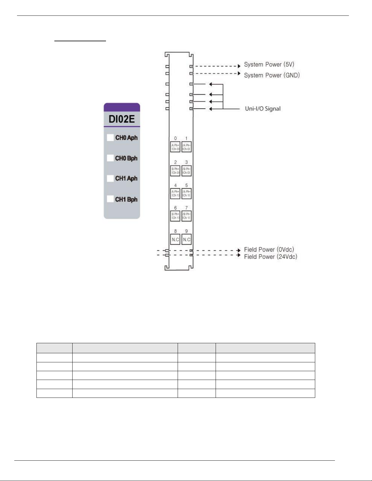
URD-0200E (DI02E) - 2 High Speed Counters / Encoder Inputs
Items
Specification
Number of Channel
2 Channels
- Encoder, High Speed Counter, Frequency measurement
Pulse width & Period measurement
Indicators
4 Green Terminal Input LEDs
Input Voltage
5 to 24VDC
Input Current
3.0mA@4.5VDC
4.0mA @ 24VDC
Min On-State Volt/Current
≥3.5VDC
Max Off-State Volt/Current
≤3.0VDC
Power dissipation
155mA maximum @ 5.0VDC
Isolation
I/O to Logic : Photocoupler isolation
I/O to Field Power : Non-Isolation
Field Power
Supply voltage : 24Vdc nominal
Voltage range : 18 to 32VDC
Wiring
I/O Cable Max. 2.0(AWG 14)
Weight
60g
Module Size
12mm x 90.5mm x 65mm
Operating temperature
-40°C to 70°C (-40°F to 158°F)
Page 39
Unitronics
39
Pin No.
Signal Description
Pin No.
Signal Description
0
Aph Input+ Ch# 0
1
/Aph Input - Ch# 0
2
Bph Input+ Ch# 0
3
/Bph Input - Ch# 0
4
Aph Input+ Ch# 1
5
/Aph Input - Ch# 1
6
Bph Input+ Ch# 1
7
/Bph Input - Ch# 1
8
N.C 9 N.C
1. Wiring Diagram
Page 40
4/19
Unitronics
40
LED No.
LED Function / Description
LED Color
0
Aph Input 0
Green
1
Bph Input 1
Green
2
Aph Input 2
Green
3
Bph Input 3
Green
Status
LED
Indication
No Signal
Off
Normal Operation
On Signal
Green
Normal Operation
2. LED Indicators
Page 41
Unitronics
41
URD-0200D (DI02D) - 2 High Speed Counters / Encoder Inputs
Items
Specification
Number of Channel
2 Channels
- Encoder, High Speed Counter, Frequency measurement
Pulse width & Period measurement
Indicators
4 Green Terminal Input LEDs
Input Voltage
5VDC(Max)
Input Current
13mA@5.2VDC
Min On-State Volt
≥2.1Vdc
Max Off-State Volt
≤2.0Vdc
Power dissipation
70mA maximum @ 5.0VDC
Isolation
I/O to Logic : Photocoupler isolation
I/O to Field Power : Non-Isolation
Field Power
Supply voltage : 24Vdc nominal
Voltage range : 18 to 32VDC
Wiring
I/O Cable Max. 2.0 (AWG 14)
Weight
60g
Module Size
12mm x 90.5mm x 65mm
Operating temperature
-40°C to 70°C (-40°F to 158°F)
Page 42

4/19
Unitronics
42
Pin No.
Signal Description
Pin No.
Signal Description
0
Aph Input+ Ch# 0
1
/Aph Input - Ch# 0
2
Bph Input+ Ch# 0
3
/Bph Input - Ch# 0
4
Aph Input+ Ch# 1
5
/Aph Input - Ch# 1
6
Bph Input+ Ch# 1
7
/Bph Input - Ch# 1
8
Shield
9
Shield
1. Wiring Diagram
Page 43

Unitronics
43
LED No.
LED Function / Description
LED Color
0
Aph Input 0
Green
1
Bph Input 1
Green
2
Aph Input 2
Green
3
Bph Input 3
Green
Status
LED
Indication
No Signal
Off
Normal Operation
On Signal
Green
Normal Operation
2. LED Indicators
Page 44

4/19
Unitronics
44
URD-0008CH (DO08CH) - 8 Digital Outputs (Source)
Items
Specification
Outputs per module
8 Points, Sink type
Indicators(Logic side )
8 Green Output status
Output Voltage Range
Nominal 24VDC
Min. 15VDC to Max. 32VDC
ON-state voltage drop
Max. 0.5VDC @ 25 ºC, 70 ºC (158°F), -40 ºC (-40°F)
Field Power OFF-state voltage
4.6Vdc @ 25 ºC (77°F)
ON-State Min. Current
1mA per output
OFF-State Leakage current
Max. 25uA
Output Signal Delay
OFF to ON : 0.3ms maximum
ON to OFF : 0.3ms maximum
Output Current Rating
Max. 0.5A per channel / Max. 4A per unit
Protection
Over Current limit : Min 6.5A@ 25 ºC (77°F) per each outputs
Thermal Shutdown : Min 4A@ 25 ºC (77°F) per each outputs
Short circuit protection
COMMON Type
8 points / Internal 2Com
Power dissipation
40mA maximum @ 5.0VDC
Isolation
I/O to Logic : Isolation
Field Power : Non-isolation
Field Power
Supply voltage : 24VDC nominal
Voltage range : 15 to 32VDC
Power dissipation: 10mA @ 24VDC
Wiring
I/O Cable Max. 2.0 (AWG 14)
Weight
40g
Module Size
12mm x 99mm x 70mm
Operating temperature
-40°C to 70°C (-40°F to 158°F)
Page 45

Unitronics
45
1. Wiring Diagram
Pin No.
Signal Description
Pin No.
Signal Description
0
Output 0
1
Output 1
2
Output 2
3
Output 3
4
Output 4
5
Output 5
6
Output 6
7
Output 7
8
Common (Field Power 0V)
9
Common (Field Power 0V)
Page 46

4/19
Unitronics
46
2. LED Indicators
LED No.
LED Function / Description
LED Color
0
Output 0
Green
1
Output 1
Green
2
Output 2
Green
3
Output 3
Green
4
Output 4
Green
5
Output 5
Green
6
Output 6
Green
7
Output 7
Green
Status
LED
Indication
No Signal
Off
Normal Operation
On Signal
Green
Normal Operation
Page 47

Unitronics
47
URD-0008CI (DO08CI) - 8 Digital Outputs, (Source)
Items
Specification
Outputs per module
8 Points, Sink type
Indicators(Logic side )
8 Green Output status
Output Voltage Range
Nominal 24VDC
Min. 15VDC to Max. 28.8VDC
ON-state voltage drop
Max. 1VDC @ 25 ºC (77°F)
ON-State Min. Current
1mA per output
OFF-State Leakage current
Max. 150uA
Output Signal Delay
OFF to ON : 0.3ms maximum
ON to OFF : 0.3ms maximum
Output Current Rating
Max. 2A per channel
Operating Temperature
-40°C to 50°C (-40°F to 122°F) : Max. 10A per unit
50°C to 60°C (122°F to 140°F) : Max. 7A per unit
60°C to 70°C (140°F to 158°F) : Max. 4.8A per unit
COMMON Type
8 points / Internal 2Com
Power dissipation
45mA maximum @ 5.0VDC
Isolation
I/O to Logic : Isolation
Field Power : Non-isolation
Field Power
Supply voltage : 24VDC nominal
Voltage range : 15 to 32VDC
Power dissipation: 30mA @ 24VDC
Wiring
I/O Cable Max. 2.0 (AWG 14)
Weight
70g
Module Size
12mm x 99mm x 70mm
Operating temperature
-40°C to 70°C (-40°F to 158°F)
Page 48

4/19
Unitronics
48
1. Wiring Diagram
Pin No.
Signal Description
Pin No.
Signal Description
0
Output 0
1
Output 1
2
Output 2
3
Output 3
4
Output 4
5
Output 5
6
Output 6
7
Output 7
8
Common (Field Power 0V)
9
Common (Field Power 0V)
Page 49

Unitronics
49
2. LED Indicators
LED No.
LED Function / Description
LED Color
0
Output 0
Green
1
Output 1
Green
2
Output 2
Green
3
Output 3
Green
4
Output 4
Green
5
Output 5
Green
6
Output 6
Green
Status
LED
Indication
No Signal
Off
Normal Operation
On Signal
Green
Normal Operation
Page 50
4/19
Unitronics
50
Items
Specification
Outputs per module
16 Points Source type
Indicators(Logic side )
8 Green Output status
Output Voltage Range
Nominal 24VDC
Min. 15VDC to Max. 32VDC
ON-state voltage drop
Max. 0.3Vdc @ 25 ºC )77°F( / 0.5Vdc@ 70 ºC )158°F(
ON-State Min. Current
1mA per output
OFF-State Leakage current
Max. 5uA
Output Signal Delay
OFF to ON : 0.3ms maximum
ON to OFF : 0.3ms maximum
Output Current Rating
Max. 0.3A per channel / Max. 4.8A per unit
COMMON Type
16 points / 2COM (Single Common)
Power dissipation
50mA maximum @ 5.0VDC
Isolation
I/O to Logic : Photocoupler isolation
Field Power
Supply voltage : 24VDC nominal
Voltage range : 15 to 32VDC
Power dissipation: 40mA @ 32VDC
Wiring
I/O Cable Max. 0.32 (AWG 22)
Weight
52g
Module Size
12mm x 99mm x 70mm
Operating temperature
-40°C to 70°C (-40°F to 158°F)
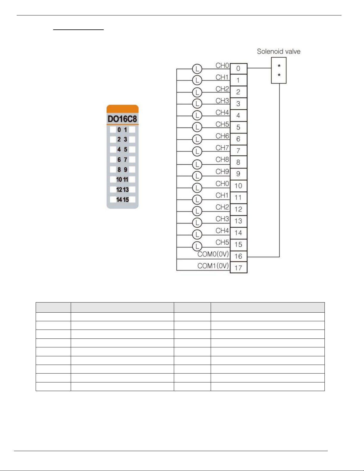
URD-0016CG-8 (DO16C8) - 16 Digital Outputs, (Source)
Page 51
Unitronics
51
1. Wiring Diagram
Pin No.
Signal Description
Pin No.
Signal Description
0
Output 0
1
Output 1
2
Output 2
3
Output 3
4
Output 4
5
Output 5
6
Output 6
7
Output 7
8
Output 8
9
Output 9
10
Output 10
11
Output 11
12
Output 12
13
Output 13
14
Output 14
15
Output 15
16
Common (Field Power 0V)
17
Common (Field Power 0V)
Page 52

4/19
Unitronics
52
2. LED Indicators
LED No.
LED Function / Description
LED Color
0
Output 0
Green
1
Output 1
Green
2
Output 2
Green
3
Output 3
Green
4
Output 4
Green
5
Output 5
Green
6
Output 6
Green
7
Output 7
Green
8
Output 8
Green
9
Output 9
Green
10
Output 10
Green
11
Output 11
Green
12
Output 12
Green
13
Output 13
Green
14
Output 14
Green
15
Output 15
Green
Status
LED
Indication
No Signal
Off
Normal Operation
On Signal
Green
Normal Operation
Page 53

Unitronics
53
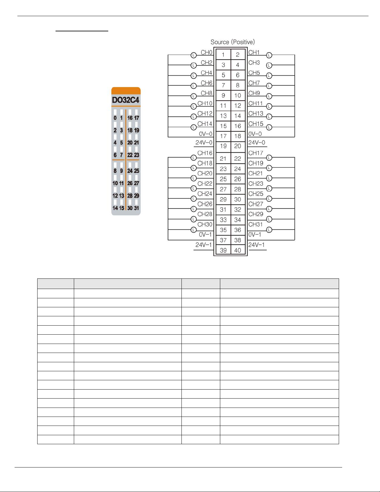
URD-0032CG-4 (DO32C4) - 32 Digital Outputs, (Source)
Items
Specification
Outputs per module
32 Points Source type
Indicators(Logic side )
32 Green Output status
Output Voltage Range
Nominal 24VDC
Min. 15VDC to Max. 32VDC
ON-state voltage drop
Max. 0.3Vdc @ 25 ºC )77°F( / 0.5Vdc@ 60 ºC )140°F(
ON-State Min. Current
Min. 1mA / Channel
OFF-State Leakage current
Max. 5uA
Output Signal Delay
OFF to ON : 0.3ms maximum
ON to OFF : 0.3ms maximum
Output Current Rating
Max. 0.3A per channel /Max. 6.0A per unit
COMMON Type
32 points / 4 Common
Power dissipation
65mA maximum @ 5.0VDC
Isolation
I/O to Logic : Photocoupler Isolation
Field Power : Non-Isolation
Field Power
Supply voltage : 24VDC nominal
Voltage range : 15 to 32VDC
Power dissipation: 30mA @ 32VDC
Wiring
Module connector : HIF3BA-40D-2.54R
Weight
63g
Module Size
12mm x 109mm x 70mm
Operating temperature
-40°C to 70°C (-40°F to 158°F)
Page 54
4/19
Unitronics
54
1. Wiring Diagram
Pin No.
Signal Description
Pin No.
Signal Description
0
Output 0
1
Output 1
2
Output 2
3
Output 3
4
Output 4
5
Output 5
6
Output 6
7
Output 7
8
Output 8
9
Output 9
10
Output 10
11
Output 11
12
Output 12
13
Output 13
14
Output 14
15
Output 15
16
Common (Field Power 0V)
17
Common (Field Power 0V)
18
Common (Field Power 24V)
19
Common (Field Power 24V)
20
Output 16
21
Output 17
22
Output 18
23
Output 19
24
Output 20
25
Output 21
26
Output 22
27
Output 23
28
Output 24
29
Output 25
30
Output 26
31
Output 27
32
Output 28
33
Output 29
Page 55
Unitronics
55
34
Output 30
35
Output 31
36
Common (Field Power 0V)
37
Common (Field Power 0V)
38
Common (Field Power 24V)
39
Common (Field Power 24V)
LED No.
LED Function / Description
LED Color
0
Output 0
Green
1
Output 1
Green
2
Output 2
Green
3
Output 3
Green
4
Output 4
Green
5
Output 5
Green
6
Output 6
Green
7
Output 7
Green
8
Output 8
Green
9
Output 9
Green
10
Output 10
Green
11
Output 11
Green
12
Output 12
Green
13
Output 13
Green
...
...
...
31
Output 31
Green
Status
LED
Indication
No Signal
Off
No Output Signal
On Signal
Green
Normal Operation
2. LED Indicators
Page 56
4/19
Unitronics
56
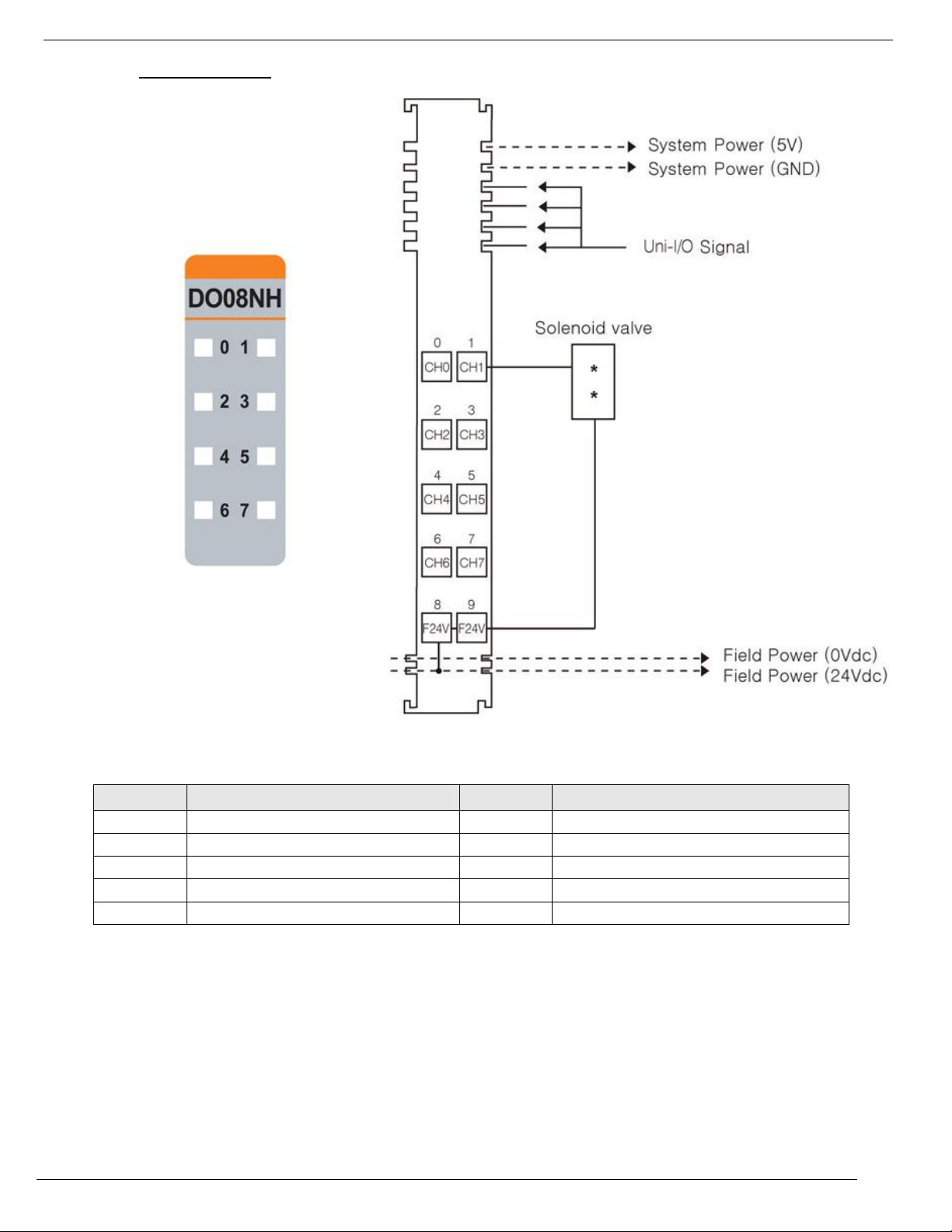
URD-0008NH (DO08NH) - 8 Digital Outputs (Sink)
Items
Specification
Outputs per module
8 Points, Sink type
Indicators(Logic side )
8 Green Output status
Output Voltage Range
Nominal 24VDC
Min. 15VDC to Max. 32VDC
ON-state voltage drop
Max. 0.5VDC @ 25 ºC (77°F)
ON-State Min. Current
1mA per output
OFF-State Leakage current
Max. 25uA
Output Signal Delay
OFF to ON : 0.3ms maximum
ON to OFF : 0.3ms maximum
Output Current Rating
Max. 0.5A per output / Max. 4A per unit
Protection
Over Current limit: Min. 3.5A@ 25 ºC (77°F) per each outputs
Thermal Shutdown : Min 3A@ 25 ºC (77°F) per each outputs
Short circuit protection
COMMON Type
8 points / Internal 2Com
Power dissipation
45mA maximum @ 5.0VDC
Isolation
I/O to Logic : Isolation
Field power : Non-isolation
Field Power
Supply voltage : 24VDC nominal
Voltage range : 15 to 32VDC
Power dissipation: 5mA @32.0VDC
Wiring
I/O Cable Max. 2.0 (AWG 14)
Weight
39g
Module Size
12mm x 99mm x 70mm
Operating temperature
-40°C to 70°C (-40°F to 158°F)
Page 57
Unitronics
57
1. Wiring Diagram
Pin No.
Signal Description
Pin No.
Signal Description
0
Output 0
1
Output 1
2
Output 2
3
Output 3
4
Output 4
5
Output 5
6
Output 6
7
Output 7
8
Common (Field Power 24V)
9
Common (Field Power 24V)
Page 58

4/19
Unitronics
58
2. LED Indicators
LED No.
LED Function / Description
LED Color
0
Output 0
Green
1
Output 1
Green
2
Output 2
Green
3
Output 3
Green
4
Output 4
Green
5
Output 5
Green
6
Output 6
Green
7
Output 7
Green
Status
LED
Indication
No Signal
Off
Normal Operation
On Signal
Green
Normal Operation
Page 59

Unitronics
59
Items
Specification
Outputs per module
8 Points, Sink type
Indicators(Logic side )
8 Green Output status
Output Voltage Range
Nominal 24VDC
Min. 11VDC to Max. 28.8VDC
ON-state voltage drop
Max. 1Vdc @ 25 ºC (77°F)
ON-State Min. Current
1mA per channel
OFF-State Leakage current
Max. 150uA
Output Signal Delay
OFF to ON : 0.3ms maximum
ON to OFF : 0.3ms maximum
Output Current Rating
Max. 2A per channel
Operating Temperature
-40°C to 50°C (-40°F to 122°F): Max. 10A per unit
50°C to 60°C (122°F to 140°F): Max. 7A per unit
60°C to 70°C (140°F to 158°F): Max. 4.8A per unit
COMMON Type
8 points / Internal 2Com
Power dissipation
50mA maximum @ 5.0VDC
Isolation
I/O to Logic : Isolation
Field power : Non-isolation
Field Power
Supply voltage : 24VDC nominal
Voltage range : 15 to 32VDC
Power dissipation: 30mA @32.0VDC
Wiring
I/O Cable Max. 2.0 (AWG 14)
Weight
70g
Module Size
12mm x 99mm x 70mm
Operating temperature
-40°C to 70°C (-40°F to 158°F)
URD-0008NI (DO08NI) - 8 Digital Outputs, (Sink)
Page 60

4/19
Unitronics
60
1. Wiring Diagram
Pin No.
Signal Description
Pin No.
Signal Description
0
Output 0
1
Output 1
2
Output 2
3
Output 3
4
Output 4
5
Output 5
6
Output 6
7
Output 7
8
Common (Field Power 24V)
9
Common (Field Power 24V)
Page 61

Unitronics
61
2. LED Indicators
LED No.
LED Function / Description
LED Color
0
Output 0
Green
1
Output 1
Green
2
Output 2
Green
3
Output 3
Green
4
Output 4
Green
5
Output 5
Green
6
Output 6
Green
Status
LED
Indication
No Signal
Off
Normal Operation
On Signal
Green
Normal Operation
Page 62

4/19
Unitronics
62
URD-0016NG-8 (DO16N8) - 16 Digital Outputs, (Sink)
Items
Specification
Outputs per module
16 Points Sink type
Indicators
16 Green output state
Output Voltage Range
Nominal 24VDC
Min. 15VDC to Max. 32VDC
ON-state voltage drop
Max. 0.3Vdc @ 25 ºC (77°F) / 0.5Vdc@ 70 ºC (158°F)
ON-State Min. Current
1mA per channel
OFF-State Leakage current
Max. 20uA
Output Signal Delay
OFF to ON : 0.3ms maximum
ON to OFF : 0.3ms maximum
Output Current Rating
Max. 0.3A per channel / Max. 4.8A per unit
COMMON Type
16 points / 2COM
Power dissipation
50mA maximum @ 5.0VDC
Isolation
I/O to Logic : Photocoupler isolation
Field Power
Supply voltage : 24VDC nominal
Voltage range : 15 to 32VDC
Power dissipation: 30mA @32.0VDC
Wiring
I/O Cable Max. 0.75 (AWG 18)
Weight
63g
Module Size
12mm x 109mm x 70mm
Operating temperature
-40°C to 70°C (-40°F to 158°F)
Page 63

Unitronics
63
1. Wiring Diagram
Pin No.
Signal Description
Pin No.
Signal Description
0
Output 0
1
Output 1
2
Output 2
3
Output 3
4
Output 4
5
Output 5
6
Output 6
7
Output 7
8
Output 8
9
Output 9
10
Output 10
11
Output 11
12
Output 12
13
Output 13
14
Output 14
15
Output 15
16
Common (Field Power 24V)
17
Common (Field Power 24V)
Page 64
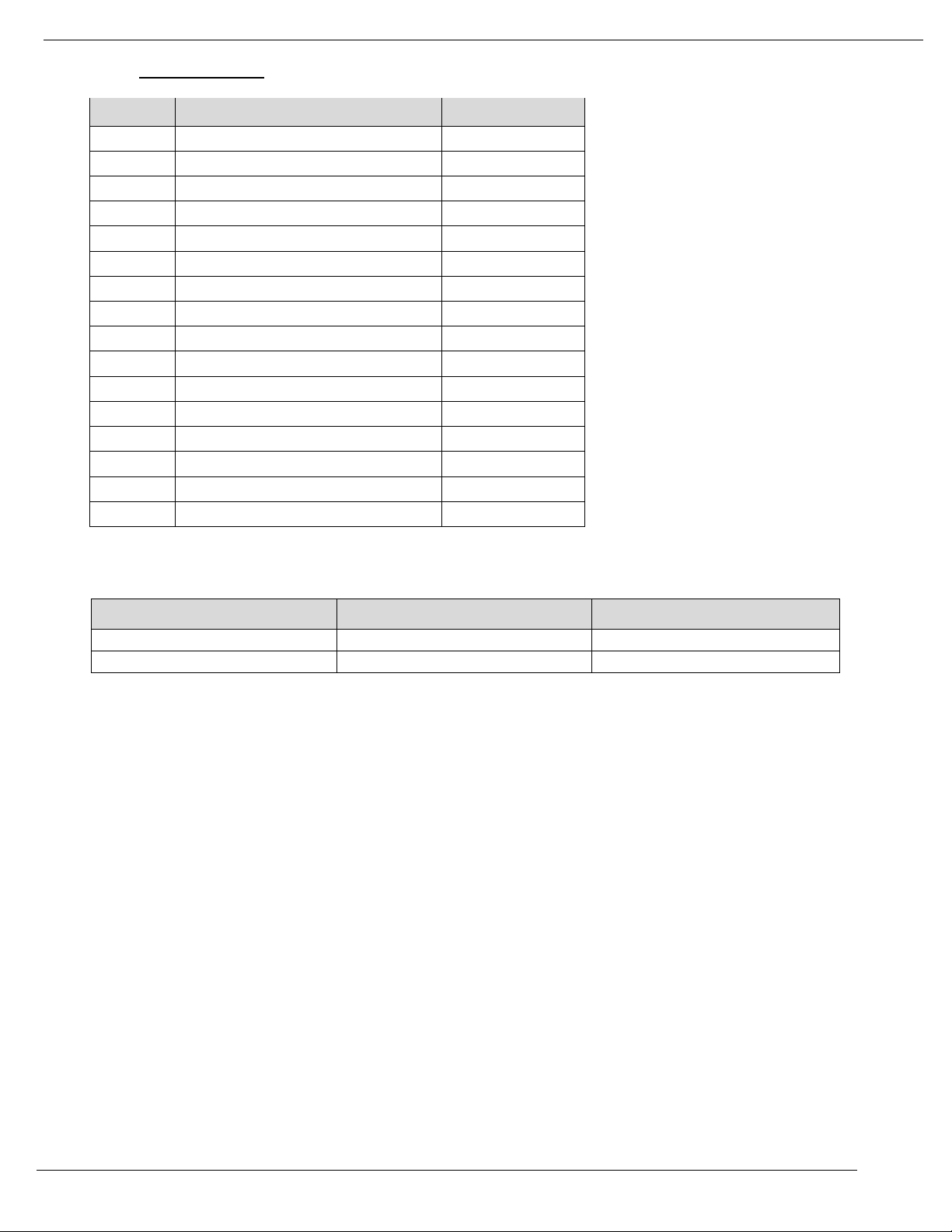
4/19
Unitronics
64
2. LED Indicators
LED No.
LED Function / Description
LED Color
0
Output 0
Green
1
Output 1
Green
2
Output 2
Green
3
Output 3
Green
4
Output 4
Green
5
Output 5
Green
6
Output 6
Green
7
Output 7
Green
8
Output 8
Green
9
Output 9
Green
10
Output 10
Green
11
Output 11
Green
12
Output 12
Green
13
Output 13
Green
14
Output 14
Green
15
Output 15
Green
Status
LED
Indication
No Signal
Off
Normal Operation
On Signal
Green
Normal Operation
Page 65

Unitronics
65
URD-0032NG-4 (DO32N4) - 32 Digital Outputs, (Sink)
Items
Specification
Outputs per module
32 Points Sink Type
Indicators
32 Green Output Status LEDs
Output Voltage Range
24VDC
Min. 15VDC to Max. 32VDC
ON-state voltage drop
Max. 0.3Vdc @ 25 ºC (77°F) / 0.5Vdc @ 60 ºC (140°F)
ON-State Min. Current
Min. 1mA / Channel
OFF-State Leakage current
Max. 25uA
Output Signal Delay
OFF to ON : 0.3ms maximum
ON to OFF : 0.3ms maximum
0ch~15ch < 16ch~31ch : max. 20us
Output Current Rating
Max. 0.3A per channel / Max. 6.0A per unit
COMMON Type
32 points / 4 Common
Power dissipation
65mA maximum @ 5.0VDC
Isolation
I/O to Logic : Photocoupler Isolation
Field Power : Non-Isolation
Field Power
Supply voltage : 24VDC nominal
Voltage range : 15 to 32VDC
Power dissipation: 10mA @32.0VDC
Wiring
Module connector : HIF3BA-40D-2.54R
Weight
59g
Module Size
12mm x 109mm x 70mm
Operating temperature
-40°C to 70°C (-40°F to 158°F)
Page 66
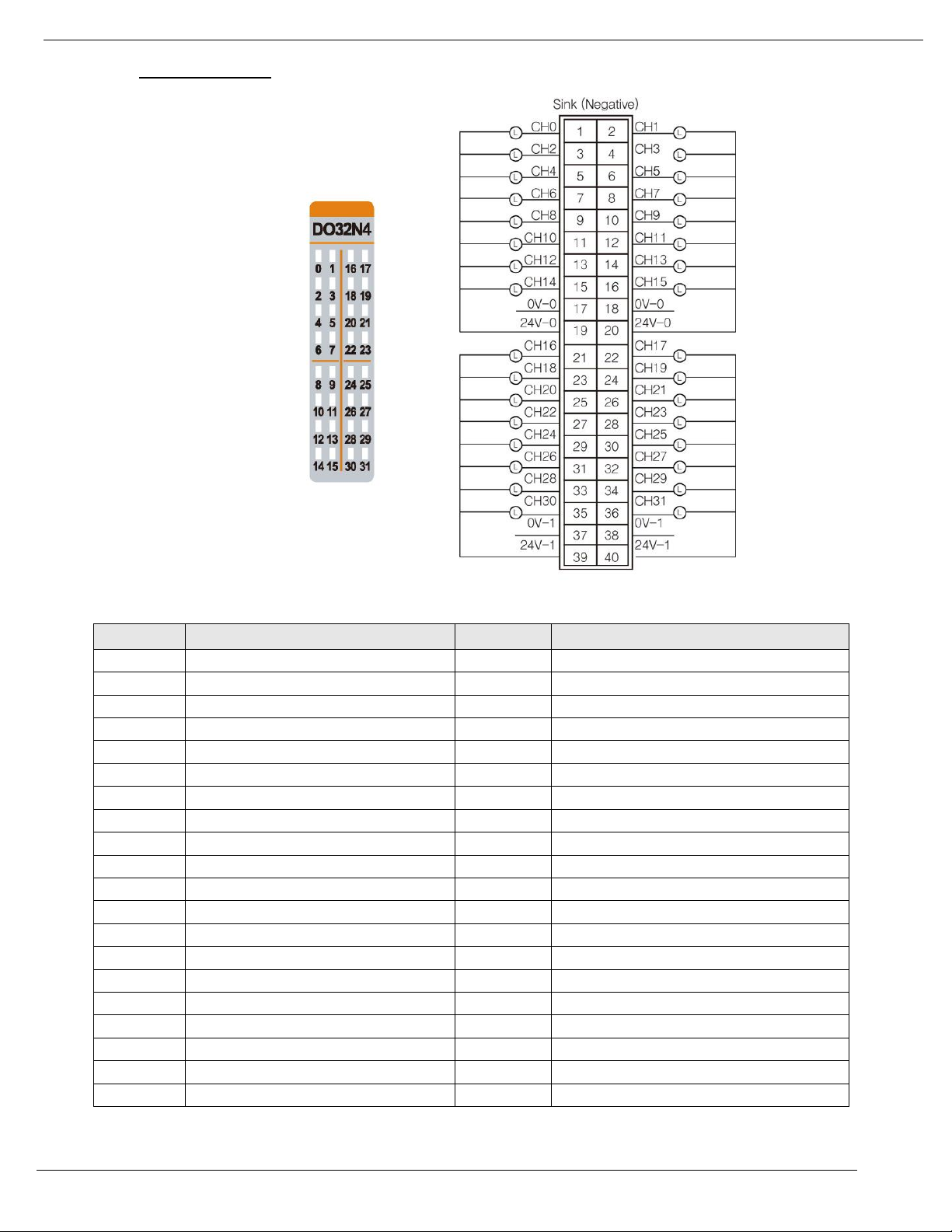
4/19
Unitronics
66
1. Wiring Diagram
Pin No.
Signal Description
Pin No.
Signal Description
0
Output 0
1
Output 1
2
Output 2
3
Output 3
4
Output 4
5
Output 5
6
Output 6
7
Output 7
8
Output 8
9
Output 9
10
Output 10
11
Output 11
12
Output 12
13
Output 13
14
Output 14
15
Output 15
16
Common (Field Power 0V)
17
Common (Field Power 0V)
18
Common (Field Power 24V)
19
Common (Field Power 24V)
20
Output 16
21
Output 17
22
Output 18
23
Output 19
24
Output 20
25
Output 21
26
Output 22
27
Output 23
28
Output 24
29
Output 25
30
Output 26
31
Output 27
32
Output 28
33
Output 29
34
Output 30
35
Output 31
36
Common (Field Power 0V)
37
Common (Field Power 0V)
38
Common (Field Power 24V)
39
Common (Field Power 24V)
Page 67
Unitronics
67
LED No.
LED Function / Description
LED Color
0
Output 0
Green
1
Output 1
Green
2
Output 2
Green
3
Output 3
Green
4
Output 4
Green
5
Output 5
Green
6
Output 6
Green
7
Output 7
Green
8
Output 8
Green
9
Output 9
Green
10
Output 10
Green
11
Output 11
Green
12
Output 12
Green
13
Output 13
Green
Status
LED
Indication
No Signal
Off
No Output Signal
On Signal
Green
Normal Operation
2. LED Indicators
Page 68
4/19
Unitronics
68
URD-0004RH (DO04RH) - 4 Relay Outputs
Items
Specification
Output per module
4 Points, Bi-directional
Indicators (Logic side)
4 Green Output state
Relay Type
Form A, Single Pole Single Throw (SPST)
Output Voltage Range
( Load Dependent )
0~32VDC @ 2.0A resistive
48VDC @ 0.8A resistive
110VDC @ 0.5A resistive
Max. 240VAC @ 2.0A resistive
Output Current Rating
( At rated power )
2.0A @ 0~32VDC
0.8A @ 48VDC
0.5A @ 110VDC
2.0A @ 240VAC
-40 ºC to 70 ºC (-40°F to 158°F) (2A Load 2ch)
-40 ºC to 60 ºC (-40°F to 140°F) (2A Load 4ch)
Output Delay Time
(resistive load)
OFF to ON: Max. 5ms @ 24VDC
ON to OFF: Max. 8ms @ 24VDC
OFF to ON: Max. 5ms @ 220VAC
ON to OFF: Max. 15ms @ 220VAC
Expected Contact Life
20M Cycles (Resistive)
Frequency Range (VAC)
47Hz ~ 63Hz
Max. On-State Voltage Drop*
0.5V @ 2.0A, Resistive Load, 24VDC
Commons Type
4Points / 2COM (Single Common)
Power dissipation
35mA @ 5.0VDC
Isolation
I/O to Logic : Isolation
Field Power : Non-isolation
Field Power
Supply voltage : 24VDC nominal
Voltage range : 22 to 26VDC
Power dissipation: 30mA @ 24VDC
(AC Power Not used)
Wiring
I/O Cable Max. (AWG 14)
Weight
58g
Module Size
12mm x 99mm x 70mm
Operating temperature
-40°C to 70°C (-40°F to 158°F)
Page 69
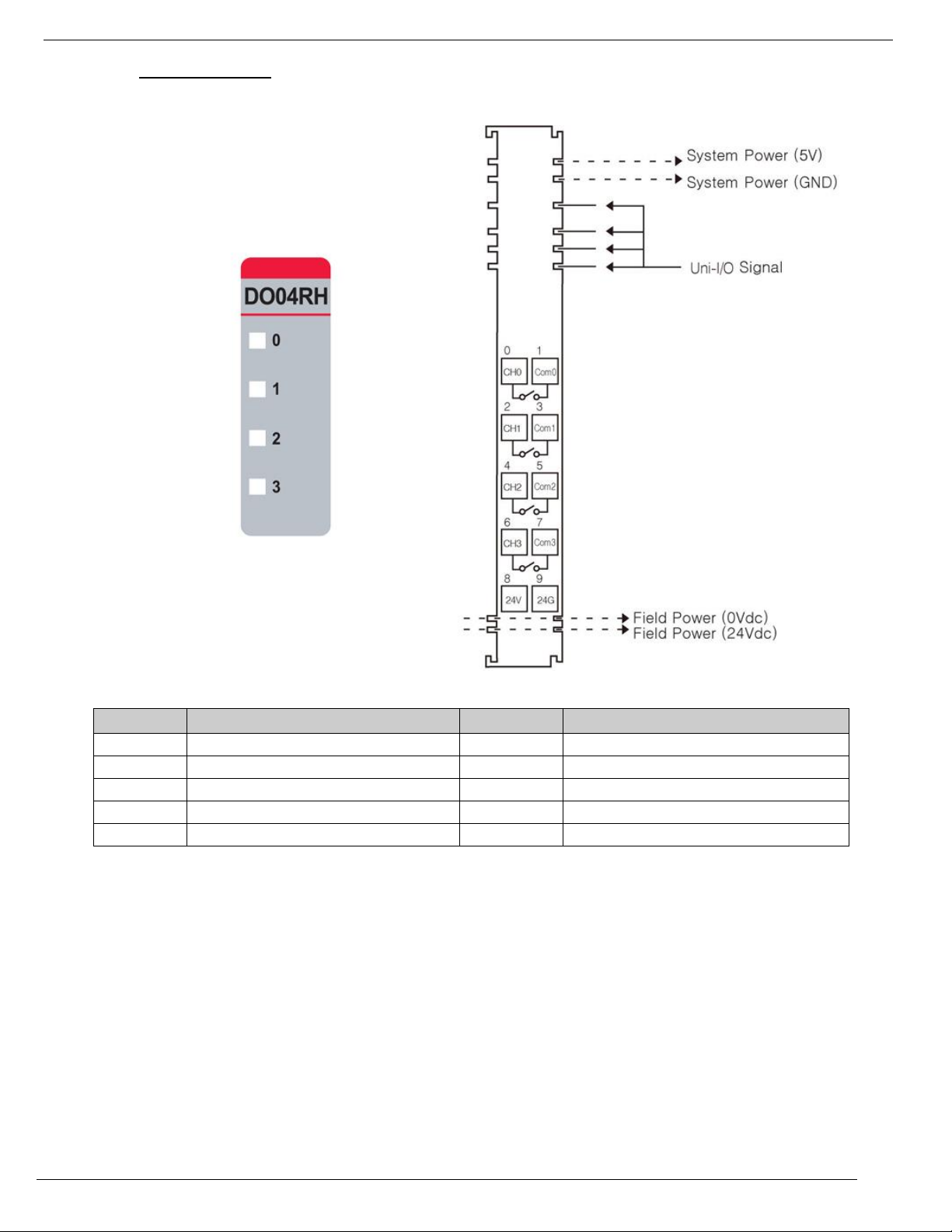
Unitronics
69
Pin No.
Signal Description
Pin No.
Signal Description
0
Output 0
1
COM 0
2
Output 1
3
COM 1
4
Output 2
5
COM 2
6
Output 3
7
COM 3
8
Field Power 24V
9
Field Power 0V
1. Wiring Diagram
Page 70
4/19
Unitronics
70
LED No.
LED Function / Description
LED Color
0
Output 0
Green
1
Output 1
Green
2
Output 2
Green
3
Output 3
Green
Status
LED
Indication
No Signal
Off
Normal Operation
On Signal
Green
Normal Operation
2. LED Indicators
Page 71
Unitronics
71
Items
Specification
Output per module
4 Points, Bi-directional
Indicators (Logic side)
4 Green Output state
Relay Type
MOS Relay (Solid State Relay)
Output Voltage Range
( Load Dependent )
Max. 240VAC @ 0.5A resistive
Max. 240VDC @ 0.5A resistive
Output Delay Time
(resistive load)
Max. AC/DC : 240V
OFF to ON : Max. 0.6ms
ON to OFF : Max. 3ms
Output Current Rating
Max. 0.5A per channel
Frequency Range (VAC)
47Hz ~ 63Hz
Commons Type
4Points / 2COM (Single Common)
Power dissipation
80mA @ 5.0VDC
Isolation
I/O to Logic : Isolation
Field Power : Non-isolation
Field Power
Supply Voltage : 24VDC
Voltage Range : 15 ~ 32VDC
(AC Power Not Used)
Wiring
I/O Cable Max. 2.0 (AWG 14)
Weight
58g
Module Size
12mm x 99mm x 70mm
Operating temperature
-40°C to 70°C (-40°F to 158°F)
URD-0004SK (DO04SK) - 4 Solid State Relay
Page 72
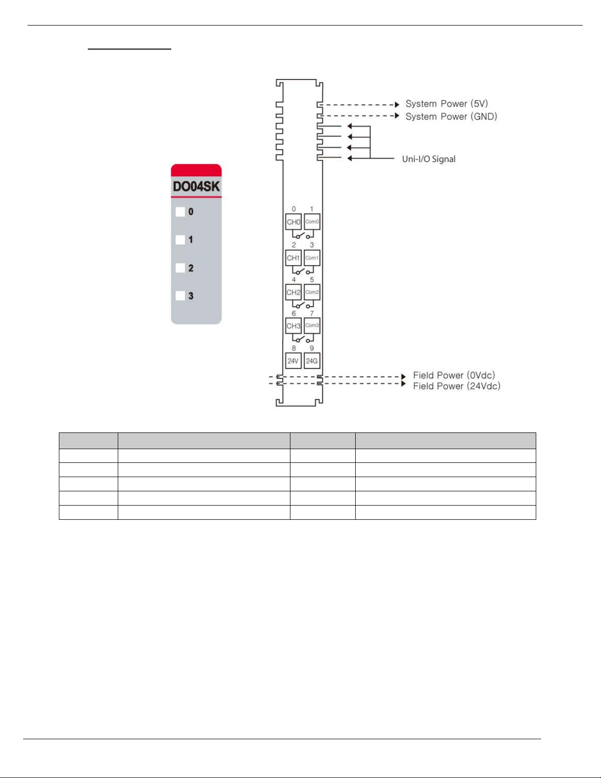
4/19
Unitronics
72
Pin No.
Signal Description
Pin No.
Signal Description
0
Output 0
1
COM 0
2
Output 1
3
COM 1
4
Output 2
5
COM 2
6
Output 3
7
COM 3
8
Field Power 24V
9
Field Power 0V
1. Wiring Diagram
Page 73

Unitronics
73
LED No.
LED Function / Description
LED Color
0
Output 0
Green
1
Output 1
Green
2
Output 2
Green
3
Output 3
Green
Status
LED
Indication
No Signal
Off
No Output Signal
On Signal
Green
Normal Operation
2. LED Indicators
Page 74

4/19
Unitronics
74
URD-0004SM (DO04SM) - 4 Solid State Relay
Items
Specification
Output per module
4 Points, Bi-directional
Indicators (Logic side)
4 Green Output state
Relay Type
MOS Relay (Solid State Relay)
Output Voltage Range
( Load Dependent )
Max. 110VAC @ 1A resistive
Max. 110VDC @ 1A resistive
Output Delay Time
(resistive load)
AC:
OFF to ON : Max. 1ms
ON to OFF : Max. 3ms
DC:
OFF to ON : Max. 1.5ms
ON to OFF : Max. 3ms
Output Current Rating
Max. 1A per channel
60 ºC (140°F) : 0.8A per channel
50 ºC (122°F) : 1A per channel
Frequency Range (VAC)
47Hz ~ 63Hz
Commons Type
4Points / 2COM (Single Common)
Power dissipation
80mA @ 5.0VDC
Isolation
I/O to Logic : Isolation
Field Power : Non-isolation
Field Power
Supply Voltage : 24VDC
Voltage Range : 15 ~ 32VDC
(AC Power Not Used)
Wiring
I/O Cable Max. 2.0 (AWG 14)
Weight
58g
Module Size
12mm x 99mm x 70mm
Operating temperature
-40°C to 60°C (-40°F to 140°F)
Page 75

Unitronics
75
Pin No.
Signal Description
Pin No.
Signal Description
0
Output 0
1
COM 0
2
Output 1
3
COM 1
4
Output 2
5
COM 2
6
Output 3
7
COM 3
8
Field Power 24V
9
Field Power 0V
1. Wiring Diagram
Page 76

4/19
Unitronics
76
LED No.
LED Function / Description
LED Color
0
Output 0
Green
1
Output 1
Green
2
Output 2
Green
3
Output 3
Green
Status
LED
Indication
Not Signal
Off
No Output Signal
On Signal
Green
Normal Operation
2. LED Indicators
Page 77

Unitronics
77
URD-0004SN (DO04SN) - 4 Solid State Relay
Items
Specification
Output per module
4 Points, Bi-directional
Indicators (Logic side)
4 Green Output state
Relay Type
MOS Relay (Solid State Relay)
Output Voltage Range
( Load Dependent )
Max. 24VAC @ 2A resistive
Max. 24VDC @ 2A resistive
Output Delay Time
(resistive load)
AC:
OFF to ON : Max. 1ms
ON to OFF : Max. 3ms
DC:
OFF to ON : Max. 1 ms
ON to OFF : Max. 3.5ms
Output Current Rating
Max. 2A per channel
-40°C to 70°C (-40°F to 158°F) : Max. 7A per unit
-40°C to 50°C (-40°F to 122°F) : Max. 8A per unit
Frequency Range (VAC)
47Hz ~ 63Hz
Commons Type
4Points / 2COM (Single Common)
Power dissipation
80mA @ 5.0VDC
Isolation
I/O to Logic : Isolation
Field Power : Non-isolation
Field Power
Supply Voltage : 24VDC
Voltage Range : 15 ~ 32VDC
(AC Power Not Used)
Wiring
I/O Cable Max. 2.0 (AWG 14)
Weight
58g
Module Size
12mm x 99mm x 70mm
Operating temperature
-40°C to 70°C (-40°F to 158°F)
Page 78

4/19
Unitronics
78
Pin No.
Signal Description
Pin No.
Signal Description
0
Output 0
1
COM 0
2
Output 1
3
COM 1
4
Output 2
5
COM 2
6
Output 3
7
COM 3
8
Field Power 24V
9
Field Power 0V
1. Wiring Diagram
Page 79

Unitronics
79
LED No.
LED Function / Description
LED Color
0
Output 0
Green
1
Output 1
Green
2
Output 2
Green
3
Output 3
Green
Status
LED
Indication
No Signal
Off
No Output Signal
On Signal
Green
Normal Operation
2. LED Indicators
Page 80
4/19
Unitronics
80
URA-0400O (AI04O) - 4 Current Inputs
Items
Specification
Inputs per module
4 inputs single ended, non-isolated between inputs
Indicators(Logic side )
4 Green Input status
Resolution in Ranges
12 bits : 4.88uA/Bit(0~20mA), 3.91uA/Bit(4~20mA)
Input Range
0~20mA, 4~20mA
Data Format
16bits Integer (2' compliment)
Module Error
±0.1% Full Scale @ 25 ºC (77°F) ambient
±0.3% Full Scale @ -40 ºC, 70 ºC (-40°F to 158°F)
Input Impedance
121.5Ω
Diagnostic
Diagnostic Field Power Off : LED Blinking
Field Power On : LED Off < 0.5% (Maximum Input Value)
Field Power On : LED On > 0.5% (Maximum Input Value)
Maximum Range Over : LED Off > 21mA
Minimum Range Over : LED Off < 3mA ( 4 ~ 20mA)
Conversion Time
800usec / All input
Field calibration
Not Required
Common Type
4 Common, Field Power 0V is Common(AGND)
Power dissipation
Max. 25mA @ 5.0VDC
Isolation
I/O to Logic : Isolation
Field power : Non-Isolation
Field Power
Supply Voltage : 24VDC nominal
Voltage Range : 18 to 32VDC
Power Dissipation : Max. 25mA@24VDC
Wiring
I/O Cable Max. 2.0 (AWG 14)
Weight
58g
Module Size
12mm x 99mm x 70mm
Operating temperature
-40°C to 70°C (-40°F to 158°F)
Page 81
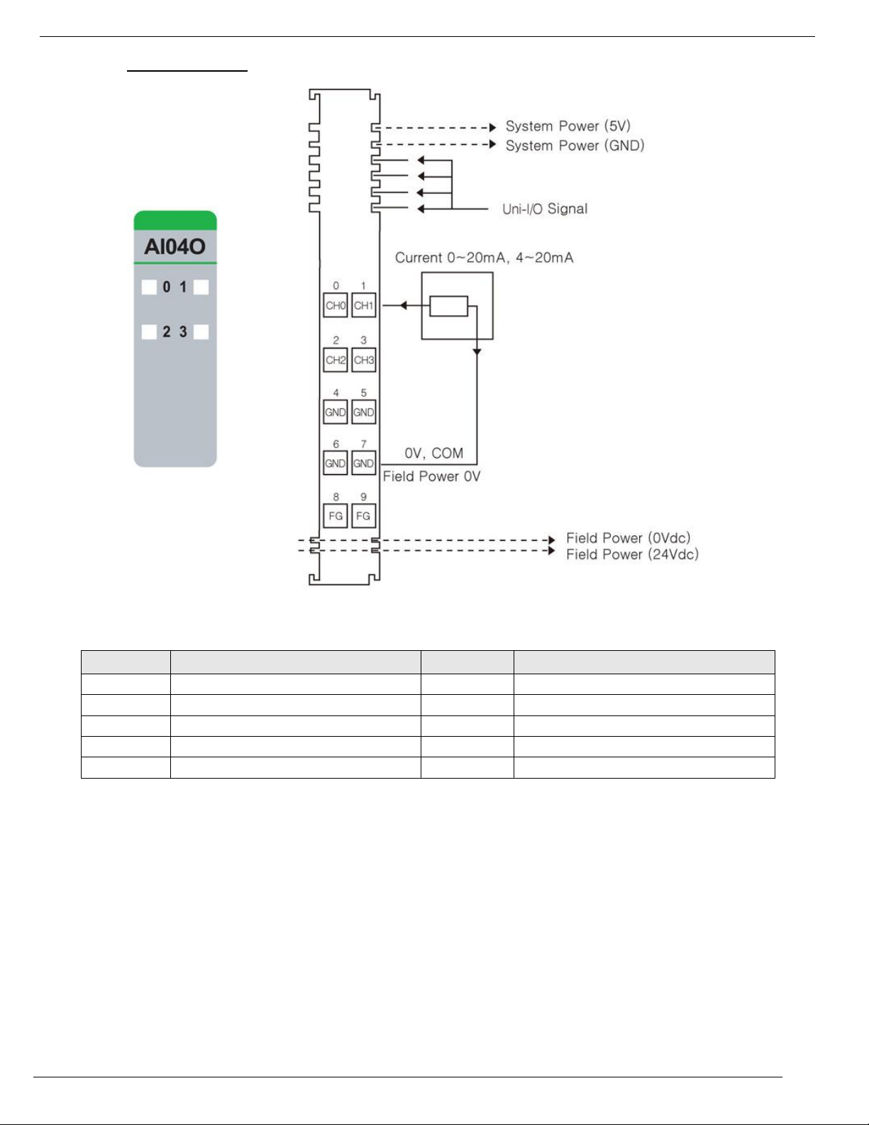
Unitronics
81
1. Wiring Diagram
Pin No.
Signal Description
Pin No.
Signal Description
0
Input 0
1
Input 1
2
Input 2
3
Input 3
4
Input Common(AGND)
5
Input Common(AGND)
6
Input Common(AGND)
7
Input Common(AGND)
8
Field Ground
9
Field Ground
Page 82

4/19
Unitronics
82
2. LED Indicators
LED No.
LED Function / Description
LED Color
0
Input 0
Green
1
Input 1
Green
2
Input 2
Green
3
Input 3
Green
Status
LED
Indication
Normal Operation
[LED Off < 0.5% (Maximum Input Value)] - Input OFF
[LED On > 0.5% (Maximum Input Value)] - Input Green
Normal Operation
Overrun/Underrun
[LED Off > 21mA (Maximum Range Over] – Input OFF
[LED Off < 3mA (Minimum Range Over , 4 ~ 20mA)] – Input
OFF
Over range Check
Field Power Error
All Input Repeat the Green and OFF
Field Power is
unconnected
Page 83

Unitronics
83
Items
Specification
Inputs per module
8 Inputs single ended, non-isolated between inputs
Indicators(Logic side )
8 Green Input status
Resolution in Ranges
12 bits : 4.88uA/Bit(0~20mA), 3.91uA/Bit(4~20mA)
Input Range
0~20mA, 4~20mA
Data Format
16bits Integer (2' compliment)
Module Error
±0.1% Full Scale @ 25 ºC (77°F) ambient
±0.3% Full Scale @ -40 ºC, 70 ºC (-40°F, 158°F)
Input Impedance
121.5Ω
Diagnostic
Diagnostic Field Power Off : LED Blinking
Field Power On : LED Off < 0.5% (Maximum Input Value)
Field Power On : LED On > 0.5% (Maximum Input Value)
Maximum Range Over : LED Off > 21mA
Minimum Range Over : LED Off < 3mA ( 4 ~ 20mA)
Conversion Time
≤ 1msec / All channel (≤ 0.125ms per channel)
Field calibration
Not Required
Common Type
2 Common, Field Power 0V is Common(AGND)
Power dissipation
Max. 30mA @ 5.0VDC
Isolation
I/O to Logic : Isolation
Field power : Non-Isolation
Field Power
Supply Voltage : 24VDC nominal
Voltage Range : 18 to 32VDC
Power Dissipation : Max. 30mA@24VDC
Wiring
I/O Cable Max. 2.0 (AWG 14)
Weight
58g
Module Size
12mm x 99mm x 70mm
Operating temperature
-40°C to 70°C (-40°F to 158°F)
URA-0800O (AI08O) - 8 Current Inputs
Page 84
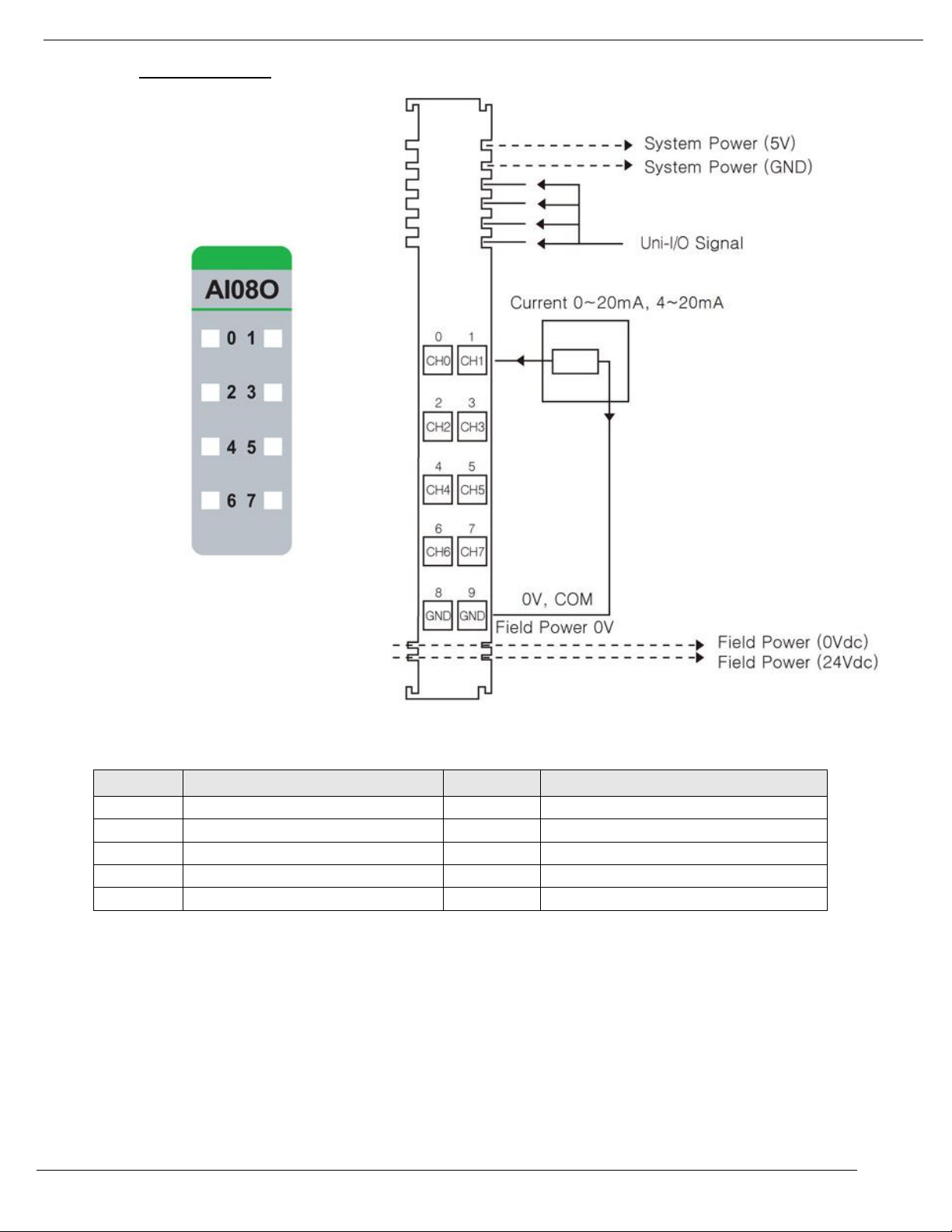
4/19
Unitronics
84
1. Wiring Diagram
Pin No.
Signal Description
Pin No.
Signal Description
0
Input 0
1
Input 1
2
Input 2
3
Input 3
4
Input 4
5
Input 5
6
Input 6
7
Input 7
8
Input Common(AGND)
9
Input Common(AGND)
Page 85
Unitronics
85
LED No.
LED Function / Description
LED Color
0
Input 0
Green
1
Input 1
Green
2
Input 2
Green
3
Input 3
Green
4
Input 4
Green
5
Input 5
Green
6
Input 6
Green
7
Input 7
Green
Status
LED
Indication
Normal Operation
[LED Off < 0.5% (Maximum Input Value)] - Input OFF
[LED On > 0.5% (Maximum Input Value)] - Input Green
Normal Operation
Overrun/Underrun
[LED Off > 21mA (Maximum Range Over] – Input OFF
[LED Off < 3mA (Minimum Range Over , 4 ~ 20mA)] – Input
OFF
Over range Check
Field Power Error
All Input Repeat the Green and OFF
Field Power is
unconnected
2. LED Indicators
Page 86
4/19
Unitronics
86
URA-1600O-8 (AI16O8) - 16 Analog Current Inputs 12bit
Items
Specification
Inputs per module
16 Channels single ended, non-isolated between channels
Indicators(Logic side )
1 Green status LED
Resolution in Ranges
12 bits : 4.88uA/Bit(0~20mA), 3.91uA/Bit(4~20mA)
Input Range
0~20mA, 4~20mA
Data Format
16bits Integer (2' compliment)
Module Error
±0.1% Full Scale @ 25 ºC (77°F) ambient
±0.3% Full Scale @ -40 ºC, 60 ºC (-40°F , 140°F)
Input Impedance
121.5Ω
Conversion Time
Max. 3.2msec (All channel)
Field calibration
Not Required
Common Type
2 Common, Field Power 0V is Common(AGND)
Power dissipation
Max. 200mA @ 5.0VDC
Isolation
I/O to Logic : Photocoupler Isolation
Field power : Not Connected
Field Power
Not used Field power bypass to next expansion module
Wiring
I/O Cable Max. 1.0 (AWG 18)
Weight
63g
Module Size
12mm x 109mm x 70mm
Operating temperature
-40°C to 60°C (-40°F to 140°F)
Page 87
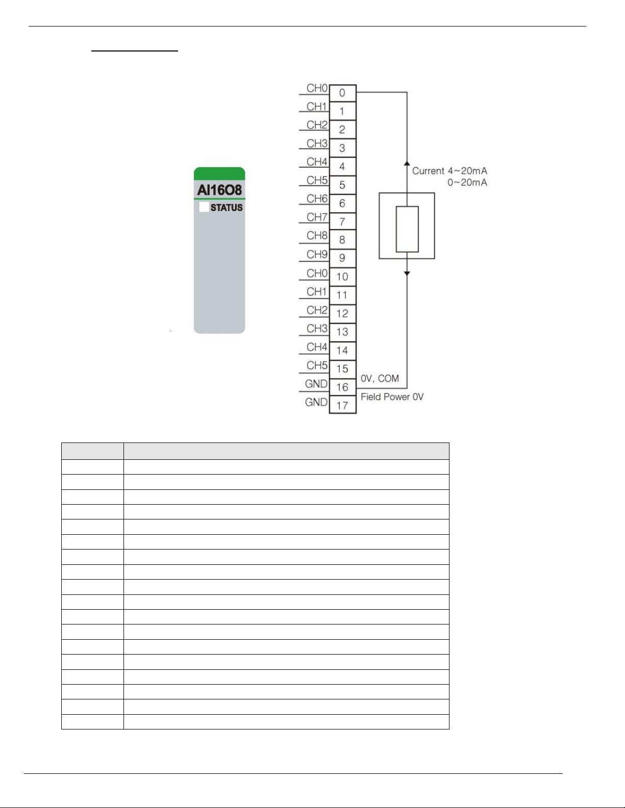
Unitronics
87
1. Wiring Diagram
Pin No.
Signal Description
0
Input 0
1
Input 1
2
Input 2
3
Input 3
4
Input 4
5
Input 5
6
Input 6
7
Input 7
8
Input 8
9
Input 9
10
Input 10
11
Input 11
12
Input 12
13
Input 13
14
Input 14
15
Input 15
16
Input Common(AGND)
17
Input Common(AGND)
Page 88

4/19
Unitronics
88
2. LED Indicators
LED No.
LED Function / Description
LED Color
0
Input 0
Green
Status
LED
Indication
Uni-I/O Status
Off
Disconnection
Green
Connection
Page 89
Unitronics
89
URA-0400P (AI04P) - 4 Analog Voltage Inputs 12bit
Items
Specification
Inputs per module
4 Inputs single ended, non-isolated between inputs
Indicators(Logic side )
4 Green Input status
Resolution in Ranges
12 bits : 2.44mV/Bit(0~10V) , 1.22mV/Bit(0~5V), 0.977mV/Bit(1~5V)
Input Current Range
0~10VDC, 0~5VDC, 1~5VDC
Data Format
16bits Integer (2's complement)
Module Error
±0.1% Full Scale @ 25 ºC (77°F) ambient
±0.3% Full Scale @ -40°C, 70°C (-40°F , 158°F)
Input Impedance
500kΩ
Diagnostic
Diagnostic Field Power Off : LED Blinking
Field Power On : LED Off < 0.5% (Maximum Input Value)
Field Power On : LED On > 0.5% (Maximum Input Value)
Conversion Time
≤350usec / All input
Calibration
Not Required
Common Type
4 Common, Field Power 0V is Common(AGND)
Power dissipation
Max. 25mA @ 5.0VDC
Isolation
I/O to Logic : Isolation
Field power : Non-Isolation
Field Power
Supply Voltage : 24VDC nominal
Voltage Range : 18 to 32VDC
Power Dissipation : Max. 25mA@24VDC
Wiring
I/O Cable Max. 2.0 (AWG 14)
Weight
58g
Module Size
12mm x 99mm x 70mm
Operating temperature
-40°C to 70°C (-40°F to 158°F)
Page 90

4/19
Unitronics
90
1. Wiring Diagram
Pin No.
Signal Description
Pin No.
Signal Description
0
Input 0
1
Input 1
2
Input 2
3
Input 3
4
Input Common(AGND)
5
Input Common(AGND)
6
Input Common(AGND)
7
Input Common(AGND)
8
Field Ground
9
Field Ground
Page 91
Unitronics
91
2. LED Indicators
LED No.
LED Function / Description
LED Color
0
Input 0
Green
1
Input 1
Green
2
Input 2
Green
3
Input 3
Green
Status
LED
Indication
Normal Operation
[LED Off < 0.5% (Maximum Input Value)] - Input OFF
[LED On > 0.5% (Maximum Input Value)] - Input Green
Normal Operation
Field Power Error
All Input Repeat the Green and OFF
Field Power is
unconnected
Page 92

4/19
Unitronics
92
Items
Specification
Inputs per module
8 Inputs single ended, non-isolated between inputs
Indicators(Logic side )
8 Green Input status
Resolution in Ranges
12 bits : 2.44mV/Bit(0~10V) , 1.22mV/Bit(0~5V)
Input Current Range
0~10VDC, 0~5 VDC, 1~5 VDC
Data Format
16bits Integer (2's complement)
Module Error
±0.1% Full Scale @ 25 ºC (77°F) ambient
±0.3% Full Scale @ -40°C, 70°C (-40°F to 158°F)
Input Impedance
500kΩ
Diagnostic
Diagnostic Field Power Off : LED Blinking
Field Power On : LED Off < 0.5% (Maximum Input Value)
Field Power On : LED On > 0.5% (Maximum Input Value)
Conversion Time
≤1msec / All Input (≤ 0.125ms per input)
Calibration
Not Required
Common Type
2 Common, Field Power 0V is Common(AGND)
Power dissipation
Max. 30mA @ 5.0VDC
Isolation
I/O to Logic : Isolation
Field power : Non-Isolation
Field Power
Supply Voltage : 24VDC nominal
Voltage Range : 18 to 32VDC
Power Dissipation : Max. 30mA@24VDC
Wiring
I/O Cable Max. 2.0 (AWG 14)
Weight
58g
Module Size
12mm x 99mm x 70mm
Operating temperature
-40°C to 70°C (-40°F to 158°F)
URA-0800P (AI08P) - 8 Analog Voltage Inputs 12bit
Page 93

Unitronics
93
1. Wiring Diagram
Pin No.
Signal Description
Pin No.
Signal Description
0
Input 0
1
Input 1
2
Input 2
3
Input 3
4
Input 4
5
Input 5
6
Input 6
7
Input 7
8
Input Common(AGND)
9
Input Common(AGND)
Page 94

4/19
Unitronics
94
LED No.
LED Function / Description
LED Color
0
Input 0
Green
1
Input 1
Green
2
Input 2
Green
3
Input 3
Green
4
Input 4
Green
5
Input 5
Green
6
Input 6
Green
7
Input 7
Green
Status
LED
Indication
Normal Operation
[LED Off < 0.5% (Maximum Input Value)] - Input OFF
[LED On > 0.5% (Maximum Input Value)] - Input Green
Normal Operation
Field Power Error
All Input Repeat the Green and OFF
Field Power is
unconnected
2. LED Indicators
Page 95

Unitronics
95
Items
Specification
Inputs per module
16 Channels single ended, non-isolated between channels
Indicators(Logic side )
1 Green status LED
Resolution in Ranges
12 bits : 2.44mV/Bit(0~10V) , 1.22mV/Bit(0~5V), 0.98mV/Bit(1~5V)
Input Current Range
0~10VDC, 0~5VDC, 1~5VDC
Data Format
16bits Integer (2's complement)
Module Error
±0.1% Full Scale @ 25°C (77°F) ambient
±0.3% Full Scale @ -40°C, 60°C (-40°F to 140°F)
Input Impedance
500kΩ
Conversion Time
All Channel<1.3ms
Calibration
Not Required
Common Type
2 Common, Field Power 0V is Common(AGND)
Power dissipation
Max. 210mA @ 5.0Vdc
Isolation
I/O to Logic : Photocoupler Isolation
Field power : Not Connected
Field Power
Not used Field power bypass to next expansion module
Wiring
I/O Cable Max. 1.0 (AWG 18)
Weight
63g
Module Size
12mm x 109mm x 70mm
Operating temperature
-40°C to 60°C (-40°F to 140°F)
URA-1600P-8 (AI16P8) - 16 Analog Voltage Inputs 12bit
Page 96
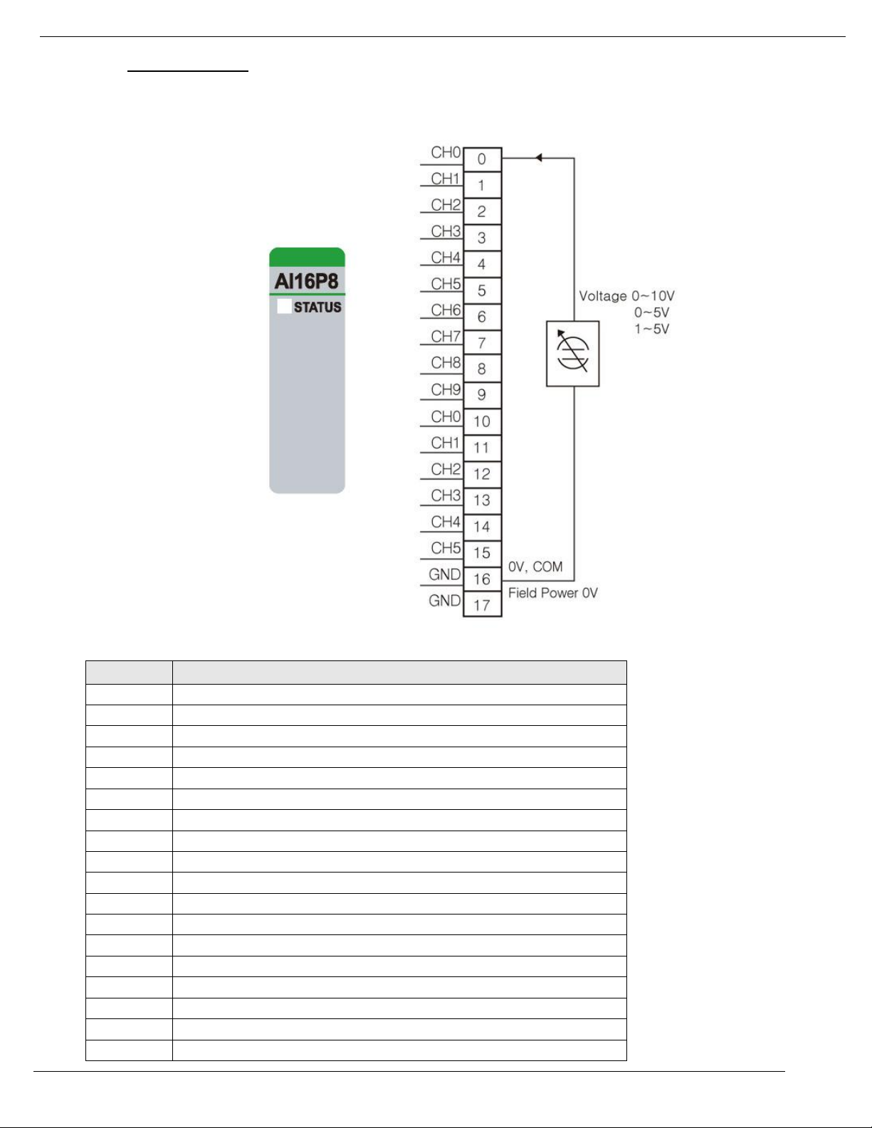
4/19
Unitronics
96
1. Wiring Diagram
Pin No.
Signal Description
0
Input 0
1
Input 1
2
Input 2
3
Input 3
4
Input 4
5
Input 5
6
Input 6
7
Input 7
8
Input 8
9
Input 9
10
Input 10
11
Input 11
12
Input 12
13
Input 13
14
Input 14
15
Input 15
16
Input Common(AGND)
17
Input Common(AGND)
Page 97
Unitronics
97
2. 2. LED Indicators
LED No.
LED Function / Description
LED Color
0
Input 0
Green
Status
LED
Indication
Uni-I/O Status
Off
Disconnection
Green
Connection
Page 98
4/19
Unitronics
98
URA-0400T (AI04T) - 4 Analog Current Inputs 16bit
Items
Specification
Inputs per module
4 Input s single ended, non-isolated between Inputs
Indicators(Logic side )
4 Green Input status
Resolution in Ranges
16 bit (Include Sign)
15 bits : 0.61uA/Bit(0~20mA), 0.49uA/Bit(4~20mA)
Input Range
0~20mA, 4~20mA
Data Format
16bits Integer (2' compliment)
Module Error
±0.1% Full Scale @ 25°C (77°F) ambient
±0.3% Full Scale @ -40°C to 70°C (-40°F to 158°F)
Input Impedance
121.5Ω
Diagnostic
Diagnostic Field Power Off : LED Blinking
Field Power On : LED Off < 0.5% (Maximum Input Value)
Field Power On : LED On > 0.5% (Maximum Input Value)
Minimum Range Over : LED Off < 3mA ( 4 ~ 20mA)
Conversion Time
650usec / All Input
Field calibration
Not Required
Common Type
4 Common, Field Power 0V is Common(AGND)
Power dissipation
Max. 25mA @ 5.0VDC
Isolation
I/O to Logic : Isolation
Field power : Non-Isolation
Field Power
Supply Voltage : 24VDC nominal
Voltage Range : 18 to 32Vdc
Power Dissipation : Max. 20mA@24VDC
Wiring
I/O Cable Max. 2.0 (AWG 14)
Weight
58g
Module Size
12mm x 99mm x 70mm
Operating temperature
-40°C to 70°C (-40°F to 158°F)
Page 99
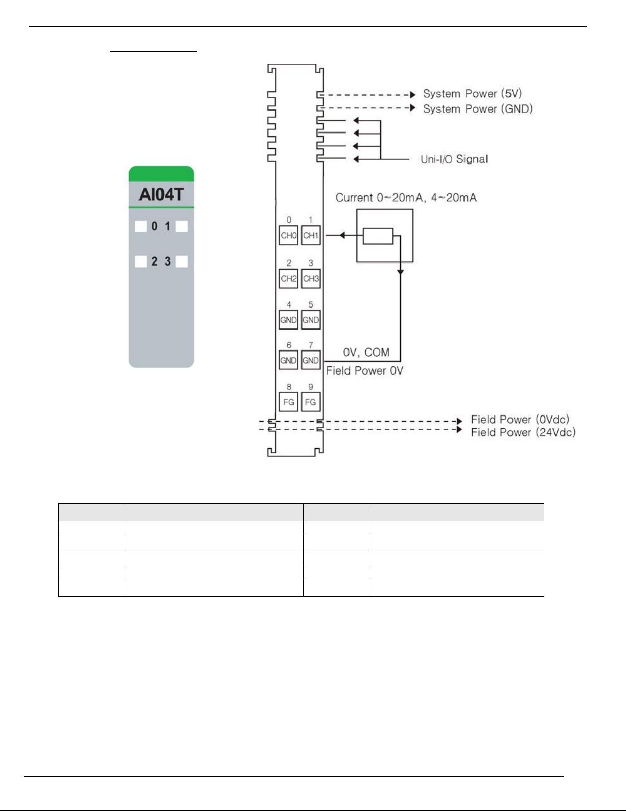
Unitronics
99
1. Wiring Diagram
Pin No.
Signal Description
Pin No.
Signal Description
0
Input 0
1
Input 1
2
Input 2
3
Input 3
4
Input Common(AGND)
5
Input Common(AGND)
6
Input Common(AGND)
7
Input Common(AGND)
8
Field Ground
9
Field Ground
Page 100
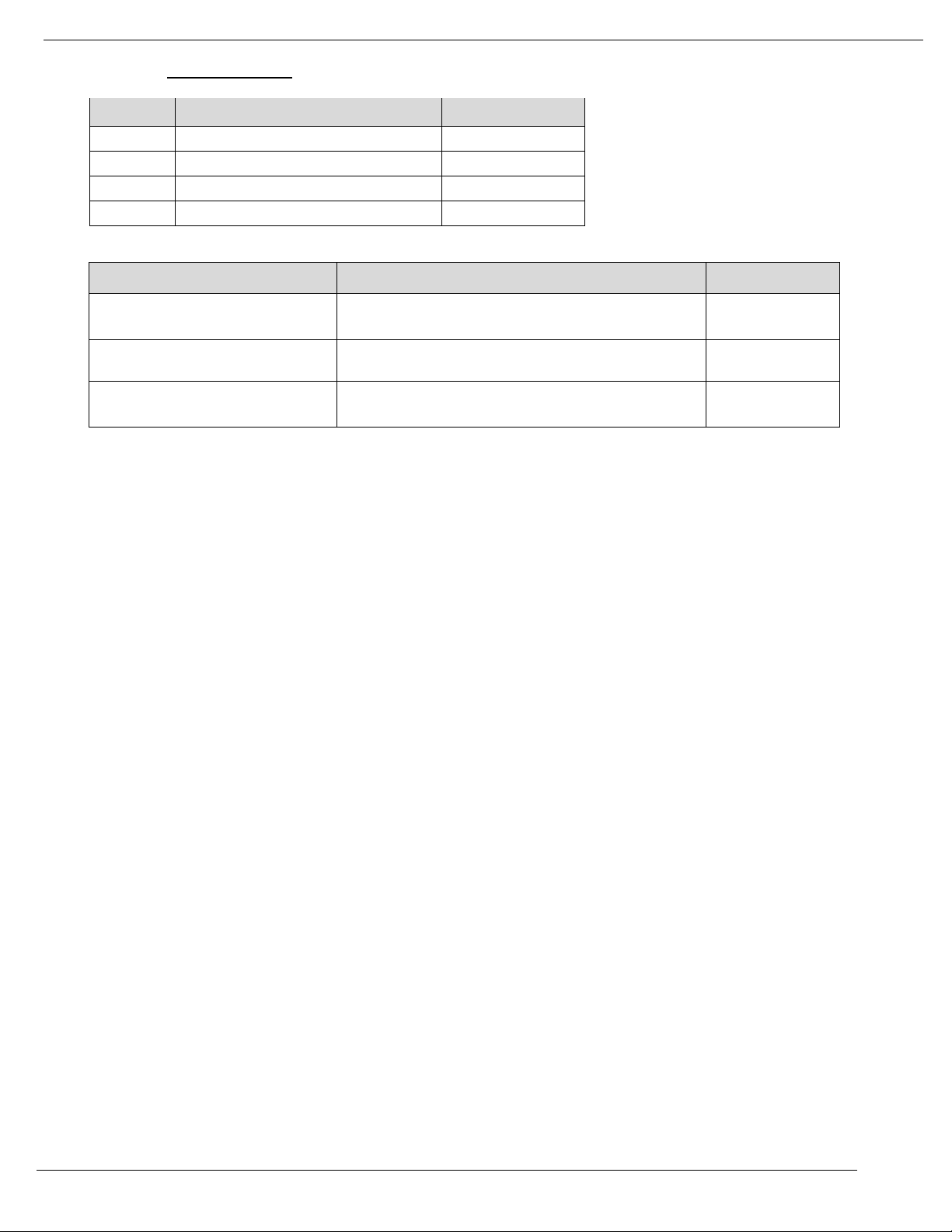
4/19
Unitronics
100
2. LED Indicators
LED No.
LED Function / Description
LED Color
0
Input 0
Green
1
Input 1
Green
2
Input 2
Green
3
Input 3
Green
Status
LED
Indication
Normal Operation
[LED Off < 0.5% (Maximum Input Value)] - Input OFF
[LED On > 0.5% (Maximum Input Value)] - Input Green
Normal Operation
Overrun/Underrun
[LED Off < 3mA (Minimum Range Over , 4 ~ 20mA)] – Input
OFF
Over range Check
Field Power Error
All Input Repeat the Green and OFF
Field Power is
unconnected
 Loading...