

Unitronics UniStream Display, UniStream USL-050-B05, UniStream USL-070-B05 Installation Manual

Unitronics
1
UniStream®
Display
Installation Guide:
USL-050-B05, USL-070-B05
SCAN
to downlo ad
This guide provides basic installation informati on f or UniStream® Display models. Displays
are compatible wit h UniStream
®
PLCs.
Technical spe cifications may be d ownloaded from the Unit ronics website.
General Description
UniStream® Display models comprise re sist i ve color tou ch-screens th a t sup port VN C client,
and are av ailable in d if f erent dimen sion s.
Via VNC, UniStream
®
PLCs can acce ss Displays to show HMI scree ns.
In add ition to H MI screens, Displays support UniApps™, a built-i n system that enab l es
the user to a ccess communication setting s, and manage the device.
Exact fea tur es are detailed in the produ ct specification sheets.
Features
Resistive Color Tou ch-screens
1 Built-in RJ45 Et hern e t port
1 USB host port for firmware updates.
General Features of the UniStream PLC Series
Unitronics’ UniS trea m PLC s are DIN-rail mount ed Programmable L og ic Controllers (PLCs)
with a built-in I/O configuration.
The series is avail ab le in three versions: Pro, Standard, an d Basic.
Note that a model number that includes:
• B10 refers to Pro v ersion (e.g. U SC-B10-T24)
• B5 refe rs to Stand a rd ve rsion ( e.g. U SC-B5-RA28)
• B3 refers to Basic version ( e . g. only for USC-B3-T20)
Page 2 contains a compa rison table detaili ng the features offered by the different models.
Exact fea tur es are detailed in the produ ct specification sheets.
Power
Features
Built-in Trends and Gauges, auto-tuned PID, d ata tables, dat a
sampling, and Recipes
UniApps™: Ac cess & edit data, monito r, troubleshoot & debug and
more
Security: Multi-leve l password protectio n
Alarms: Built-in system, ANSI/ISA standards
COM
Options
Built-in ports: 2 Ethernet , 1 USB host, 1 USB device port
Add-on ports (UAC-CB), a vailable by separate order:
1 CANbus port may be added to all models
RS232/485 p orts : according to model t echnical specifications
COM
Protocols
Fieldb us: CANopen, CAN Layer2, MODBUS, EtherNetIP and more.
Implement any serial RS232/ 4 85, T CP/IP, or CANbus thi rd-party
protocols via Message Com poser
Advanced: SNMP Agent/Trap, e-mail, SM S, modems, GPRS/GSM,
FTP Server/Clie n t , W eb Serve r, SQ L, and M QTT.
Rem o te Access v ia any de vice that supports VNC .

UniStream® Display
Programming
Software
All-in-One UniLogic software for h ardwa re configu rati on,
commu n ica ti on s, PL C and H MI ap plications; f ree d ow nload.
HMI All UniStream® PLCs can display HMI screens on the following devices:
• UniStream Display (USL)
• UniStream Modular HMI p anel (USP)
• UniStream Built-in (on the p anels integral to t he device)
• Any devi ce screen t hat supports VN C
HMI
HMI scre e ns are de signe d in UniL ogic. In addition to the HM I scree ns,
UniStream® PLCs offer built-in HMI features, including:
• UniApps™: Acce ss & edit data, monitor, troubleshoot, debug,
and more
• Security: Multi-level password p rot e cti on
Alarms: Built-in system, ANSI/ISA standard s
USB Action
files
Progra mmers can create files in UniLogic and sav e them to a U SB mass
storage devi ce, such as a f l a sh drive. This e nables the e nd user t o
implement certain actions such as to update firmware, update network
settings, downl oad app l ications, extract log files and mo re.
Differences
between
B10, B5,
and B3
Feature
B10 Pro
B5 Standard
B3 Basic
I/O Expansion via Uni-I/O
Yes
No
Remote I /O Expansion via
Ethernet I/O Adapter (URB)
Up t o 8 1
VFD
32
2
MicroSD
Yes
No*
Add-on COM mod ule s
3
2
System M e mory
6GB
3GB
3GB
MODBUS Slaves
Unlimited
Up t o 8
Ethernet/IP Scanners
16
1
Ethernet/IP Adapters
32
8
Web Serve r
Yes
No
No
SQL Client
Yes
No
No
MQTT
Yes
PID L oops
64
2 Data S ampl e r/Trends
Yes
No
CSV files: creating / reading
Yes
No FTP, server/client
Yes
No
Saving D ata Tables to SD
Yes
No*
Screenshots
Yes
No
Sendin g email attach ments
Yes
No
USB d e vice ( programming port) Yes No**
* Note that B3 models do not support features requiring SD card s. In addit ion, Alarm
History is not retained af ter PLC reset.
** Note that B3 models ma y b e programmed only via Ethernet cable.
2 Unitronics

UniStream® Display
Before You Begin
Before installin g the device, th e user must:
Read and understand this document.
Verify the Kit Contents.
NOTE
Throughout this document, images based on the USL-050-B05 apply to all models.
Alert Symbols and General Restrictions
When any of the following symbols appear, read the associated information carefully.
Symbol Meaning Description
Danger The identified danger causes physical and property damage.
Warning The identified danger could cause physical and property damage.
Caution Caution Use caution.
All examples and diagrams are intended to aid understanding, and do not guarantee
operation. Uni tronics acc e pts n o responsibility for actual use of this product based on
these exampl es.
Please disp o se of this product a ccording to local a nd nati o nal stand ard s and regu lations.
This produ ct should be installed only by qualified per sonnel.
Failure to co mply with appropriate safety guidelines can cause seve re inju ry or
property damage.
Do not attempt to use this device with parameters that exceed permissible l evels.
Do not connect/disconnect the device when power is on.
Environmental Considerations
Ventilation: 1 0mm space is required between the d ev ice top/bottom edges and t h e
enclosure’s walls
Do not install in are as with: excessive o r c ondu ctive d ust, corrosive or flammable
gas, moisture or rain, exces si ve heat, re gular impact shocks or excessive vibration,
in accord ance with t he standards and limitations given in the product’s technical
speci fi ca tio n sheet.
Do not place in water or let water leak onto the unit.
Do not allow debris to fall inside the unit during installat ion.
Install at maximum distance from hi gh-v olt ag e cables and power equip ment .
Kit Con tents
1 UniS trea m Display
4 mounting brackets
1 panel mounting seal
2 panel supports, Display 7" only
1 power terminal b loc k
Unitronics 3
UniStream® Display
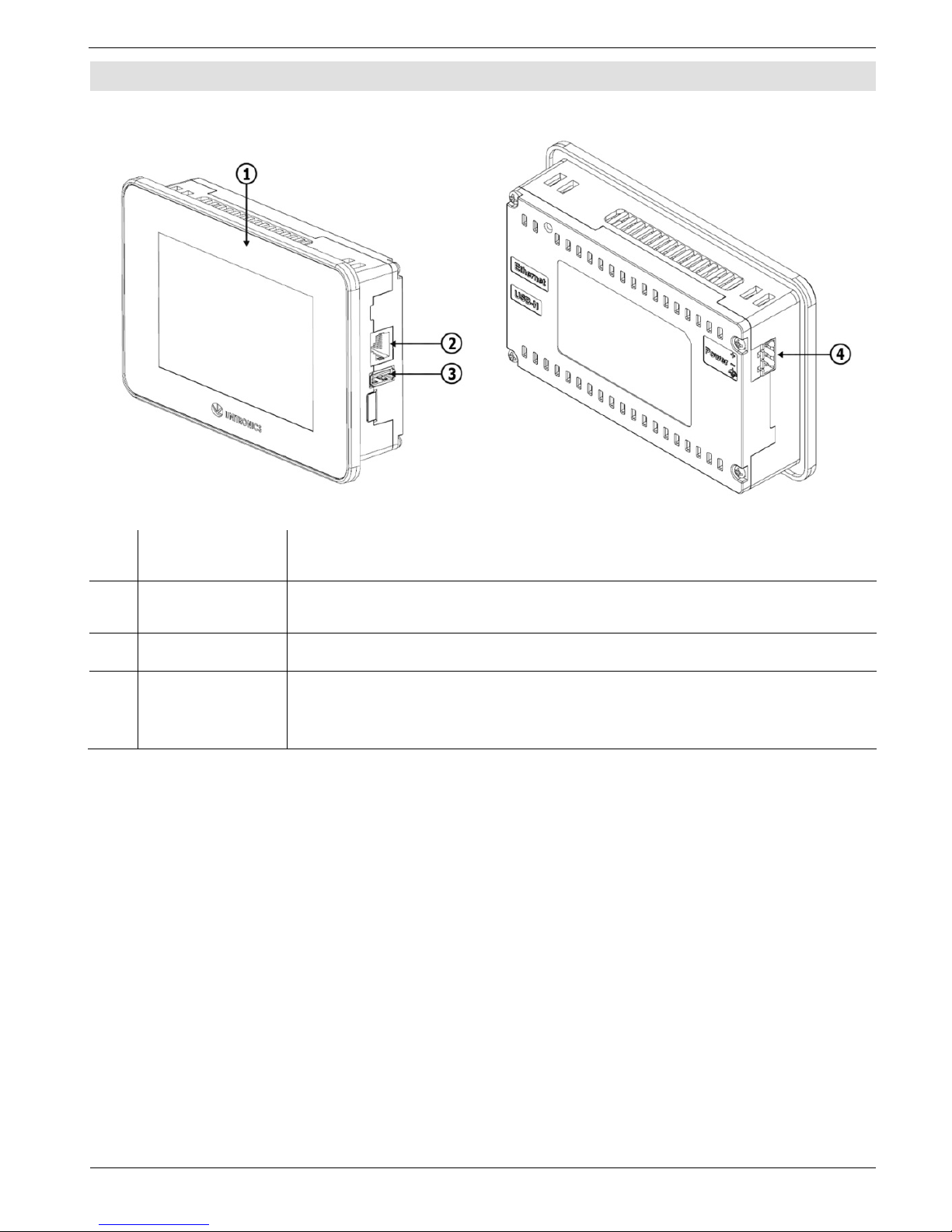
Product Diagram
Front Rear
1
Screen
Protection
A plastic sheet attached to the screen for protection. Remove it
during install at ion.
2 Ethernet port
Enables you to connect the Display to the UniStream P LC via
Ethernet cable.
3 USB Host port Pro v ides t he int erfa ce f or system upda tes and sy ste m l o g access.
4 Power Supply
Input
Connection point for the Display power source.
Connect the Terminal Block supplied with the kit to the end of the
power cable.
4 Unitronics
UniStream® Display
Installation S pace Consider a tion s
Allocate space for:
the device
acce ss to ports
For exact dime nsio ns, please re fer to the Mechanical Dimensions shown below.
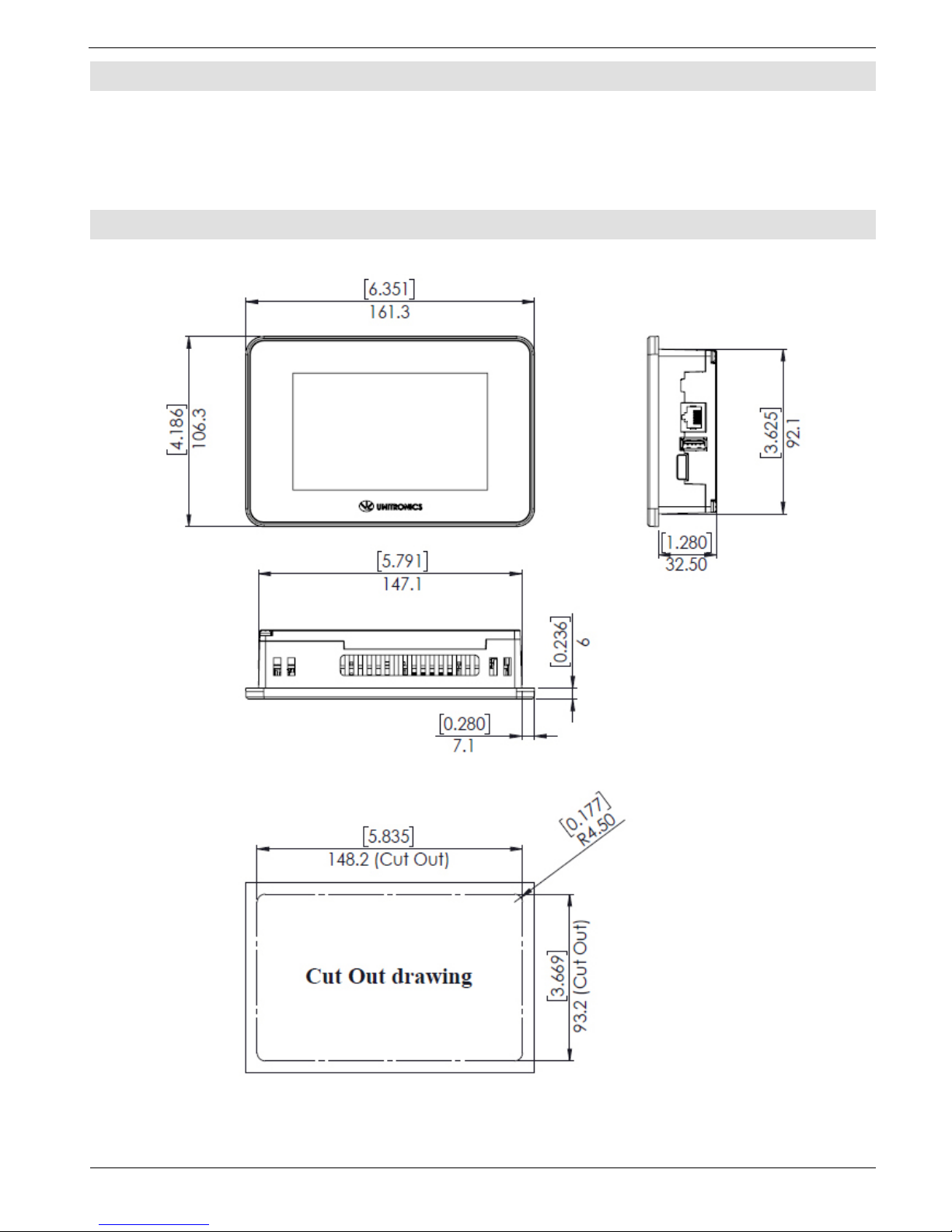
Mechanical Dimensions
USL-050-B05
Unitronics 5

UniStream® Display
USL-070-B05
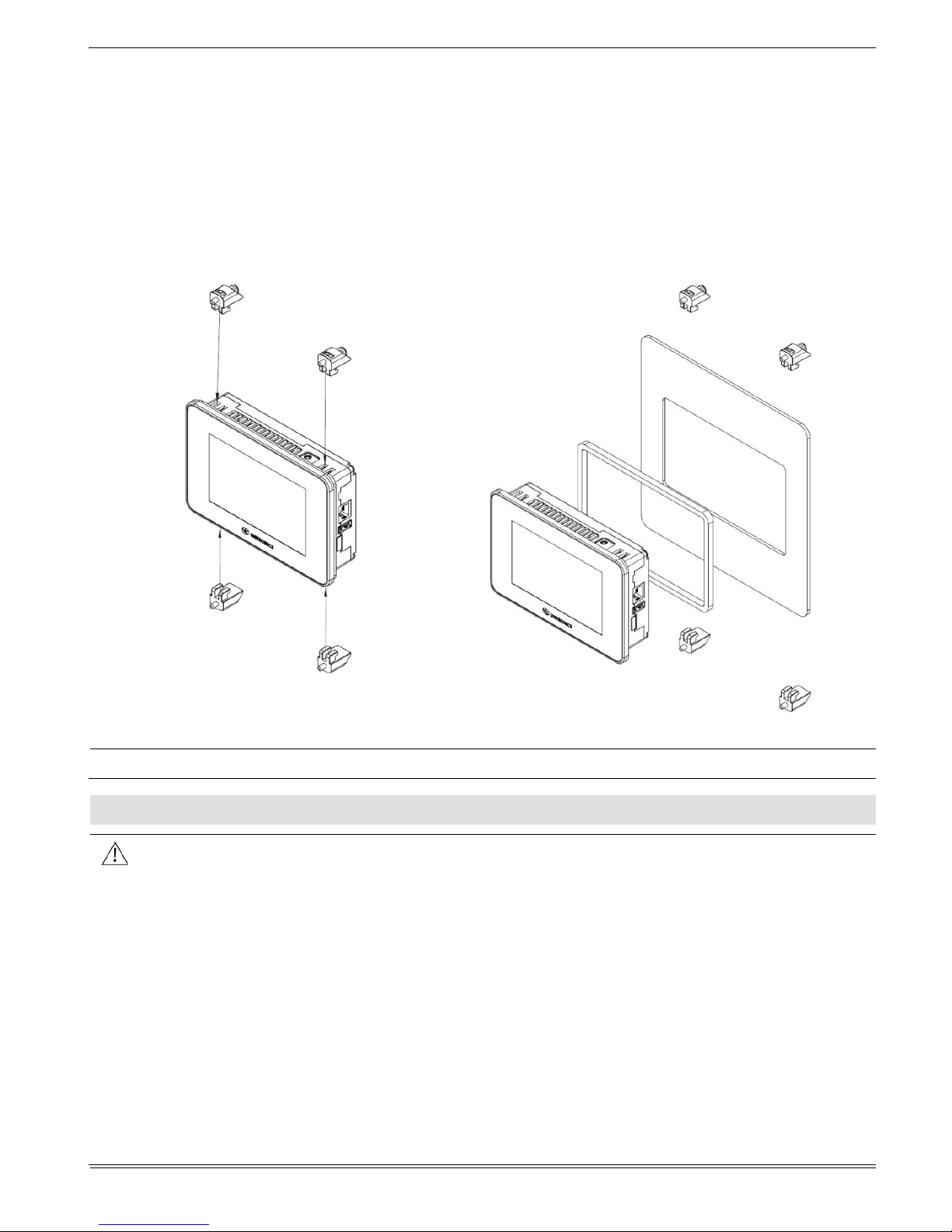
Panel Mounting
NOTE
Mounting panel thickness must be less or equal to 5mm (0.2”).
Ensu r e that the space considerations are m e t.
6 Unitronics
UniStream® Display
1. Prepare a p a n el cu t-out according to the dimensions as shown in the previous section.
2. Slide the device int o the cut-out, ensuring that the Pan el Mounting Seal is in place as
shown below.
3. Push the mounting brackets into their slots on the sides of the panel as shown below.
4. Tighten the bracket screws against t h e p an el. Hold the brackets s ecurely against t h e
unit while tightening the screws.
When properly mounted, the device i s squarely sit uated in t he panel cut-out as sh own
below.
Caution
The necessary torque is 0.35 N·m (3.5 kgf·cm).
\
Wiring
This equipment is designed to operate only at SELV/PELV/Class 2/Li mited Power
environments.
All power supplies in the system must include double insulation. Power supply
outputs must b e rated as SELV/PELV/Class 2/Limited Power.
Do not connect either the ‘Neutral’ or ‘Line’ signal of the 110/220VAC to device’s 0V
point.
Do not touch live wires.
All wiring activit ies should be perfor med while power is OFF.
Use over-cu rren t protecti on, such as a fuse or circuit breaker, to av oid excessive
currents into the power supply connection point.
Unused point s should not be connected (unless otherwise specified). Ignoring this
directive may damag e t h e device.
Double-check all wiring before turning on the power supply.
Unitronics 7
UniStream® Display
Caution
To av oi d damaging th e wire, use a maximu m torque of 0 . 5 N· m (5 kgf·cm).
Do not use tin, solder, or any substance on stripped wire that might cause the
wire stran d to break.
In stall at maximum distance from high-voltage cab les and power equipment.
Wiring Pro c edure
Use c rimp terminals for wiring; use 26-12 AWG wire (0.13 mm2 –3.31 mm2 )
1. Strip the wire to a length of 7±0.5mm (0.250–0.300 in che s).
2. Unscrew the te rminal to its widest position before inse rting a wire.
3. Insert th e wi re completely in t o t h e t erminal to ensure a proper conn e ction .
4. Tighten enough to keep the wire from pulling free.
Wiring Guidelines
In order to ens u re t hat the device will operate properl y and to avoid electromagnet ic
interference:
Use a metal cab i net. Make sure the cabinet and its doors are properly e art hed.
Individually connect each functional ground point ( ) to the earth of the system
(preferab l y to the metal cabin et chassi s).
Use t he shortest and thickest w ires possible: less than 1m (3.3’) in length, minimum
thickness 14 A WG (2 mm
2
).
Connect the power supply 0V to the earth of the system.
Earthing the ca bles' shield:
Connect t he cable shield to t he earth of th e system (preferably to th e metal
cabinet ch assis). Note that the shield must be conn ected only at one end of t he
cable; it is rec ommended t o earth the shield at the Display-side.
Keep shield co nne ctions a s short a s possi ble.
Ensure shield continuity when extending shielded cables.
NOTE
For detailed info rm at ion, refer to the document System Wiring Guideline s,
located in the Technical Library in the Unitronics’ website.
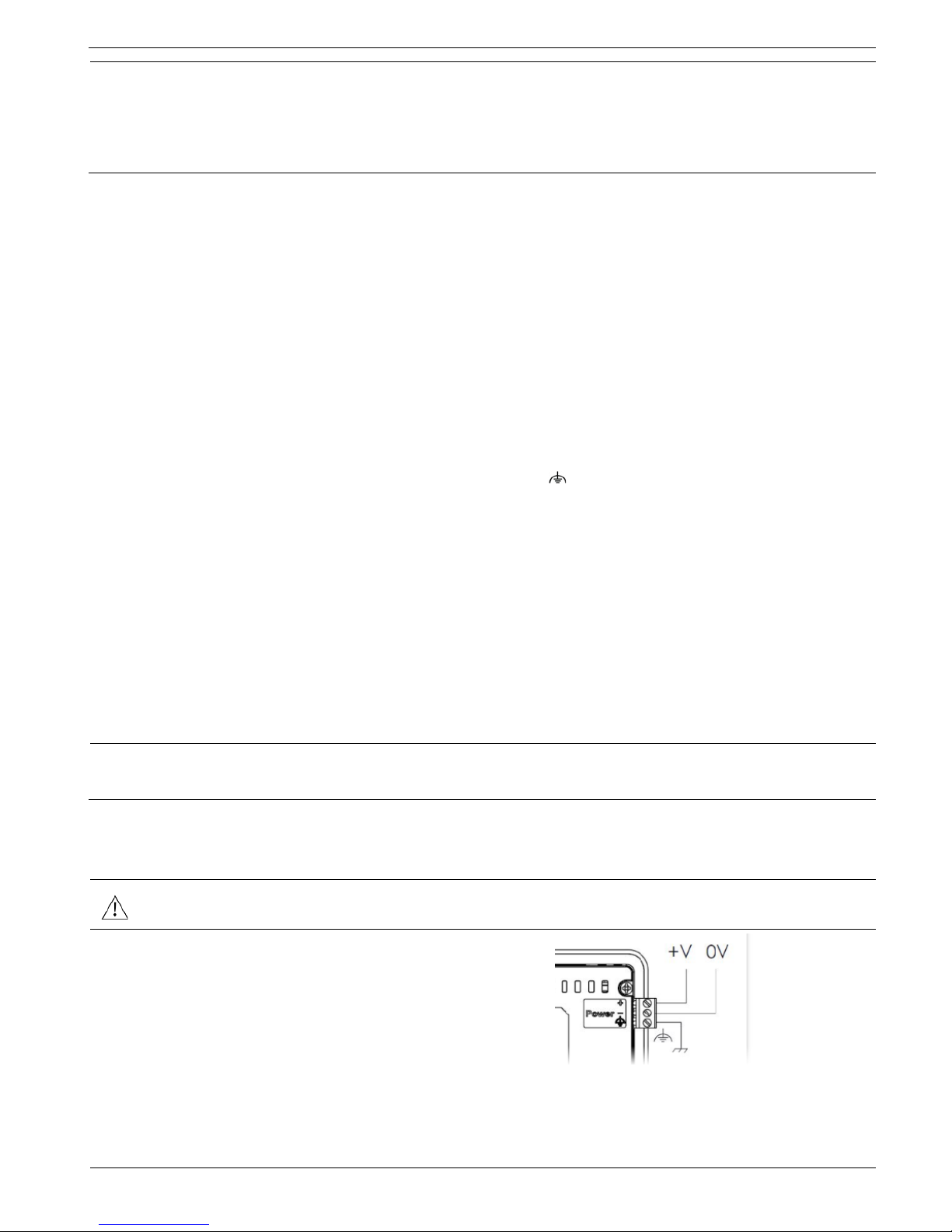
Wi ring the Power Supply
The device requires an external power supp ly.
In the event of voltage fluctuations or non-con formity to volt age power su pply
specifications, connect the device to a regulated power supply.
Connect the +V and 0V terminal s a s
shown in the accompanying figure.
8 Unitronics
UniStream® Display
Connecting Ports
Ethernet
CAT-5e shielded cable with RJ45 connector
USB Host
Standard USB Type-A plug
Uninstalling the Device
1. Disconnect the power supply.
2. Remove all wiring.
3. Unscrew and remove the mounting brackets, taking care to support t h e d ev ice to
prevent it fro m falling d uring t h is procedure.
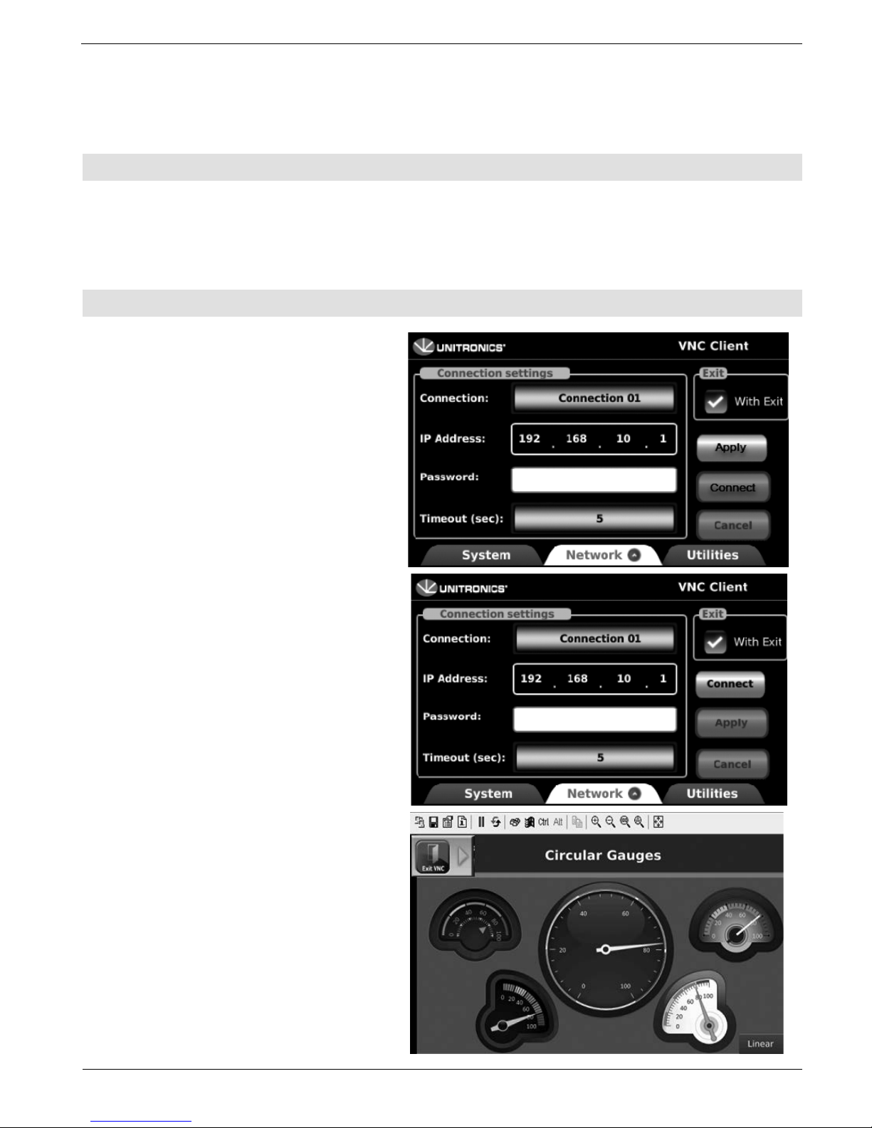
Connecting the Display to a UniStream®
1. After the d ev ice is powered on,
select the Network tab at the
bottom of the screen.
2. Enter the IP Address for the VNC
connection, a password if one is
required by t he VNC server, ed it
the timeout if required, and then
tap Apply.
To add con nections, t ap th e
Connection scroller and repeat the
steps above
1. When a connection i s defi ned,
the Connect button is activated;
tap it to initiate the VNC
connection.
With Exi t
Selecting the Wit h E xit option places
an Exit VNC button on screen during
a VNC session. This can be ta pped in
order to exi t to Uni A pps.
Unitronics 9
UniStream® Display
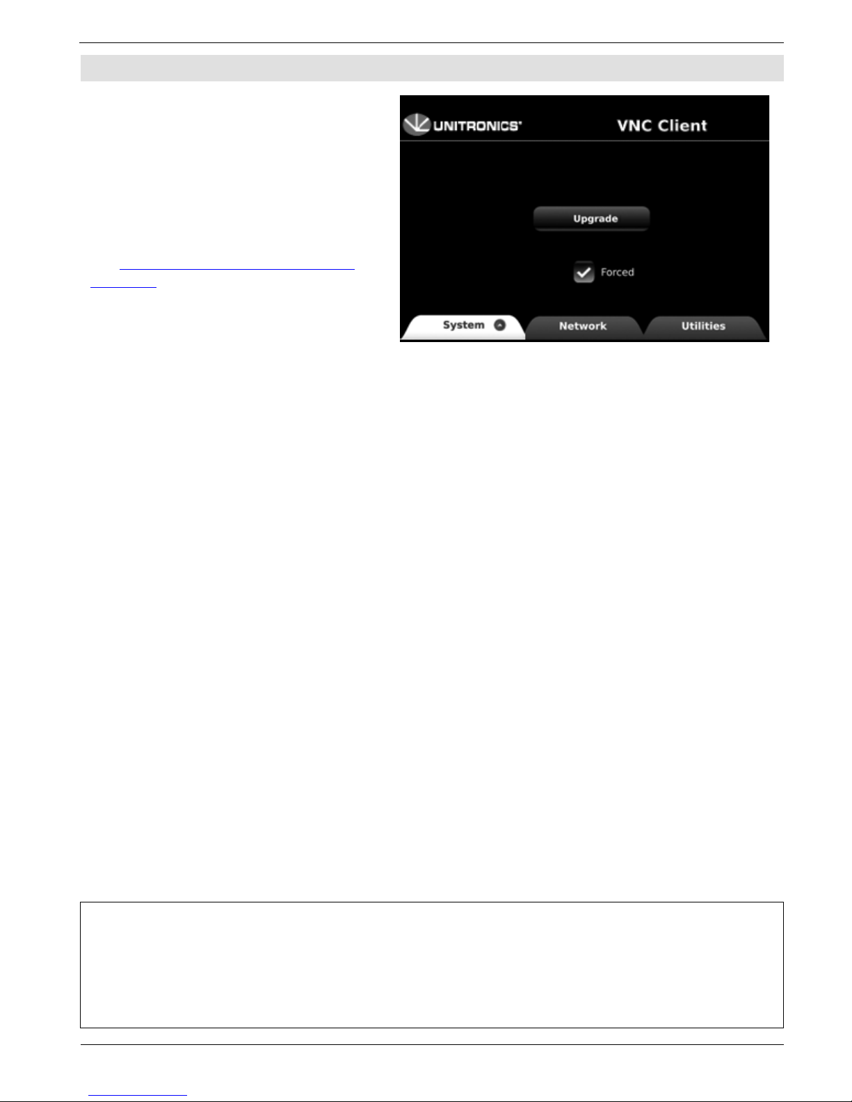
Upgrading Firmware
1. Place a USB f lash drive
containing the firmware update
into the USB port.
2. Select the System tab, tap
Upgrade, and follow the onscre e n instructi o ns.
Note that Firmwa re updates a re
located on t h e Un itronics website, on
the
UniLogic page, under Download
Software.
The info rm ati o n in this do cum en t ref lec ts p rod uc ts at th e date of p ri nti ng. Unit r onics r ese rv es t he ri ght, su bj ect to all ap plicable laws, at any time, at its sole
discretion, and without notice, to discontinue or change the features, designs, materials an d ot he r speci ficati ons of its products, and to either permanently or
temporarily withdraw any of the forgoing from the market.
All information in this document is provided "as is" without warranty of any kind, either expressed or implied, including but no t limite d to any implied
warranties of merchantability, fitness fo r a particular pu rpose, or non-inf ri ng emen t. U ni tro nic s ass um es no resp o nsi bili ty f or e rro rs o r omissi o ns in t he
information presented in this document. In no event shall Unitronics be liable for any spe cia l, inci de n tal, indi rect o r co nse q uenti al damag es of any kind, o r
any damages whatsoever arising out of or in connection with the use or performance of this information.
The tradenames, trademarks, logos and service marks presented in this doc um e n t, inclu di ng thei r desig n, ar e th e pr op e rty of Uni t r oni c s (1 9 8 9) (R"G) Ltd. o r
other third parties and you are not permitted to use them without the prior written consent of Unitronics or such third party as may own them
DOC30013-A7 02/19
10 Unitronics
 Loading...