

Page 1

Unitronics 1
Short-Range Local Expansion Kit
Installation Guide
UAG-XKxxx
& UAG-XKPxxx
Use a Short-Range Local Expansion Kit to expand your I/O configuration by connecting a
UniStream™ CPU controller to Uni-I/O™ modules located on a DIN-rail.
Short-Range Local Expansion Kits are available:
Without power supply
With power supply
This enables a single CPU to support a greater
number of modules
The kit is available with cables of differe nt le ng ths.
Note that the maximum number of modules supporte d
by a single CPU is provided in the CPU’s technic al
specifications.
Before You Begi n
Before installing the dev ic e , the installe r must:
Read and understand this document and re late d tec hni c al spe c ifications and documents
in the Technical library section o f the Unitronics website.
Verify the Kit Contents.
Alert Symbols and General Restrictions
When any of the following symbols appea r , re ad the assoc iated information carefully.
Symbol Meaning Description
Danger The identified danger causes physical and property damage.
Warning The ident if i ed danger could caus e physical and property damage.
Caution Caution Use caution.
All example s and diagr am s are intend e d to aid unders tand i ng , and do not guarantee
operation. Unitro nic s accepts no responsibility for actual use of this prod uc t b ased o n
these examples.
Please d ispose of this pro d uc t accor ding to local and national standards a nd reg ulations.
This prod uc t shoul d be install e d only by qualified personnel.
Failure to comply with appropriate safety guid e line s can cause severe injury or
property damage.
Do not attempt to use this device with param e ters tha t excee d per mis s i b le level s .
Do not connect/dis conne c t the dev ic e whe n power is on.
Environmenta l Consider a tions
Ventilation: 10mm (0.4”) of space is required betwee n the devi ce top/bo ttom edges
and the enclosure’s walls.
Do not install in are as with: exce ssive or conductive dust, corrosive or flammable
gas, moisture or rain, excess ive he a t, regular impac t s hocks or excessive vibration,
in accordance with the standards and limitatio ns given in the product’s technical
specification sheet.
Do not place in water or let water leak onto the unit.
Page 2

Short-Range Local Expansion Kit Installation Guide
2 Unitronics
Do not allow debr is to fall ins ide the unit during installation.
Install at maximum distanc e from high-voltage cables and power equipment.
Kit Contents
Item
Qty
UAG-XKxxx
UAG-XKPxxx
Local Expansion Base Unit
1 √ √
Local Expansion End Unit with
an integrated xxx cm cable.
1 √ -
Local Expansion End Unit with a
power supply and an integrated
xxx cm cable.
1 - √
Terminal Block
1 √ √
Kit Diagram
1
Bus connector
2
Base Unit plug
3 Clips
4
Base Unit’s c a ble port
5
RJ45 connector
6
End Unit LED indicators
7
DIN-rail clips, top and botto m
8
End Unit I/O bus connector
9
I/O Bus - Left side connector
10 Model-dependent:
UAG-XKPxxx power supply connector
UAG-XKxxx earth point connector
Installation Space Considerations
Allocate space for the B a se Unit and End Unit according to the dimens ions in the kit’ s
technical specifica tio ns . A l so, cons ider the space required to install and connect them, as
shown in the following Ins talla tio n ins tructions.
Installation
Turn off syste m power before conne c ting or disconnecting any modules or devices.
Use proper precautions to prevent Ele c tro -Static Discharge (ESD).
This kit enables you to connect a UniStream™ controller to a row of Uni-I/O™ modules
located on a DIN-rail. To do this, you must:
Connect the Base Unit to the last device installe d on the back of the HMI panel. This may
be the CPU-for-Panel, a Uni-COM™ module, or another Uni-I/O™ module.
Connect the End Unit to the first module in a row of Uni-I/O™ modules.
Link the End Unit into the Base Unit via the connecting c able.
If you are using a:
UAG-XKPxxx with power supply, connect it to a power source
UAG-XKxxx without power supply, earth it.
Page 3
UniStream™Uni-I/O™
Unitronics 3
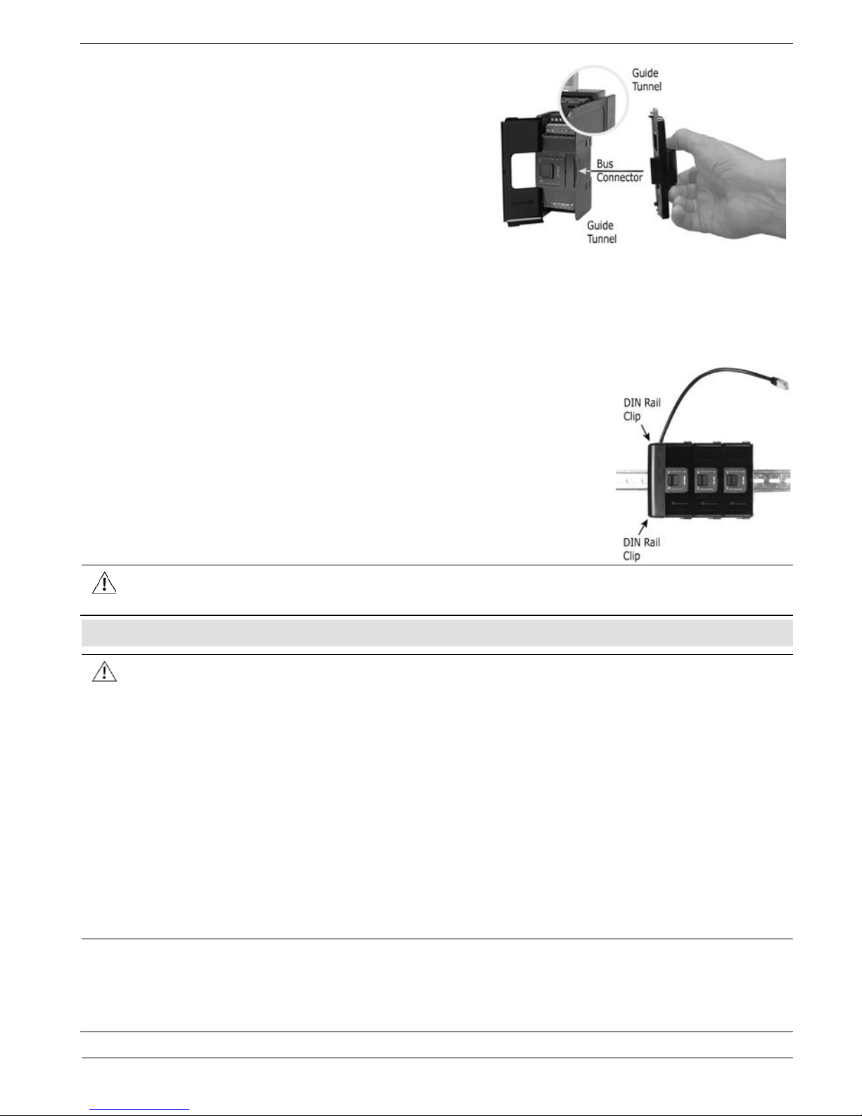
Connecting the Base Unit
1. Check the unit to which you will connect the
Base Unit to verify that its Bus Connector is
not covered.
2. Hold the Base Unit as shown in the
accompanying figure, and plug it into the last
device installed on the back of the HMI panel.
3. Click the top and bottom clips into the Guide
Tunnel of the last device.
Connecting the End Unit
1. Push the End Unit onto the DIN-rail until the clips located at the top and bottom of the
unit have snapped onto the DIN-rail.
2. Install Uni-I/O™ modules to the right of the End unit. Please refer to the specific
Installation Guide of e ach Uni-I /O™ module.
3. Slide the Bus Connector Lock of the fir s t module all the way to
the left.
4. Link the units by plugging the RJ45 of the End Unit’s ca b le into
the port on the bottom of the Base Unit.
5. If you are using a:
UAG-XKPxxx with power supply, connect it to a power source
as described on page 4.
UAG-XKxxx without power supply, earth it.
Do not connec t the cable to any devi c e other tha n the Base Unit.
Do not connec t the Base Unit’s c able por t to any othe r cable or devic e .
Wiring
This equip m e nt is desig ned to oper ate o nly at SELV/PELV /Class 2/Limited Power
environments.
All power s upp lie s in the sys tem must inc l ud e doub le insulati o n. Power supply
outputs must be rated as SELV/PELV/Clas s 2/Limite d Power.
Do not connec t either the ‘ Neutr al’ or ‘Line’ signal of the 110/220VAC to devi c e ’s 0V
point.
Do not touch live wire s .
All wiri ng activities should be performed while power is OFF.
Use over-curr e nt pro te c tio n, such as a fuse or circuit bre aker, to avoid excessive
currents into the UAG-XKPxxx supply port.
Unused points should not be connected (unless otherwise specified). Ignoring this
directive may damage the device.
Double-check all wiring before turning on the power supply .
Caution
To avoid damaging the wire , use a maximum torq ue of 0.5 N·m (5 kgf·cm).
Do not use tin, solder, or any subs tanc e on strip pe d wire that might c aus e the
wire strand to break.
Install at maxim um d i s tanc e from high-voltage cables and power equipment.
Page 4
Short-Range Local Expansion Kit Installation Guide
4 Unitronics
Wiring Procedure
Use crimp terminals for wiring; use 26 -12 AWG wire (0.13 mm2 –3.31 mm2).
1. Strip the wire to a length of 7±0.5mm (0.250–0 .300 inche s).
2. Unscrew the terminal to its wides t position before inserting a wire.
3. Insert the wire completely into the termi nal to ens ure a proper conne c tion.
4. Tighten enough to keep the wire from pulling fr e e .
Wiring Guidelines
In order to ensure that the device will operate properly and to avoid electromagnetic
interference:
Use a metal cabinet. Make sure the cabinet and its door s are pr op erly earthed.
Use wires that are properly sized for the load.
Connect the 0V point o f the UAG-XKPxxx directly to the power supply 0V term inal.
Connect the functional ground point ( ) to the earth of the system (preferably to the
metal cabinet chassis).
Use the shortest and thickest wire s poss ible: less than 1m (3.3’) in length, minimum
thickness 14 AWG (2 mm2).
Connect the power supply 0V to the earth of the system.
N
OTE
For detailed informatio n, refer to the document System Wiring Guideline s , loc ate d in
the Technical Library in the Unitronic s ’ website.
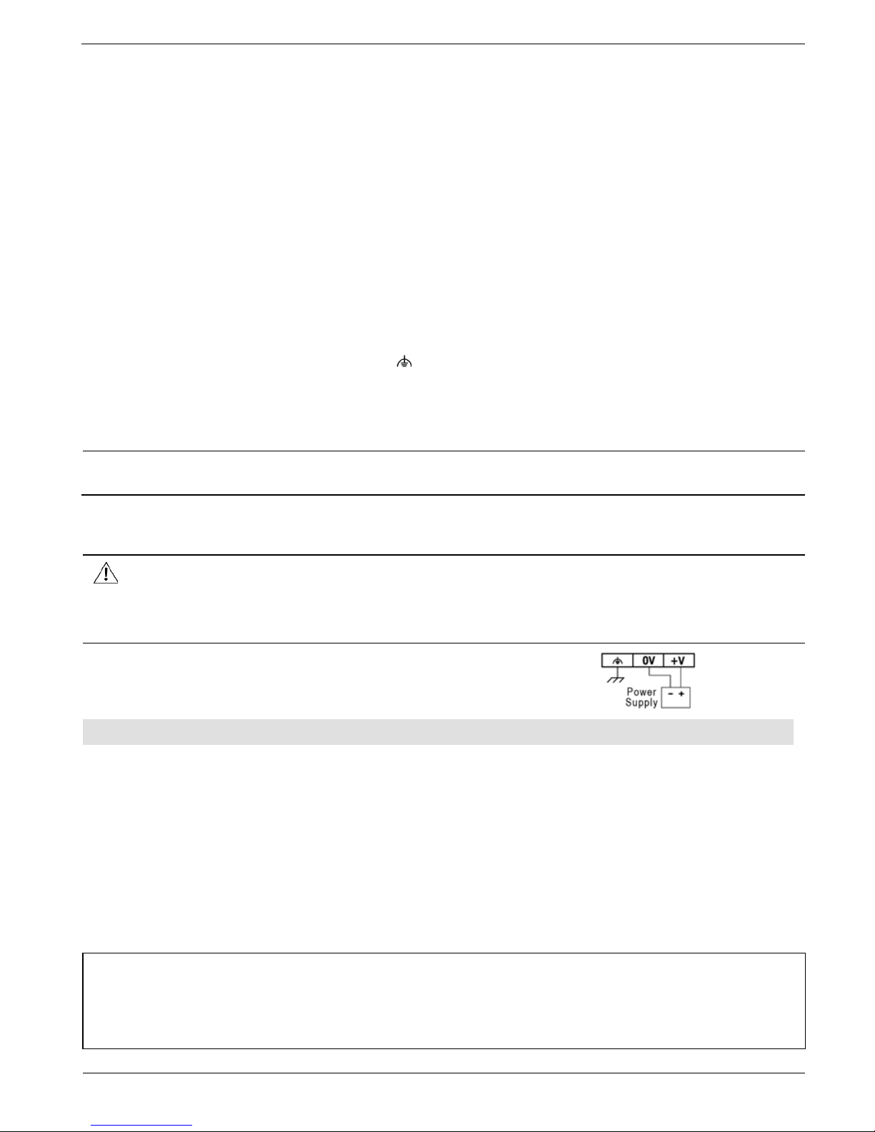
13BWiring the Power Supply (UAG-XKPxxx)
The UAG-XKPxxx requires an external 12 or 24VDC power supply.
The 0V of the UAG-XKPxxx end unit must be connected to the HMI Panel’s 0V.
Ignoring this directive may damage the device.
In the event of voltage fluc tuations or non-conformity to voltage power supp ly
specifications, conne c t the devic e to a regulated power supply.
Connect the +V and 0V terminals as s hown in the
accompanying figure.
7BRemoving the E x pansion Cable
1. Turn off the system power.
2. Unplug the cable from the Base Unit.
3. To remove the Base unit, pull the top clip up and the bottom clip down; and pull it
slowly away until the plug disengages.
4. To remove the End unit:
• Locate the Bus connector lock of the Uni-I/O™ module connected to the End Unit
and slide it to the right.
• Pull the End Unit’s top DIN-rail clip up and the bottom clip down.
• Pull the End Unit out of its place (away from the DIN rail).
The information in this document reflects products at the date of printing. Unitronics reserves the right, subject to all applicable laws, at any time, at its sole d is cret io n, a nd wit hou t n oti ce,
to discontinue or change the features, designs, materials and other specifications of its products, and to either permanently or temporarily withdraw any of the forgoing from the
market.All information in this document is provided "as is" without warranty of any kind, either expressed or implied, including but not limited to any implied warranties of merchantability,
fitness for a particular purpose, or non-infringement. Unitronics assumes no responsibility for errors or omissions in the information presented in this document. In no event shall
Unitronics be liable for any special, incidental, indirect or consequential damages of any kind, or any damages whatsoever arising out of or in connection with the use or performance of
this information. The tradenames, trademarks, logos and service marks presented in this document, including their design, are the property of Unitronics (1989) (R"G) Ltd. or other third
parties and you are not permitted to use them without the prior written consent of Unitronics or such third party as may own them
[DOC27006-A1] 04/13
 Loading...