

Page 1

Z12
STEREO MICROSCOPE
MANUAL
73 Mall Drive, Commack, NY 11725 • 631-543-2000 (P) • 631-589-6975 (F)
www.unitronusa.com • info@unitronusa.com
Page 2

Page 3

Z12 ZOOM STEREO MICROSCOPE
CONTENTS
SAFETY NO TES ................................................................................................................... 3
CARE AND MAINTENANCE ................................................................................................ 3
INTRODUCTION .................................................................................................................. 4
UNPACKING AND COMPONENTS ..................................................................................... 4
COMPONENT DIAGRAMS .................................................................................................. 5
ASSEMBLY DIAGRAM ......................................................................................................... 6
DETAILED ASSEMBLY ..................................................................................................... 7-9
OPERATION
ILLUMINATION ........................................................................................................................ 10
REFLECTOR............................................................................................................................ 10
FOCUSING TENSION .............................................................................................................. 10
DIOPTER & FOCUSING .......................................................................................................... 11
INTERPUPILLARY DISTANCE ................................................................................................ 11
VIEWING ANGLE ..................................................................................................................... 11
CLICK/CLICK STOP................................................................................................................. 12
EYEGUARDS ........................................................................................................................... 12
APERTURE DIAPHRAGM ....................................................................................................... 13
LIGHT PATH ........................................................................................................................... 13
MOUNTING A MICROSCOPY CAMERA (OPTIONAL) ........................................................... 13
POLARIZER/ANALYZER ......................................................................................................... 14
TROUBLESHOOTING ................................................................................................... 15-16
MAINTENANCE .................................................................................................................. 17
SERVICE ............................................................................................................................ 17
WARRANTY ....................................................................................................................... 17
UNI
TRON
73 Mall Drive, Commack, NY 11725 • 631-543-2000 • www.unitronusa.com 2
Page 4

Z12 ZOOM STEREO MICROSCOPE
SAFETY NOTES
1. Open the shipping carton c ar ef ul ly to prevent any accessory , i.e. objectives or eyepieces, fro m dropping
and being damaged.
2. Do not discard the molded shipping carton; the contain er should be retained should the microscope ever
require reshipment.
3. Keep the instrument out of direct sunlight, high temp er at ur e or humidity, and dusty environments. Ensure
the microscope is located on a smooth, level and firm surface.
4. If any specimen solutions or ot her li qui ds s plash onto the stage, objective or any other component ,
disconnect the power cord immediately and wipe up the spillage. Otherwise, the instrument may be
damaged.
5. All electrical connectors (power cord) should be inse r t ed int o an electrical surge suppressor t o prevent
damage due to voltage fluctuations.
6. LAMP REPLACEMENT -- CAUTION: the glass housing of t he l amp may be extremely hot.
DO NOT attempt to chang e the lamp before it is complete ly c ool ed or w it hout wearing
adequate skin protection.
7. FUSE REPLACEMENT -- For safety when replac in g the fuse (ONLY replace w ith t he same
size, type and rating of origin al fus e) , be sure the main switch is in the off position, disconnect
the power cord from outlet, and r epla ce the fuse. Reconnect the pow er cor d and turn unit on.
8. Confirm that the input voltage indicated on your micr oscope corresponds to your line v olt age. The use of a
different input voltage other than indicated will cause severe damage to the microscope.
CARE AND MA INTE NANCE
1. Do not attempt to disasse mb le a ny component including ey epie ces , objectives or focusing assembly.
2. Keep the instrument clean ; r emov e dirt and debris regularly. Accumulated dirt on metal surfaces should be
cleaned with a damp cloth. M or e per sistent dirt should be removed using a mild soap solution. Do not use
organic solvents for cleansing.
3. The outer surface of the opt ics should be inspected and clean ed periodically using an air stream from an
air bulb. If dirt remains on the optical surface, use a soft cloth or c ot t on swab dampened with a lens
cleaning solution (available at camera stores). All optical lenses should be swabbed using a circular
motion. A small amount of absor bent cotton wound on the end of a tapered stick such as cott on swabs or
Q-tips, makes a useful tool for cleani ng r ecessed optical surface s. Avoid using an excessive am ount of
solvents as this may cause pr oblems with optical coatings or cemented optics or the flowing solvent may
pick up grease making cleani ng more difficult.
4. Store the instrument in a c ool, dr y environment. Cover t he m icroscope with the dust cover when not in
use.
5. UNITRON® microscopes are precision instruments which req uire periodic preventat ive maintenance to
maintain proper perform ance and to compensate fo r nor m al wear . A n annual schedule of preventative
maintenance by qualified personnel is highly recommended. Your authorized UNITRON
arrange for this service.
®
distributor can
UNITRON
73 Mall Drive, Commack, NY 11725 • 631-543-2000 • www.unitronusa.com 3
Page 5

Z12 ZOOM STEREO MICROSCOPE
INTRODUCTION
Congratulations on the purchase of your new UNITRON® microscope. UNITRON® microscopes are
engineered and manufactured to the highest quality standards. Your microscope will last a lifetime if used
and maintained properly. UNITRON
staff of trained technicians in our New York facility. Careful quality control procedures ensure each
microscope is of the highest quality prior to shipment.
®
microscopes are carefully assembled, inspected and tested by our
UNPACKING AND COMPONENTS
Your microscope arrived packed in a molded shipping carton. Do not discard the carton: the carton
should be retained for reshipment of your microscope if needed. Avoid placing the microscope in dusty
surroundings or in high temperature or humid areas as mold and mildew will form. Carefully remove the
microscope from the EPE foam container by its arm and base and place the microscope on a flat,
vibration-free surface. Check the components against the packing list included with your microscope.
UNITRON
73 Mall Drive, Commack, NY 11725 • 631-543-2000 • www.unitronusa.com 4
Page 6

Trinocular
Aperture
Coarse/Fine Focus
Adjustment Knobs
Eyepiece
Stage Insert
Camera/Photo
Port
Focus
Tension
Zoom
Lock Knob
Stage Clip
Light Path
Selection Slider
Objective
Base
Reflector
Microscope
COMPONENTS DIAGRAM
Z12 ZOOM STEREO MICROSCOPE
Diaphragm
Control
Body
Adjustment Collar
Viewing Head
Knob
Drive
Plate
UNITRON
Adjustment
Knob
73 Mall Drive, Commack, NY 11725 • 631-543-2000 • www.unitronusa.com 5
Page 7

Z12 ZOOM STEREO MICROSCOPE
ASSEMBLY DIAGRAM
The diagram below shows how to assemble the various components. The numbers indicate the order of
assembly. Use the 1.5mm and 3mm hex wrenches that are supplied with your microscope when
required. Be sure to keep this wrench for changing out components or making adjustments.
When assembling the microscope, make sure that all parts are free of dust and dirt, and avoid scratching
any parts or touching glass surfaces.
⑤
① Focus Drive
② Microscope Body
④
③
⑥
②
⑦
①
⑨
⑧
③ Objective
④ Trinocular Viewing Head
⑤ Eyepieces
⑥ Stage Insert Plate
⑦ Stage Clips
⑧ Illuminator Light Guide
⑨ Illuminator Power Cord
UNITRON
73 Mall Drive, Commack, NY 11725 • 631-543-2000 • www.unitronusa.com 6
Page 8

Mount the Focus Drive (Fig. 1-2)
①
③
Fig. 1
②
Fig. 2
Correct
X
Wrong!
④
Fig. 3
Fig. 4
① ③ ② ① ②
DETAILED ASSEMBLY
Z12 ZOOM STEREO MICROSCOPE
Loosen the lock knob ① of the focus dri ve ②. Position the
focus drive as shown and gently slide it all the way down
onto the column pole ③ until the bottom of the focus drive is
flush with the column base ④, Fig. 2.
Tighten the lock knob.
WARNING: the focus drive MUST be mounted correctly as
shown in Fig. 2. Mounting it improperly will result in the
microscope tipping over which may cause damage.
Mount the Microscope Body (Fig. 3)
Remove the access cap ① on the side of the focus group
and loosen the screw inside with a 3mm hex wrench.
Carefully slide the microscope body ② onto the dovetail
interface ③ of the focus group as shown.
Tighten the lock screw on the focus group and replace the
access cap.
Install the Objective (Fig. 4)
Carefully position and screw the objective ① into the
bottom ② of the microscope body by rotating it clockwise as
shown until it stops.
DO NOT force it on or overtighten it.
UNITRON
73 Mall Drive, Commack, NY 11725 • 631-543-2000 • www.unitronusa.com 7
Page 9
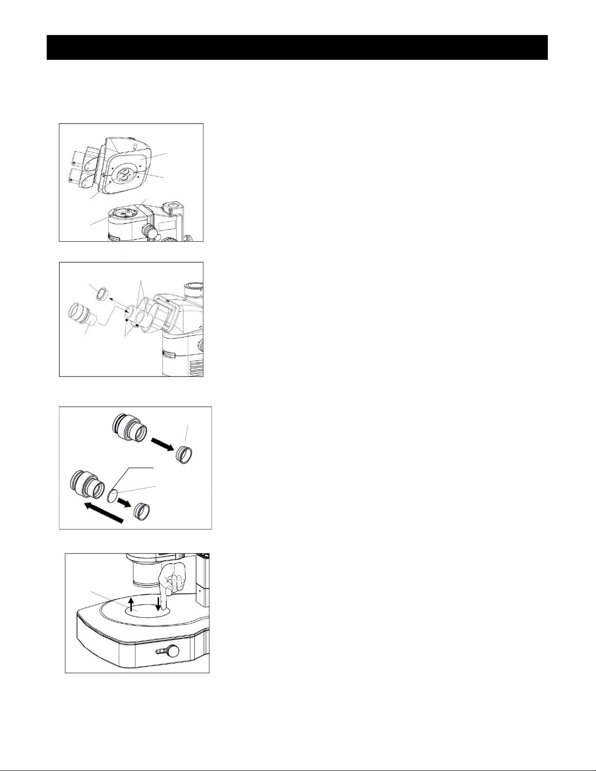
Mount the Viewing Head (Fig. 5-6)
①
⑤
Fig. 5
③
Fig. 6
Fig. 7
Fig. 8
① ② ④ ⑥ ⑦
⑧
⑨
Inscription Side
①
②
DETAILED ASSEMBLY - continued
Z12 ZOOM STEREO MICROSCOPE
Loosen the lock screw ① on the front of the microscope
body with the 3mm mm hex wrench.
With the eyepiece tubes ② facing forward (as shown in
Fig. 6), carefully slide the dovetail ③ (Fig. 5) on the bottom
of the viewing head ④ (Fig. 5) onto the dovetail mount on
the top of the microscope body by aligning the orientation
groove ⑤ with the orientation pin ⑥ of the microscope
body. Make sure it is seated properly (it should be level and
not wobble), then tighten the lock screw.
Install the Eyepieces (Fig. 6)
Remove the eyetube caps ⑦ and insert the eyepieces ⑧
into the eyepiece tubes ②.
Lock in the eyepieces by tightening the thumbs screws ⑨
on each eyepiece tube.
Mount/Unmount the Eyepiece Reticle (Fig. 7)
To mount the reticle: unscrew the mounting ring ① from
the eyepiece by turning it counterclockwise.
Clean the reticle ② and insert it into the mounting ring with
the inscription side as shown.
Screw the mounting ring back onto the eyepiece.
To remove the reticle: unscrew the mounting ring from the
eyepiece, then carefully take out the reticle and wrap it in
clean, soft, lin t-free paper for storage.
Screw the mounting ring back onto the eyepiece.
Install the Stage Insert Plate (Fig. 8)
Gently push the stage insert plate ① with the edge tilted
toward the spring on the inside of the hole in the base and
set it into place.
To remove the stage insert plate, press down with one finger
near the spring – it will pop up on the opposite side and you
can then lift it out.
UNITRON
73 Mall Drive, Commack, NY 11725 • 631-543-2000 • www.unitronusa.com 8
Page 10

Install the Stage Clips (Fig. 9)
①
②
Fig. 9
③
Fig. 10
① ② ④ ⑤ ⑥ ⑦ ⑧
⑨
DETAILED ASSEMBLY - continued
Z12 ZOOM STEREO MICROSCOPE
Insert the stage clip post of the stage clip ① into the hole ②
on the top of the base as shown; repeat for other stage clip.
Connect the LED Illuminat or & P ow er S upply
(Fig. 10)
Make sure the power switch on the illuminator ① is set to
“OFF”.
Align the end of the flat part of the illuminator light guide ②
with the lock screw ③ on the socket ④ on the front of the
illuminator and slide it in and tighten the lock screw.
Insert the other end of the illuminator light guide into the
socket ⑤ on the back of the microscope and tighten the lock
screw on the top of the socket.
Insert one end ⑥ of the power cord on the power supply ⑦
into the socket ⑧ on the back of the illuminator.
Plug the other end ⑨ into the corresponding socket on the
other end of the power supply.
Plug the other end of the power supply into a grounded (3prong) outlet.
NOTE: Always use the power cord that is provided with your
microscope; using a different power cord may damage your
microscope. Should you need a replacement, contact your
authorized UNITRON dealer or call UNITRON at 1-631-5432000 for a dealer nearest you.
UNITRON
73 Mall Drive, Commack, NY 11725 • 631-543-2000 • www.unitronusa.com 9
Page 11

Adjusting the Illuminat ion (Fig. 11)
②
①
Fig. 11
Fig. 12
Fig. 13
① ① ②
③
OPERATION
Z12 ZOOM STEREO MICROSCOPE
Turn the power switch ① to “ON”.
NOTE: For longer lamp lif e always turn the light
intensity control knob ② to the lowest illumination
intensity setting possible before turning the power on or
off.
The light level may need adjustment depending upon
the specimen density and objective magnification.
Adjust the light intensity for comfortable viewing by
turning the light intensity control knob clockwise to
increase brightness. Turn counterclockwise to
decrease brightness.
Adjusting the Reflector (Fig. 12)
The reflector has two sides: one is a plane mirror, the
other is sandblasted aluminum. Both sides reflect light
but the plane mirror is provides a stronger reflection.
You can change the reflector type or the reflection
intensity by rotating the reflector adjustment knob ①.
The reflector adjustment knob can also be moved from
front to back to achieve different lighting effects of the
reflector.
Adjusting the Focusing Tension (Fig. 13)
If the feel is very heavy when focusing with the focusing
knobs ①, or the specimen leaves the focus plane after
focusing, adjust the tension with the tension adjustment
ring ②.
Turn the tension adjustment ring clockwise to tighten or
counterclockwise to loosen according to user
preference.
UNITRON
73 Mall Drive, Commack, NY 11725 • 631-543-2000 • www.unitronusa.com 10
Page 12

Adjusting the Diopter & Focus (Fig. 14)
Left Diopter
Right Diopter
Fig. 14
Fig. 16
Fig. 15
OPERATION (continued)
Z12 ZOOM STEREO MICROSCOPE
Adjustment Ring
Adjustment Ring
Set the dioptor rings of both eyepieces to “0” position.
(Do this when users change, because different users
will have different diopter settings.)
Place an easy-to-observe specimen on the stage plate,
i.e., a coin.
Rotate the zoom knob to the highest magnification, then
turn the focusing knob to focus the specimen.
Rotate the zoom knob to the lowest magnification,
looking only into the left eyepiece, adjust the diopter
ring on left eyepiece to focus the specimen.
Repeat procedure for the right eyepiece.
Adjusting Interpupi llary Distance (Fig. 15)
To adjust the interpupillary distance, hold the left and
right eyetubes while observing a specimen. Rotate the
eyetubes around the central axis until the fields of view
of both eyetubes coincide completely. A complete circle
should be seen in the viewing field when viewing the
specimen slide. An improper adjustment will cause
operator fatigue and will disrupt the objective
parfocality.
Adjusting the Viewing Angle (Fig. 16)
To adjust the viewing angle, hold the eyepiece tubes
with both hands and move them up or down to the
position that feels most comfortable.
The angle can be adjusted from 5° to 45°.
UNITRON
73 Mall Drive, Commack, NY 11725 • 631-543-2000 • www.unitronusa.com 11
Page 13

Changing the Click/Click Stop Feature
down eyeguards.
Click
Fig. 17
Fig. 18
①
OPERATION (continued)
Click Stop
Z12 ZOOM STEREO MICROSCOPE
(Fig. 17)
The microscope is equipped with a Click/Click Stop
feature that enables the user to set the magnification
value indicated on the zoom knob to stop at each fixed
magnification and will make a “click” sound, or to finely
adjust the zoom magnification.
To turn on the Click feature to click at each
magnification value, using a 3mm hex wrench, turn the
Click/Click Stop screw ① clock wise as shown by the
arrow in Fig. 17.
To turn on the Click Stop feature to finely adjust the
zoom magnification, using a 3mm hex wrench, turn the
Click/Click Stop screw ① counterclockwise.
NOTE: Be careful not to overturn the screw for either
position as it may result in damage to the housing and
internal mechanisms of the microscope.
Adjusting the Eyepiece Eyeguards
(Fig. 18)
The eyepieces come standard with rollThe eyeguards should be rolled down ① for users
wearing eyeglasses to prevent them from being too far
from observing through the eyepieces. Or, not rolled
down ② for those who don’t wear glasses to prevent
extraneous light from entering the eyepiece which may
interfere with specimen observation.
UNITRON
73 Mall Drive, Commack, NY 11725 • 631-543-2000 • www.unitronusa.com 12
Page 14

Adjusting the Aperture Di a phragm
screw ⑤.
①
Fig. 19
Fig 20
① ② ① ② ③ ⑥ ④ ⑤ ⑦
Fig 21
OPERATION (continued)
Z12 ZOOM STEREO MICROSCOPE
(Fig. 19)
Adjust the aperture diaphragm by the aperture
diaphragm control ①.
To enlarge the aperture diaphragm, slide the control to
the left until the desired contrast of the observed image
is achieved.
To decrease the aperture diaphragm, slide the control to
the right until the desired contrast of the observed image
is achieved.
Selecting the Light Pat h (Fig. 20)
The Z12 is outfitted with a binocular viewing head with
one photo port for HDMI/digital imaging. You must
select the appropriate light path for observing
specimens.
The light path is set to 100% to the binocular eye-pieces
as the default setting at our facilities where the light path
selection slider ① is pushed all the way in.
Pull the light path selection slider all the way out to send
100% to the top photo port for HDMI/digital imaging and
documentation.
Mounting a Microscop y Camera (Optional)
(Fig. 21)
Loosen the lock screw ① on the camera/photo port un til it
is flush with the inside of the portl remov e the dust cap ②.
Remove the dust caps from both ends of the c-mount ③
and from your camera lens and at tach the top opening ④
on the c-mount to the threaded mount on your camera.
Attach the bottom dovetail mount of the c-mount (with the
mounted camera) onto the camera/photo port and tighten
the lock screw ⑤.
Focus the image in the binocular view then pull the light
path selection lever out ⑥. If the image is not clear,
loosen the lock screw ⑤ and adjust the focusing sc r ew ⑦
until the image is clear on the monitor, then tighten the lock
UNITRON
73 Mall Drive, Commack, NY 11725 • 631-543-2000 • www.unitronusa.com 13
Page 15

①
Fig. 22
② ⑥ ③
⑤
④
Z12 ZOOM STEREO ICAL MICROSCOPE
OPERATION (continued)
Using the Polarizer/Analyzer (Fig. 22)
The simple polarizer includes the polarizer and
analyzer.
Remove the stage insert plate ① (see Fig. 8, p. 3).
Insert the polarizer ② with the flat edge closest to
the column (or aligned with the spring on the inside of
the hole in the base)
3mm hex wrench. Replace the stage insert plate.
Slide the analyzer ③ onto the bottom outside
diameter of the objective ④ and tighten the analyzer
lock screw ⑤.
With the 360° rotating analyzer, you can change the
orthogonal state of the polarized light by rotating the
analyzer adjustment ring ⑥.
, and screw it in place using the
UNITRON
73 Mall Drive, Commack, NY 11725 • 631-543-2000 • www.unitronusa.com 14
Page 16

The brightness is set too low
Set it to the appropriate position
The field diaphragm is not open enough or
closed
Reduce them to the minimum required
Turn the nosepiece into the position where
you can hear it engaged
Dirt or dust has accumulated on the lens
(objective or eyepieces)
Light path selection slider is not in the right
position
The color filter, polarizer or analyzer is not
inserted fully
Dirt/dust on the specimen
Replace with a clean specimen
Cover glass on the specimen slide
Clean the specimen
The specimen is not vertical to the objective
Adjust it
The nosepiece is not in the correct position
Turn the nosepiece into the correct position
The aperture diaphragm is not open correctly
Adjust it
The light path selection slider is not in the
correct position
The objective is not correctly engaged in the
the aperture diaphragm is opened or stopped
down too far in brightfield observation
The lens (condenser, objective, eyepieces)
The objective is not in the center of the light
Insure the nosepiece is in the “clicked”
The specimen is not correctly positioned on
The eyepiece for the right eye is different from
Z12 ZOOM STEREO MICROSCOPE
TROUBLESHOOTING
Under certain conditions, performance of this unit may be adversely affected by factor s other than defects. If a
problem occurs, please re view the following list and take remedial action as needed. If you cannot solve the
problem after checking the ent ire list, please contact your local dealer for assistance.
OPTICAL
PROBLEM CAUSE
The illumination is on, but the
field of view is dark.
The edge of the field of view is
obscured or not evenly
illuminated.
Dirt or dust is visible in the field
of view
The image is not clear
SOLUTION
The bulb is burnt out. Replace it with a new one
Open the field diaphragm
Too many filters are in the optical path
The nosepiece is not in the located position
Dirt/dust on the eyepiece Clean the eyepieces
number
Clean the lens
Pull it into the right position
Push it in all the way
Push it into the correct position
Visibility is poor
Image is not sharp
Contrast is poor
Details are indistinct
One side of the image is dark,
blurred or it moves while
focusing
The eyes tire easily; the right
field of view doesn’t
superimpose with the left
UNITRON
73 Mall Drive, Commack, NY 11725 • 631-543-2000 • www.unitronusa.com 15
light path
are dirty
path
the stage
Interpupillary distance is incorrect Adjust the interpupillary distance
Diopter adjustment is incorrect Adjust the diopter
the left one
Turn the nosepiece into the engaged position
adjust the aperture diaphragm properly
Clean it thoroughly
position
Reposition the specimen on the stage
Use the same eyepieces
Page 17

TROUBLESHOOTING (continued)
MECHANICAL PART
Z12 ZOOM STEREO MICROSCOPE
PROBLEM CAUSE
The coarse adjustment knob is
too difficult to rotate
The image goes out of focus
during observation or the stage
drops by itself
The tension adjustment ring is tightened too
much
The tension adjustment collar is too loose Tighten it
Loosen it
SOLUTION
ELECTRICAL SYSTEM
PROBLEM CAUSE
No power to the lamp Check the power cord is connected correctly
The lamp doesn’t light
The light intensity is not
enough
The lamp keeps burning out The wrong lamp is used Replace the lamp with the correct one
The lamp is not installed correctly Install it correctly
The lamp burns out Replace the lamp
The light intensity control knob is no t set
properly
The wrong lamp is used Replace the lamp with the correct one
Adjust the light intensity control knob
SOLUTION
The lamp flickers or the
brightness is not stable
UNITRON
73 Mall Drive, Commack, NY 11725 • 631-543-2000 • www.unitronusa.com 16
The lamp will burn out soon Replace the lamp
The power supply doesn’t con nect well Connect the power supply correctly
Page 18

Z12 ZOOM STEREO MICROSCOPE
MAINTENANCE
Please remember to never leave the microscope with any of the objectives or eyepieces removed and
always protect the microscope with the dust cover when not in use.
SERVICE
UNITRON® microscopes are precision instruments which require periodic servicing to keep them
performing properly and to compensate for normal wear. A regular schedule of preventative maintenance
by qualified personnel is highly recommended. Your authorized UNITRON
this service. Should unexpected problems be experienced with your instrument, proceed as follows:
1. Contact the UNITRON
®
distributor from whom you purchased the microscope. Some
problems can be resolved simply over the telephone.
2. If it is determined that the microscope should be returned to your UNITRON
UNITRON
®
for warranty repair, pack the instrument in its original Styrofoam shipping carton. If you no
longer have this carton, pack the microscope in a crush-resistant carton with a minimum of three inches
of a shock absorbing material surrounding it to prevent in-transit damage. The microscope should be
wrapped in a plastic bag to prevent Styrofoam dust from damaging the microscope. Always ship the
microscope in an upright position; NEVER SHIP A MICROSCOPE ON ITS SIDE. The microscope or
component should be shipped prepaid and insured.
LIMITED MICROSCOPE WARRANTY
®
distributor can arrange for
®
distributor or to
This microscope is warr anted to be free f rom defects in material and workm anship for a period of five (5) years f or
mechanical and optical components and one (1) year for LED bulb and electrical components from the date of
invoice to the original (end user) purchaser. This warranty does not cover damage caused in-transit, misuse,
neglect, abuse or damage resulting from improper servicing or modification by other than UNITRON
service personnel. This warranty does not cover any routine maintenance work or any other work, which is
reasonably expected to be performed by the purchaser. Normal wear is excluded from this warranty. No
responsibility is assumed for unsatisfactory operating performance due to environmental conditions such as
humidity, dust, corros ive chem icals , deposition of oil or other for eign mat ter, spillage or other cond itions beyond the
control of Unitron Ltd. This warranty expressl y excludes any liabilit y by UNITRON Ltd. for consequ ential loss or
damage on any groun ds, such as (but not lim ited to) the non-availability to the End User of the product(s) under
warranty or the need to repair work processes. Should any defect in material, workmanship or electronic
component occur under thi s warranty contact your UNITRON
warranty is l imited to the c ontinental United States of America. All item s returne d for warrant y repair must be s ent
freight prepaid and insur ed to Unitron Lt d., 73 Mall Dri ve, Comm ack, NY 11725 – USA. All war rant y repair s will be
returned freight prepaid t o any destination with in the continental Unit ed States of Am erica. For all foreign warr anty
repairs, return freight c harges are the responsibility of the individual/com pany who returned the merchandise for
repair.
UNITRON
UNITRON® is a registered trademark of UNITRON, Ltd., Commack, NY 11725
73 Mall Drive, Commack, NY 11725 • 631-543-2000 • www.unitronusa.com 17
®
distributor or UNIT RON® at (631) 543-2000. This
®
approved
 Loading...