

Page 1
Moxi2 receiver in canal
(RIC) guide
FPO
Page 2

Table of Contents Unitron’s Moxi2 RIC product line
Moxi2 Kiss
Available RIC ttings Gain/peak
output (2cc)
Battery
Standard RIC
Power RIC
Super power RIC
45/112 dB
55/126 dB
61/129 dB
312
312
312
Moxi
2
Dura
Standard RIC
Power RIC
Super power plus
45/112 dB
55/126 dB
65/133 dB
13
13
13
Moxi
2
Standard RIC
Power RIC
Super power RIC
45/112 dB
55/126 dB
61/129 dB
312
312
312
Warning to hearing healthcare professional: Domes should never
be tted on patients with perforated eardrums, exposed middle ear
cavities, or surgically altered ear canals. In the case of such a
condition, we recommend to use a customized ear mold. In the
unlikely case that any parts remain in the ear canal aer the
removal of the hearing instrument, contact a physician immediately.
Unitron’s Moxi2 RIC product line ................................................................ 2
Measuring for an accurate xReceiver unit .................................................. 4
Choosing the correct coupling for standard xReceivers ............................ 6
Choosing the correct coupling for power xReceivers ................................. 7
Choosing the correct coupling for super power and
super power plus xReceivers .....................................................................8
Attaching the retention piece tothe standard or power xReceiver unit ....9
Attaching the dome or sleeve mold to the standard xReceiver unit ........ 10
Attaching the power dome to the power xReceiver unit .......................... 10
Attaching the standard, power or super power xReceiver unit
to Moxi2Kiss .............................................................................................. 11
Attaching the standard, power or super power plus xReceiver unit
to Moxi2 Dura ........................................................................................... 12
Attaching the standard, power or super power xReceiver unit
to Moxi2 .................................................................................................... 12
Conguring in Unitron TrueFit soware ....................................................13
Appendix .................................................................................................. 14
Using the Moxi
2
shell removal tool .................................................. 14
Microphone protector replacement .................................................15
Moxi
2
Kiss battery door replacement .............................................. 16
Moxi
2
Dura battery door replacement ............................................. 16
Moxi
2
battery door replacement ......................................................17
How to measure performance in a coupler ......................................17
Moxi
2
Kiss programming cable ....................................................... 18
Moxi
2
Dura programming cable ...................................................... 18
Moxi
2
programming cable ............................................................... 19
Wax guard replacement and cleaning domes ................................. 19
Moxi2 is a trademark of Unitron
Page 3
3
250 500 1000 2000 4000 8000
-10
0
10
20
30
40
50
60
70
80
90
100
110
120
Hz
250 500 1000 2000 4000 8000
-10
0
10
20
30
40
50
60
70
80
90
100
110
120
Hz
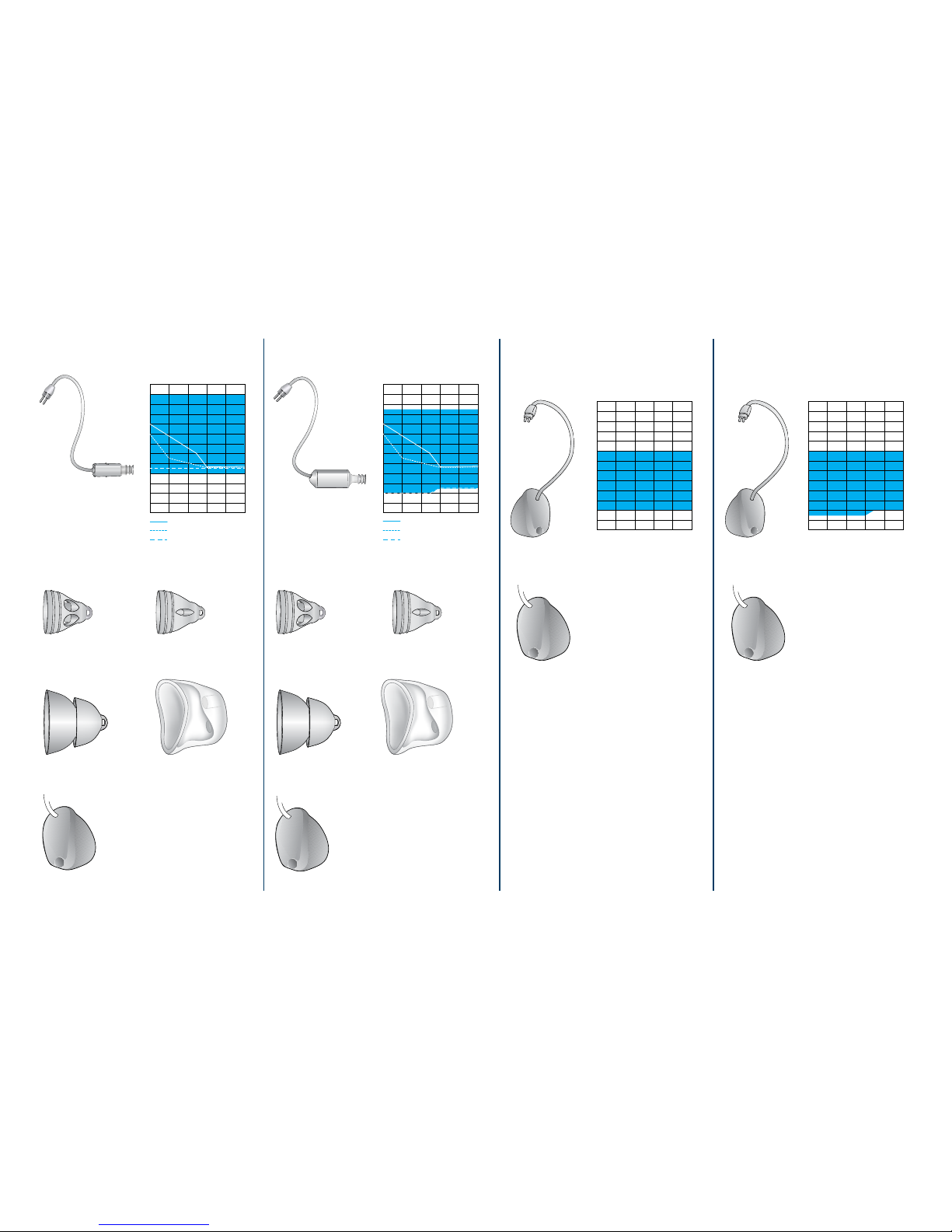
Power dome Power domeSleeve mold Sleeve mold
cShell
cShell
Standard xReceiver
Power xReceiver Super power
xReceiver
Super power plus
*
xReceiver
Coupling options Coupling options Coupling options Coupling options
Open dome Open domeClosed dome Closed dome
cShell cShell
250 500 1000 2000 4000 8000
-10
0
10
20
30
40
50
60
70
80
90
100
110
120
Hz
Open dome
Closed dome
Power dome/sleeve mold
250 500 1000 2000 4000 8000
-10
0
10
20
30
40
50
60
70
80
90
100
110
120
Hz
Open dome
Closed dome
Power dome
*Moxi2 Dura only
Page 4
4
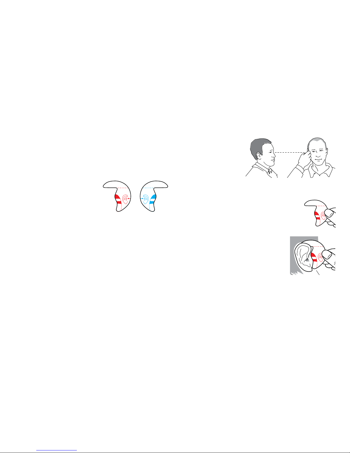
To measure for an accurate wire length:
1. Place your head
at the same
horizontal level as
the patient’s head
so you are looking
straight into the patient’s ear that you wish to t
with the hearing instrument.
2. Hold the measurement tool with the
appropriate blue or red color code
marking (for the le or right ear) with
your thumb placed on the ear diagram.
3. Place the measurement tool on
the top of the ear and in contact
with the skin in the narrow gap
between the head and the pinna.
Keep the horizontal line on the
measurement tool horizontal and level.
Measuring for an accurate
xReceiverunit
Choosing the correct xReceiver wire length will ensure
a more accurate, comfortable t. The measurement
tool included in the kit allows for a quick and simple
measurement and has the
following features:
Color Code Markings – blue
(le ear) and red (right ear)
color code markings to indicate
which of the patient’s ears to measure.
Horizontal Line Markings – measurements must be
made horizontally with the measurement tool touching
the skin in the gap between the head and the top of the
pinna.
Four Horizontal Sightlines – (0-1-2-3) – to indicate which
wire length you should use for an accurate tting.
0
1
2
3
0
1
2
3
0
1
2
3
0
1
2
3
Page 5
5
Modifying xReceiver wire to improve t
In some cases, you might nd that the
wire of the xReceiver unit does not lie
close to the side of the head or follow
the shape of the ear.
First, ensure the selected dome and
xReceiver unit sizes are appropriate
(see following pages).
If a dierent xReceiver tube does not
t better, you may need to modify the
curvature (bend) slightly using the
steps outlined below.
1. Remove the xReceiver unit from the
hearing instrument.
2. Heat the tube carefully with a hairdryer at a low
setting for a few seconds.
3. Do not use excessive heat to avoid damage to the
electrical components.
4. Bend the tubing into the desired shape and hold
until it has cooled o. Once completely cooled, the
tube will maintain its new shape.
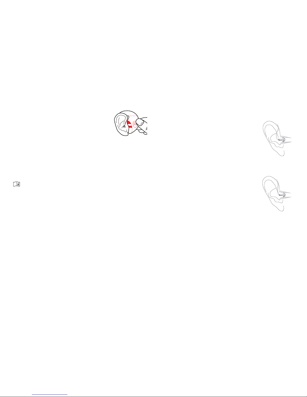
4. Choose the sightline (0-1-2-3) on
the measurement tool that is most
parallel with the top of the opening
of the ear canal. In this example,
the sightline marked 1 would be the most accurate
choice.
5. Make a note of the sightline chosen and then
repeat steps 1-4 on the opposite ear for a binaural
tting.
Note: It is important to measure the opposite ear for a binaural
tting since right and le ear sizes can vary and thus, require
dierent wire lengths.
Poor t
(tube does not lie
close to the head)
Good t
0
1
2
3
Page 6
6
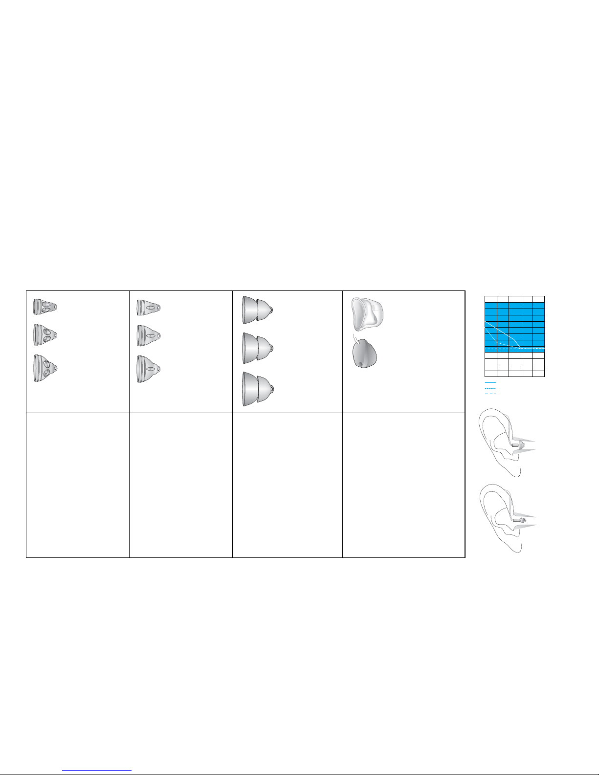
Choosing the correct coupling for standard xReceivers
Determine the correct dome size based on your otoscopic examination of the ear canal.
Selectthedometypebasedon the audiometric requirements and tting ranges shown on this page.
Allowthedome to t comfortably in the ear canal.
Open dome
Choose for:
•Instant t
•Open t
Considerations:
•Occlusion free
Closed dome
Choose for:
•Instant t
•Semi-occluded t
Considerations:
•Extended tting
range over open
dome
•Some occlusion
Power dome
Choose for:
•Instant t
•Occluded t
Considerations:
•Extended low-
frequency response
•Occlusion
Sleeve mold
cShell
Choose for:
•Custom t
•IntelliVent technology
Considerations:
•Comfort
•Possible occlusion
•Impression required
Poor t
(dome too
small)
Good t
250 500 1000 2000 4000 8000
-10
0
10
20
30
40
50
60
70
80
90
100
110
120
Hz
Open dome
Closed dome
Power dome/sleeve mold
Page 7

7
Choosing the correct coupling for power xReceivers
Determine the correct dome size based on your otoscopic examination of the ear canal.
Selectthedometypebasedon the audiometric requirements and tting ranges shown on this page.
Allowthedome to t comfortably in the ear canal.
Open dome
Choose for:
•Instant t
•Open t
Considerations:
•Occlusion free
Closed dome
Choose for:
•Instant t
•Semi-occluded t
Considerations:
•Extended tting
range over open
dome
•Some occlusion
Power dome
Choose for:
•Instant t
•Occluded t
Considerations:
•Extended low-
frequency response
•Occlusion
Sleeve mold
cShell
Choose for:
•Custom t
•IntelliVent technology
Considerations:
•Comfort
•Possible occlusion
•Impression required
250 500 1000 2000 4000 8000
-10
0
10
20
30
40
50
60
70
80
90
100
110
120
Hz
Open dome
Closed dome
Power dome
Page 8

8
Choosing the correct coupling for super power and
super power plus xReceivers
Select,basedon the audiometric requirements and tting ranges shown on this page.
cShell
Choose for:
•Custom t
•IntelliVent technology
Considerations:
•Comfort
•Possible occlusion
•Impression required
250 500 1000 2000 4000 8000
-10
0
10
20
30
40
50
60
70
80
90
100
110
120
Hz
Super power**
xReceiver
**Moxi,2 Moxi2 Kiss only
250 500 1000 2000 4000 8000
-10
0
10
20
30
40
50
60
70
80
90
100
110
120
Hz
Super power plus*
xReceiver
*Moxi2 Dura only
Page 9

9
Attaching the retention piece tothe
standard or power xReceiver unit
The retention piece may be used for ttings with the
open or closed dome depending on the patient’s
requirements. The retention piece is optional and
allows for extra security in the ear. The retention piece
can easily be cut shorter to comfortably t into the
patient’s concha bowl.
To attach the retention piece
1. Slide the retention piece over the receiver.
2. The retention piece should be secured over the
receiver so it appears as one piece.
Page 10

10
Attaching the dome or sleeve mold
to the standard xReceiver unit
1. Hold the xReceiver unit in one hand and the
coupling (i.e. dome or sleeve mold) in the other
hand.
2. Slide the appropriate coupling over the receiver.
3. The xReceiver unit and coupling should t snugly
together.
Attaching the power dome to the
power xReceiver unit
1. Hold the xReceiver unit in one hand and the power
dome in the other hand.
2. Slide the power dome over the receiver.
3. The xReceiver unit and power dome should t
snugly together.
Page 11

11
Attaching the standard, power
or super power xReceiver unit to
Moxi
2
Kiss
Attaching the xReceiver unit to Moxi2 Kiss
1. Use the small silver tool to push the slider pin
slightly sideways.
2. Place the xReceiver unit on Moxi
2
Kiss.
3. Use the back of the small silver tool to push in the
slider pin.
Removing the xReceiver unit from Moxi2 Kiss
1. Use the small silver tool to push the slider pin
slightly sideways.
2. Remove the xReceiver unit.
Page 12

12
Attaching the standard, power or
super power plus xReceiver unit to
Moxi
2
Dura
Attaching the xReceiver unit to Moxi2 Dura
1. Ensure the xReceiver lock is in the open position.
2. Place the xReceiver unit on the hearing aid.
3. Push the lock closed.
Replacing the xReceiver unit from Moxi
2
Dura
1. Insert the tool into the slot to open the xReceiver lock.
2. Remove the xReceiver unit
Attaching the standard, power or
super power xReceiver unit to Moxi
2
Attaching the xReceiver unit to Moxi
2
1. Place the xReceiver unit on Moxi.
2
2. Place the pin in the hole.
3. Use the back of the small silver tool to push in the pin.
Removing the xReceiver unit from Moxi
2
1. Use the small silver tool to push the pin out.
2. Remove the xReceiver unit.
Page 13

13
Conguring in Unitron TrueFit
soware
Detection screen
1. Connect hearing instrument to the NOAHLink,
HI-PRO, or iCube and click the detect icon. Unitron
TrueFit
™
soware will display the connected devices
and serial numbers.
Note: Aer connecting to the hearing devices, go to the
Acoustics screen and select the correct receiver and “tip”
option.
Acoustics screen
2. Go to the Acoustics screen in the Instruments
menu.
3. Select the connected Receiver unit for each hearing
instrument from the drop-down lists.
4. Select the connected tip from the drop down list. If
applicable, choose the appropriate size of venting.
5. If custom shell is selected and has the IntelliVent
technology, enter the IntelliVent code for optimal
venting acoustics. The IntelliVent coupling code is
inscribed on the custom shell.
Whenever a change to the xReceiver unit or dome
is made during the tting, you need to revisit the
Acoustics screen and specify your choices to allow for
correct gain calculations.
Note: Please ensure that the connected xReceiver unit is
selected and a QuickFit is performed before inserting hearing
instrument into your patient’s ear canal.
Once your setup selection is complete, go to Feedback
Optimization under Fitting.
Page 14

14
Feedback optimization
Run Feedback Optimization.
Appendix
Using the Moxi2 shell removal tool
The shell removal tool is used to remove the top shell
from Moxi
2
to access the microphone protector.
Note: Moxi
2
Kiss and Moxi Dura models do not have a
replaceable microphone protector. It is not necessary to
remove the shell.
Removing the top shell of Moxi
2
1. Open the battery door and insert the tool on a slight
angle, inserting one pin on the side of the tool with
the notch inside the battery compartment.
2. Twist the tool down in the opposite direction to
snap the tool into place.
3. Squeeze the tool in the center to push the shell out
of the notches.
4. Li the shell up and forward o the hearing
instrument and over the push button. This allows
access to the microphone protector.
Page 15

15
Replacing the top shell
1. Position the top shell over the push button on the
hearing instrument.
2. Then push the shell down and back until it snaps
into place.
Microphone protector replacement
The microphone protector prevents moisture and
debris damage to the microphone. A clogged
microphone protector could aect the performance of
the hearing device. If this occurs, the mic protector can
be easily replaced.
Removal
1. Aer removing the top shell (shown on previous
page), remove the microphone protector with a
tweezer.
Installation
1. Place the new mic protector with a tweezer.
2. Smooth down the mic protector with your nger.
3. Replace the top shell.
Page 16

16
Moxi2 Kiss battery door replacement
Removal
1. Use the small silver tool to push the pin out.
2. Remove the battery door.
Installation
1. Line up the battery door.
2. Insert the pin. Use the back of the small silver tool
to push the pin in.
Moxi2 Dura battery door replacement
Removal
1. Use the small silver tool to push the pin out.
2. Remove the battery door.
Installation
1. Line up the battery door.
2. Insert the pin. Use the back of the small silver tool
to push the pin in.
Page 17

17
Moxi2 battery door replacement
Removal
1. Use the small silver tool to push the pin out.
2. Remove the battery door.
Installation
1. Line up the battery door.
2. Insert the pin. Use the back of the small silver tool
to push the pin in.
How to measure performance in a coupler
RIC devices should be measured with a HA1 coupler
since it best reflects the acoustical properties in the ear
canal.
The xReceiver kit includes a metal adapter plate that
ts on a HA1 coupler and allows for a good connection
of the xReceiver unit to the coupler.
Select Activate Test Box Measurement Mode in
Unitron TrueFit soware from the menu on the top
menu bar. Clicking on Activate Test Box Measurement
Mode disables the adaptive features and activates
the omnidirectional microphone mode to allow for
correct measurements. Click on Deactivate Test Box
Measurement Mode to reestablish the previous
settings.
Attach the standard xReceiver to the metal adapter plate.
Page 18

18
Moxi2 Kiss programming cable
Insertion
1. Open the battery door to reveal the programming
port.
2. Push the cable down onto the programming port.
Removal
1. Pull up on the programming cable and remove.
Moxi2 Dura programming cable
Insertion
1. Open the battery door to reveal the programming
port.
2. Push the cable down onto the programming port.
Removal
1. Pull up on the programming cable and remove.
Page 19

19
Moxi2 programming cable
Insertion
(The optional programming tool can be used for
support during the installation.)
1. Place the optional programming tool over the
programming cable and slide it up over the top of
the cable.
2. Insert the programming cable into the battery
compartment.
3. Push down on the programming cable.
Removal
1. Push up on the programming cable.
2. Remove the cable.
Wax guard replacement and cleaning domes
All xReceiver units are equipped with a wax guard
system to protect the xReceiver from ear wax. The wax
guard can be easily replaced. You will need to counsel
your patient on how to replace the wax protector, see
instructions included with the replacement packs.
If necessary, the domes and xReceiver units can be
wiped with a damp cloth; however, xReceiver units
should never be submerged in water to avoid damage
to the electrical components.
Page 20

Australia - 1800 212 313
Belgium - +32 (0) 2 468 19 81
Canada - 1 800 265 8255
China - 512 6258 2258
Colombia - 57 1214 9847
Denmark - +45 3832 1229
European Representative &
Germany - +49 711 658538 0
France - 0821 02 9000
India - +91-22-26871151
International - +1 519 895 0100
Netherlands - +31 88 600 88 10
New Zealand - 0800 864 8766
Norway - +47 23 00 32 70
Russia - +7 495 788 02 04
South Africa - (011) 467 7662/52
South Korea - +82 10 3414 8366
Spain - +34 902 494 960
Sweden - +46 (0) 8 546 20 960
Switzerland - 0800 928 801
U.K. - 01925 247810
U.S. - 1 800 888 8882
20 Beasley Drive, P.O. Box 9017,
Kitchener, ON N2G 4X1 Canada
13-026 029-5936-02
At Unitron, we care deeply about people with hearing loss. We work closely
with hearing healthcare professionals to provide hearing solutions that
improve lives in meaningful ways. Because hearing matters.
unitron.com
Contact us
 Loading...