

Page 1
User Manual
UNIVERSE
Ref. 8600
Page 2

UNIVERSE (REF. 8600)
2
No part of this manual may be copied, reproduced, transmitted, transcribed or translated into any
language without permission.
Unitron reserves the right to change the specifications of the hardware and software described in these
manuals at any time.
Unitron cannot be held liable for any damages resulting from the use of this product.
Specifications are subject to change without notice. 09/15
© Unitron - Frankrijklaan 27 - B-8970 Poperinge - Belgium
T +32 57 33 33 63 F +32 57 33 45 24
email sales@johansson.be
www.johansson.be - www.unitrongroup.com
Page 3

UNIVERSE (REF. 8600)
3
CONTENTS
1. INTRODUCTION ............................................................................... 4
Product description ............................................................................................. 4
Package contents ............................................................................................... 4
Mounting ........................................................................................................... 4
Typical installation .............................................................................................. 5
Safety Instructions ............................................................................................. 7
2. INSTALLATION OF THE HARDWARE ....................................................... 8
Module overview ................................................................................................ 8
Connecting the power supply ............................................................................... 9
3. CONFIGURATION OF THE MODULE ...................................................... 10
3.1. Minimal system requirements................................................................... 10
3.2. Starting up the module ........................................................................... 10
3.2.1. Device Information ...................................................................... 12
3.2.2. Device Configuration ................................................................... 12
Login .............................................................................................. 12
Network .......................................................................................... 13
Firmware Update .............................................................................. 13
Reboot ............................................................................................ 13
3.2.3. Input Settings ............................................................................ 14
LNB / Multiswitch .............................................................................. 14
Single Cable (EN 50494) and (EN 50607) ............................................ 15
DC for Terrestrial Amp. ..................................................................... 15
3.2.4 CAM ........................................................................................... 18
3.2.5 Output Settings ........................................................................... 19
IP ................................................................................................... 19
RF .................................................................................................. 21
3.3. Import and export settings ...................................................................... 24
4 TECHNICAL SPECIFICATIONS ............................................................ 25
5 CONDITIONS OF WARRANTY ............................................................. 27
Page 4
UNIVERSE (REF. 8600)
4
1. INTRODUCTION
Product description
Receives 1 transponder from any DVB source (satellite, terrestrial or cable)
Decrypts the PayTV channels, when a professional CAM is inserted
Puts the demodulated transponder on your private coaxial and IP network
Can work standalone to insert channels in your existing network
More products can be combined to a make a complete headend:
Cascadable inputs and outputs
Remote powering capabilities
Compatible with SD and HD, with MPEG2 and MPEG4
Perfect picture quality thanks to a MER, comparable to premium headend equipment
Plug&Play thanks to a built-in WebGUI
Package contents
1x Universe (ref.8600)
1x Power adaptor (including mounting plate with tie-wrap)
1x Ethernet cable
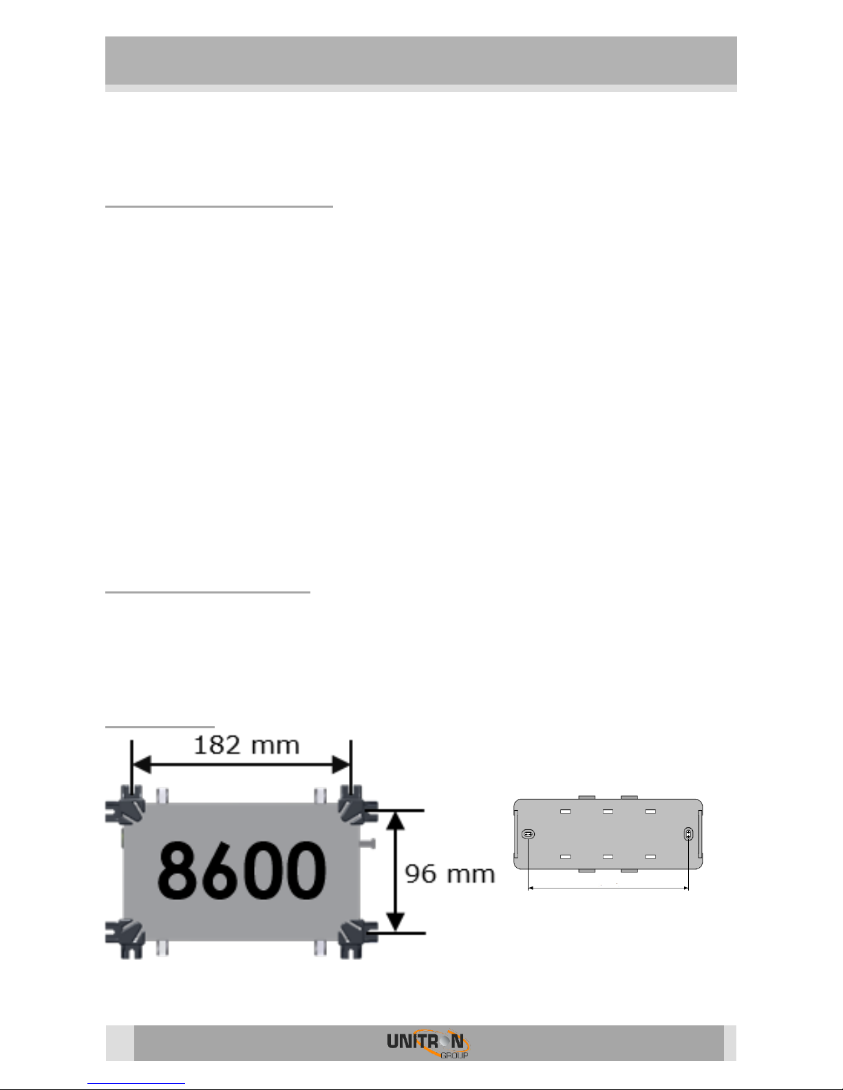
Mounting
149 mm
Mounting plate
Page 5
UNIVERSE (REF. 8600)
5
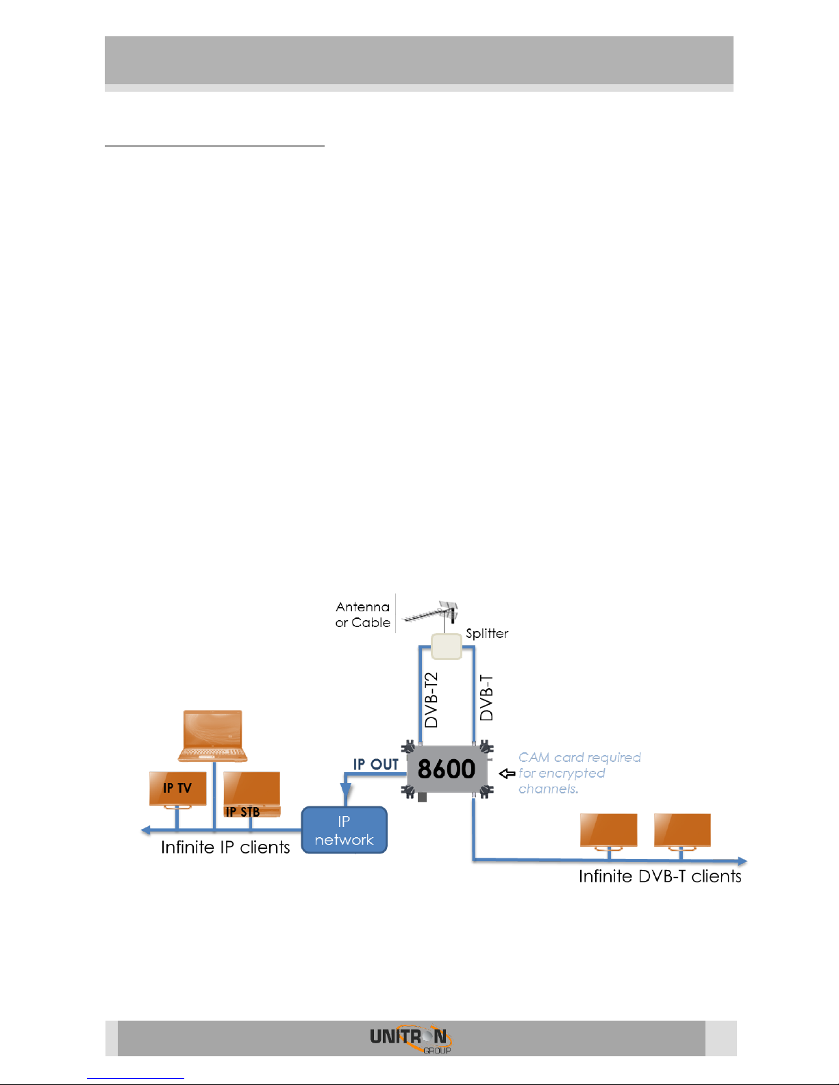
Typical installation
Perfect when your TV installation does not have satellite tuners, but you wish to receive
satellite TV.
Perfect when your TV installation does not support DVB-T2 tuners, but you wish to
receive the newest DVB-T2 signals. See figure 1.
In existing installation where you want to add a few extra channels from different
sources.
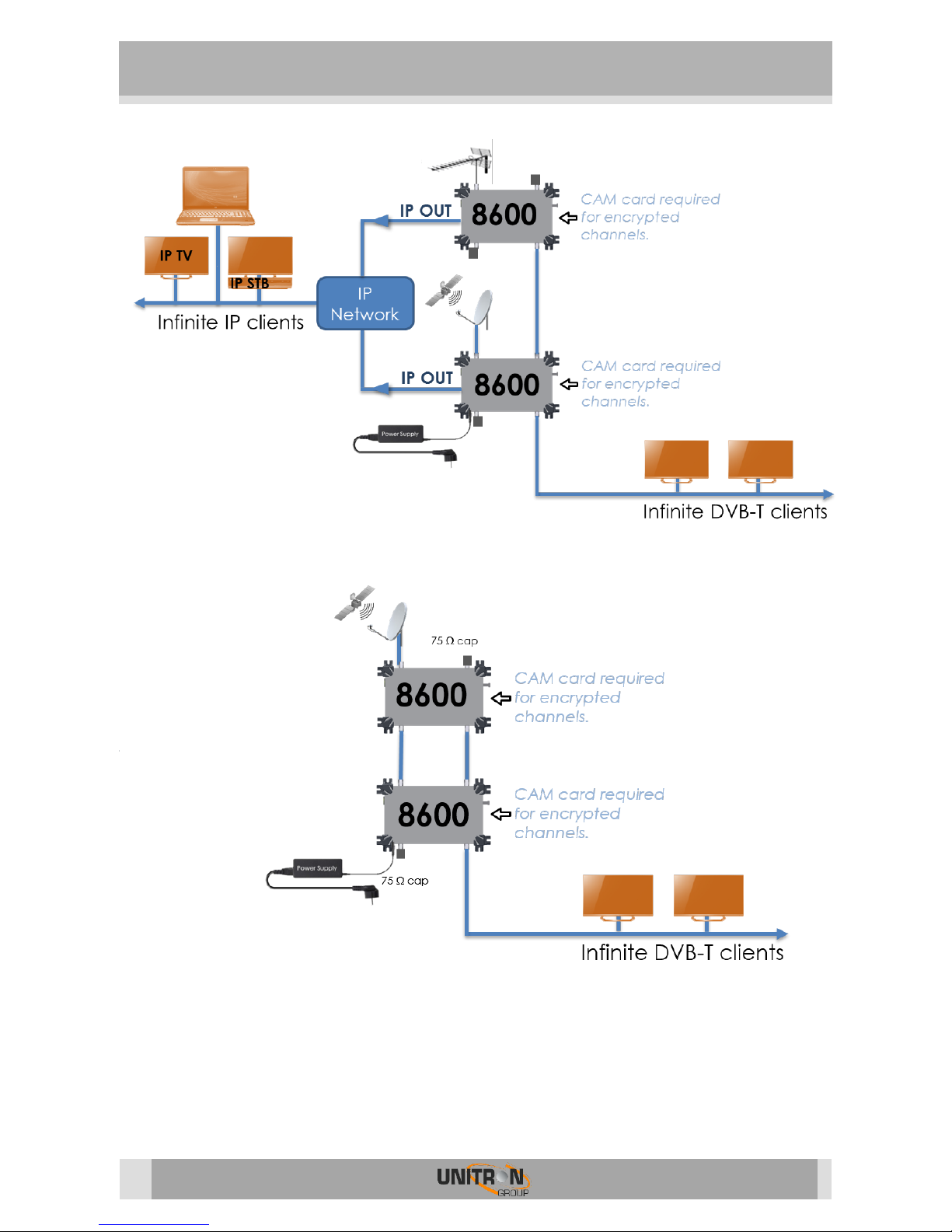
New installations, where you can use 1 or multiple Universes to setup a complete
network of TV and radio channels. See figures 2 and 3.
In some countries, the operator does not support CAMs with business-to-business (B2B)
subscriptions. But if that operator allows professional installations, you can use multiple
Universes with business-to-consumer (B2C) subscriptions without driving the costs too
high.
FIGURE 1: DVB-T2 CONVERTED TO DVB-T SIGNALS AND ADDED TO THE DVB-T BROADCAST
75 cap
Page 6
UNIVERSE (REF. 8600)
6
FIGURE 2: DVB-T AND DVB-S2 CONVERTED TO DVB-T AND IP CHANNELS
FIGURE 3: DVB-S2 CONVERTED TO DVB-T
75 cap
75 cap
75 cap
Page 7
UNIVERSE (REF. 8600)
7
Safety Instructions
Read these instructions carefully before connecting the unit
To prevent fire, short circuit or shock
hazard:
Do not expose the unit to rain or moisture.
Install the unit in a dry location without infiltration or condensation of water.
Do not expose it to dripping or splashing.
Do not place objects filled with liquids, such as vases, on the apparatus.
If any liquid should accidentally fall into the cabinet, disconnect the power plug.
To avoid any risk of
overheating:
Install the unit in a well aired location and keep a minimum distance of 15 cm around the
apparatus for sufficient ventilation
Do not place any items such as newspapers, table-cloths, curtains,
on the unit that might cover the ventilation holes.
Do not place any naked flame sources, such as lighted candles, on the apparatus
Do not install the product in a dusty place
Use the apparatus only in moderate climates (not in tropical climates)
Respect the minimum and maximum temperature specifications
To avoid any risk of electrical
shocks:
Connect apparatus only to socket with protective earth connection.
The mains plug shall remain readily operable
Pull out power plug to make the different connections of cables
To avoid electrical shock, do not open the housing of adapter.
Maintenance
Only use a dry soft cloth to clean the
cabinet.
Do not use solvent
For repairing and servicing refer to qualified
personnel.
Dispose according your local authority’s recycling processes
Page 8
UNIVERSE (REF. 8600)
8
2. INSTALLATION OF THE HARDWARE
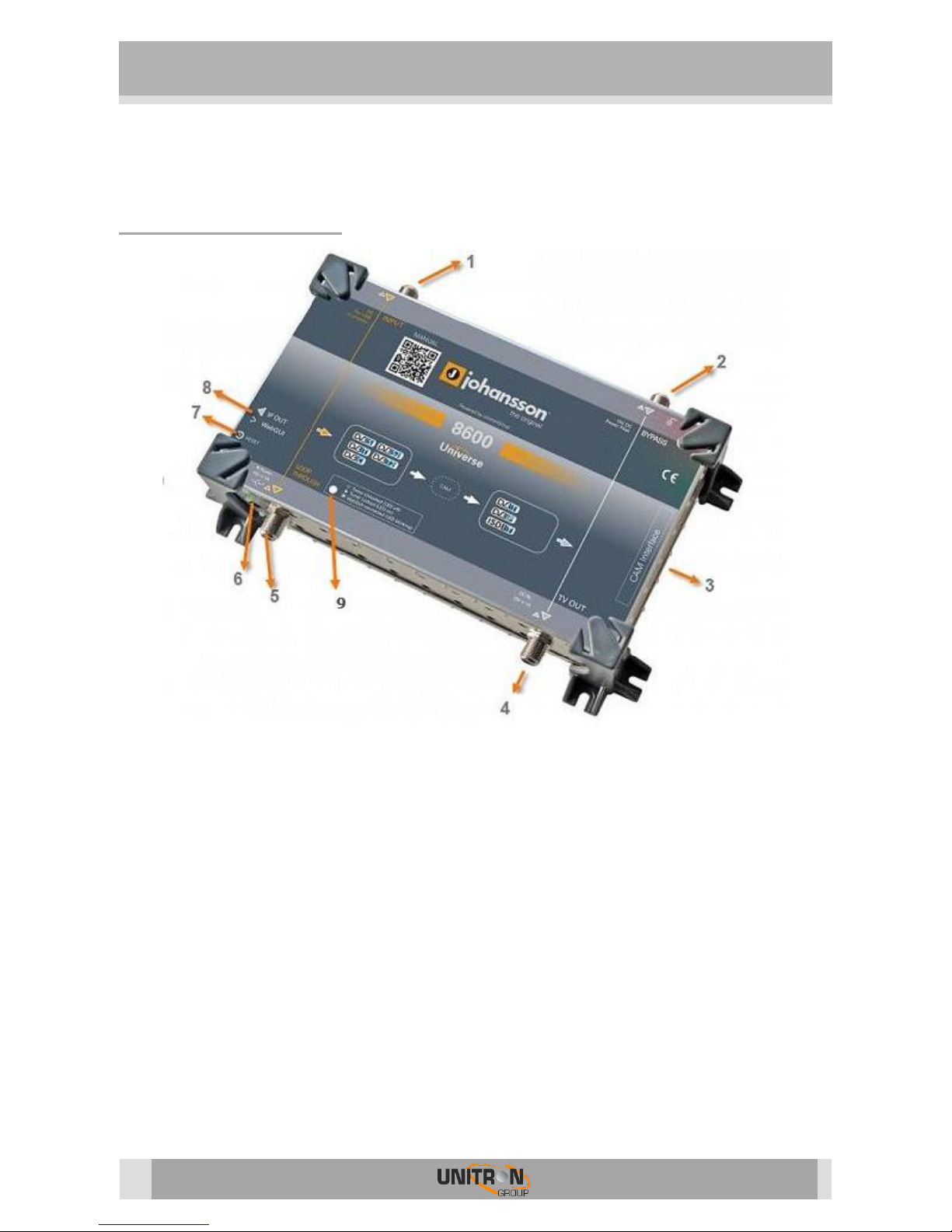
Module overview
1. INPUT: DVB-S/S2, DVB-T/T2, DVB-C
2. BYPASS: to insert a network of existing TV channels (should be blocked with a 75 DC-
blocked resistor when not used)
3. CAM INTERFACE
4. TV OUT: DVB-T or ISDB-T
5. LOOP-THROUGH: to connect to the next Universe INPUT (should be blocked with a 75
DC-blocked resistor when not used)
6. 15 VDC INPUT + POWER LED
7. RESET BUTTON
8. ETHERNET CONNECTOR: WebGUI + IP OUT
9. TUNER LOCK LED: indicates if the tuner is locked. If the LED is blinking, that means the
WebGUI is connected.
For typical applications, see figure 1, 2 and 3 on page 5 and next.
Page 9

UNIVERSE (REF. 8600)
9
Connecting the power supply
The Universe works with the supplied adaptor of 15V DC. The power supply can be connected
via the inlet (6) but the Universe can also be powered via the TV OUT (4).
15V DC is also being supplied to the BYPASS (2), which enables 1 power supply to feed more
than 1 unit. Up to 3 Universes can be powered from the same adaptor.
Page 10

UNIVERSE (REF. 8600)
10
3. CONFIGURATION OF THE MODULE
3.1. Minimal system requirements
The WebGUI is supported by the following web browsers (and newer versions of these
browsers):
Chrome 4
Safari 3.1
Firefox 3.6
Explorer 9
Opera 10.6
When using a different browser, we cannot guarantee a correct functioning of the interface.
3.2. Starting up the module
Connect all cables needed for your installation. (See p.8 Installation of the Hardware.)
For the first set-up it is advised to connect the Ethernet cable (RJ45) directly to your PC
(without using a switch).
After powering the Universe, wait until the power led turns green (this can take about 2
minutes). Once the power led is green, the unit can be accessed through the WebGUI.
The unit uses 192.168.50.50 as the default IP address. Therefore, you will need to set-
up a static IP in your PC that matches the
subnet of the device. For example
192.168.50.25.
Windows 7
Go to start Control Panel Network and
Internet Network and Sharing Center
Change Adapter Settings.
Right-click on “Local Area Connection” and
then on “Properties”.
Windows 8
Open the windows 8 start screen by pressing
the start button. Type “Control Panel” and
press enter. Then go to “Network and Internet”
“Network and Sharing Center” “Change
Adapter Settings”. Right-click on “Local Area
Connection” and then on “Properties”.
Double click on “Internet Protocol Version 4
(TCP/IPv4)” to enter the IP settings of your
adaptor.
Page 11

UNIVERSE (REF. 8600)
11
Check the radio button “Use the following IP
address” and enter an IP and subnet mask.
You can leave the Default gateway and DNS
settings empty.
Open your browser and surf to the website http://192.168.50.50.
If everything went fine you will see the following webpage, if not check your network settings
and try again.
After you have changed the IP address of your device (See page 12) you can unplug the direct
cable and add the device to your installation. Don’t forget to change the IP settings of your PC
back to its previous settings.
Resetting the device
Reboot the device by shortly pressing the reset button 1 second. When the button is released
the power led will turn red until the device is rebooted.
Reset the device to factory default settings by pressing the reset button for more than 10
seconds. When the button is released the power led will turn red until the reset is done. The
device will be restored to factory default settings and the IP of the device will be changed to
192.168.50.50.
Page 12
UNIVERSE (REF. 8600)
12
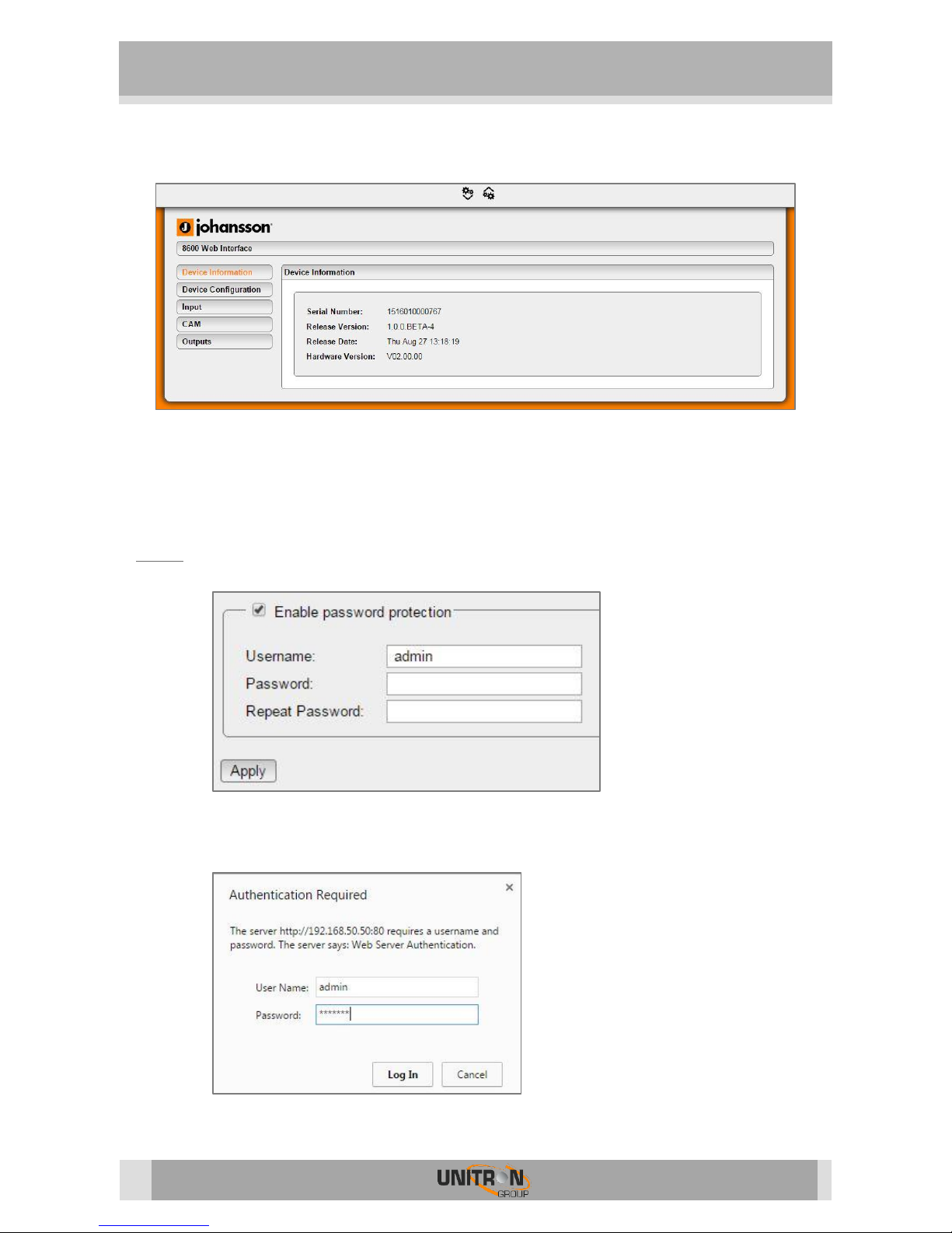
3.2.1. Device Information
Device Information gives some basic information about the device. Here you can find the serial
number, firmware version, the release date of the firmware and the hardware version. This is
useful for checking if your device is up-to-date.
3.2.2. Device Configuration
Login
Here you can set up a user and password to secure the WebGUI. After pressing the “Apply”
button you will be asked to reboot the device. Press “OK” to confirm the reboot.
The next time you want to access the
configuration pages you will be asked
to login. The device information page
remains accessible without
authenticating.
If you have forgotten your password
you will need to reset the Universe to
its default settings by pressing the
reset button (see p. 11).
Page 13
UNIVERSE (REF. 8600)
13
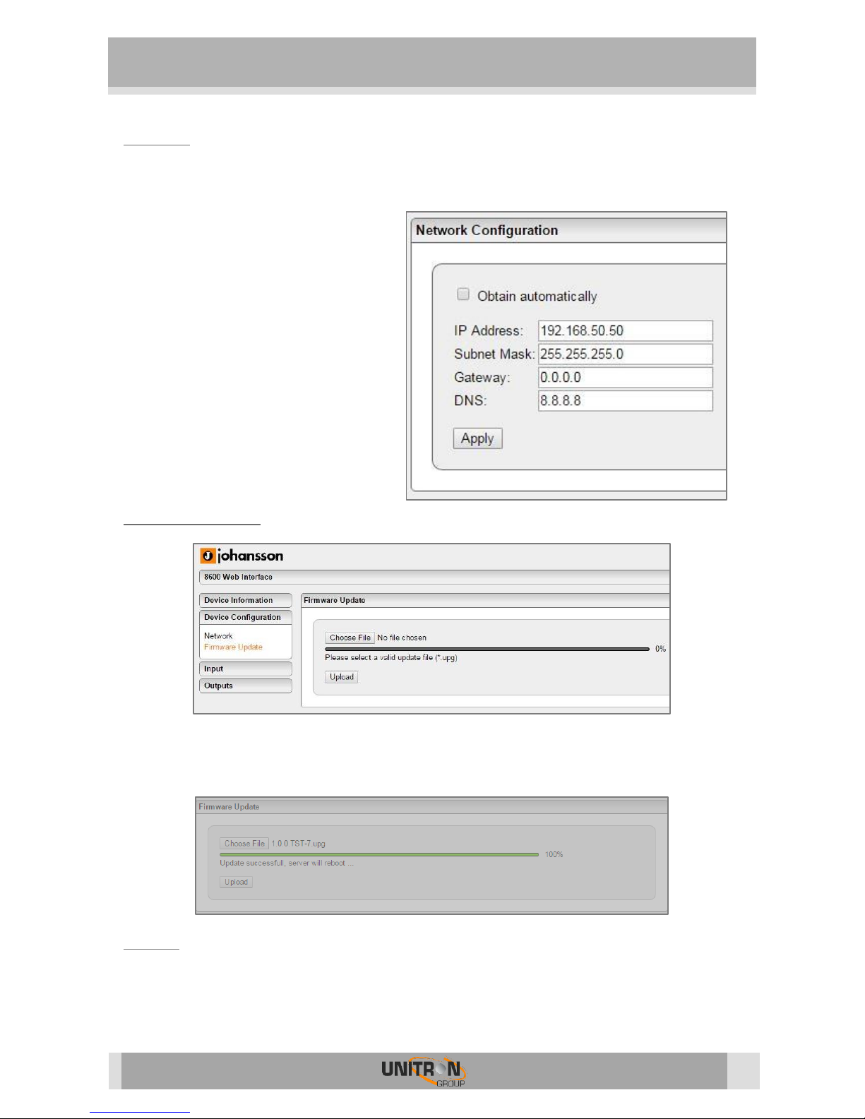
Network
Go to “Device Configuration” “Network” to change your IP settings. After changing the IP
settings you will need to reconnect to the new IP.
You can choose to obtain an IP address
automatically. This requires a DHCP
server, which is available on most home
and professional IP networks. You can
find the IP address of your device in the
DHCP client list of your DHCP server.
Alternatively, you can keep the Universe
in static IP 192.168.50.50 or any other
address of your choice.
Remark: The “Apply” button starts
blinking if you change the settings of the
Universe so you won’t forget to press it.
Firmware Update
If you want to update the firmware click on “Choose File” and select the update file. The
firmware file ends with the *.upg extension. Then click the “Upload” button and wait until the
file is uploaded and the device is rebooted.
Reboot
Click on “Reboot” to restart your device. This is useful when you don’t have physical access to
the Universe.
Page 14

UNIVERSE (REF. 8600)
14
3.2.3. Input Settings
Choose the mode you want to use and if required the type of LNB. The following settings
depends on the Mode and LNB used. If you select the Universal or C-Band LNB the LO
Frequency and Band / Tone settings will not be shown because those settings are filled in
automatically.
LNB / Multiswitch
Choose this mode if you are using a regular LNB or a multiswitch.
LO Frequency (kHz): The LO Frequency used in the LNB. Set this to 0 when intermediate
frequencies (IF) are used for tuning. This setting will be filled in automatically when
choosing the Universal or C-Band LNB type. (only available if LNB type is manual)
The LNB / Multiswitch is being controlled by another device: Enable this setting if you are
using another device to control the input e.g. another universe.
Polarisation / Voltage: The polarisation or voltage you want to use.
Band / Tone: The band / tone you want to use. (only available if LNB type is manual)
Sat.: The satellite (A, B, C, D) used.
Apply: Save your current settings!
Page 15

UNIVERSE (REF. 8600)
15
Single Cable (EN 50494) and (EN 50607)
LO Frequency (kHz): The LO Frequency used in the LNB. Set this to 0 when intermediate
frequencies (IF) are used for tuning. This setting will be filled in automatically when
choosing the Universal or C-Band LNB type. (only available if LNB type is manual)
User Band (UB)*: The user band you want to receive.
UB Frequency (kHz)*: The user band frequency.
Polarisation / Voltage: The polarisation or voltage you want to use.
Band / Tone: The band / tone you want to use. (only available if LNB type is manual)
Sat.: The satellite (A, B, C, D) used.
Apply: Save your current settings!
* : You can find the desired User Band and User Band frequency in the manual of your
SCR LNB or multiswitch
DC for Terrestrial Amp.
The terrestrial amp. is being powered from another device (disable power): Enable this
option if you use another device to power the terrestrial amplifier.
Voltage: Choose the desired voltage 12V or 24V.
Apply: Save your current settings!
Page 16

UNIVERSE (REF. 8600)
16
The LNA/LNB is now configured. Next we will configure the tuner.
Change your input type to the DVB source you are using. Select the frequency and symbol rate
or bandwidth to match the transponder you want to receive and click on “Apply”. To know the
transponder go to http://www.lyngsat.com or http://kingofsat.net. If all settings are correct the
lock icon will turn green.
Lock: Green symbol means the device is locked on the chosen transponder.
Bitrate: The bitrate of the incoming signal.
Level: The level of the incoming signal.
SNR: Signal to Noise Ratio of the incoming signal.
PER: Packet Error Rate of the incoming signal. This should be 0% otherwise the incoming
signal quality is bad.
CAM Inserted: Turns green if a CAM module is detected.
Page 17
UNIVERSE (REF. 8600)
17
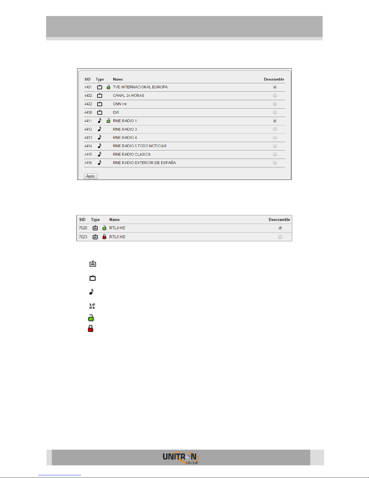
If the tuner is well configured and the lock icon is green the list of channels should be available.
Select the service(s) you want to run through the CAM Interface by checking the Descramble
checkboxes. A red lock means the service is encrypted and a green one means the service runs
through the CAM module and can now be decrypted. Confirm with the “Apply” button.
SID: Service ID for listed service.
Type: : HD-TV
: SD-TV
: Radio
: Data
Lock: : Descrambled service.
: Scrambled service.
No lock: FTA service.
Name: Name of the service.
Descramble: Determines if the selected service goes through the CAM or not.
Page 18

UNIVERSE (REF. 8600)
18
3.2.4 CAM
The CAM menu will open automatically in a few seconds, if it doesn’t you can click the
“(Re)open CAM Menu” button. To use the CAM menu click on the menu item you want to open
and click on “Return” to go back 1 step in the menu.
The CAM menu will be different if you use another CAM module and/or CAM card. For more
information about the CAM menus refer to its specific manual.
If you get the message “Waiting for smart card, please wait” you will need to wait a few
seconds and then click the “(Re)open CAM Menu” button or the “Waiting for smart card”
message to refresh the menu.
Page 19

UNIVERSE (REF. 8600)
19
3.2.5 Output Settings
IP
Click on “Add Service” to add a service to an IP stream. You can keep adding services until the
CPU hits 100%. But if the CPU usage exceeds 90% you can have performance issues, due to
peaks in the services. If you want the Universe to decrypt the services, make sure the lock icon
is green otherwise go back to input settings and descramble the service.
Don’t forget to press the “Apply” button when all output settings are done.
SID: Service ID.
Type: : HD-TV
: SD-TV
: Radio
: Data
Lock: : Descrambled service.
: Scrambled service.
No lock: FTA service.
Name: Name of the service.
Dest. Address: Destination address, the IP address the service will run on, needs to be in
the 239.0.0.0-239.255.255.255 range.
Dest. Port: Destination port, the port the service will run on.
! Make sure that no 2 service(s) have the same Destination address and Destination
port, in that case only 1 service will be available.
Page 20

UNIVERSE (REF. 8600)
20
Enabled: Turns the service on or off. Can be used instead of the delete button if you are
planning to use that service later.
Delete button: Deletes the service from the list.
Details: Show advanced settings about the service, see details below.
Apply: Saves the current settings!
Click “Download playlist: ” to download a playlist for your streams. This playlist can be
opened on your computer with VLC or can be imported in your IPTV setup box or middleware.
Click on “Details” to enter the advanced settings for that service. Here you can enable or disable
the underlying streams. Don’t forget to press the “Apply” button.
PID: Package identifier for the listed stream.
Type: : Video
: Audio
: Data
Bitrate: Bitrate of the stream.
Enabled: Turns the selected stream on or off.
Page 21

UNIVERSE (REF. 8600)
21
RF
In the RF Output section, the Universe has to be configured differently than the IP Output.
While in the IP section, you add services to your list, in the RF section you have to disable
services till you have no longer an overflow. The reason is that for instance a 55Mbps satellite
transponder will not fit in a DVB-T MUX of 32 Mbps.
Don’t forget to press the “Apply” button after the configuration is done.
Type: Type of output signal.
Frequency (kHz): Here you can select the frequency you want to transmit on.
Bandwidth: Choose the desired bandwidth.
Constellation: Choose the type of constellation you want to use. (64QAM, 16QAM, QPSK)
Code Rate: The following code rates can be used 7/8, 5/6, 3/4, 2/3 or 1/2. A higher code
rate means more services can be selected without having an overflow.
Guard Interval: The following code rates can be used 1/32, 1/16, 1/8 or 1/4.
Mode: 2k, 4k or 8k.
Attenuation (dB): Enter a value between 0 and 45 dB, 0dB being the maximum output
power.
State: Turns the output on or off.
Bitrate: Total bitrate that is being output at the TV OUT connector. Turns red if you have
an overflow.
Overflow: Turns red if too many services are selected. Please uncheck some services or
streams and click apply until the symbol turns grey, and the Bitrate turns green.
PID Filter: Shows the amount of PIDs you can still filter out. The Universe can disable up
to 27 PIDs.
Page 22

UNIVERSE (REF. 8600)
22
SID: Service ID.
Type: : HD-TV
: SD-TV
: Radio
: Data
Lock: : Descrambled service.
: Scrambled service.
No lock: FTA service.
Name: Name of the service.
Enabled: Add the service to the RF output. If you disable a video service only the video
stream will be disabled, see remark below.
Details: Show advanced settings about the service.
Apply: Save the current service list.
Remark: If you disable a SID only the main PID and SID will be disabled. All smaller
underlying PIDs (data, audio services) will remain active. The audio will keep running
until you rescan your TV. For disabling specific underlying PIDs please go to “Details”.
Remark: The order of the channels will be determined by your receiver. It is advised to set
the country to “Others” when scanning the receiver for channels. You can always use the
channel numbering function of your receiver if you want to change the order of the
channels.
Page 23

UNIVERSE (REF. 8600)
23
Click on details to enter the advanced settings for that service. Here you can enable or disable
the underlying streams. Don’t forget to press the “Apply” button.
PID: Package identifier.
Type: : Video
: Audio
: Data
Bitrate: Bitrate of the stream.
Enabled: Turns the selected stream on or off.
Remark: A lot of transponders use shared PIDs. That means that 2 or more services make
use of the same stream. In that case, when disabling that shared PID, the Universe will
warn you about all the services that will be influenced by disabling that shared stream.
Click “OK” to continue or click on “Cancel” if you don’t want those services to be affected.
Page 24

UNIVERSE (REF. 8600)
24
Disabling SIDs vs disabling PIDs.
If you disable all PIDs but let the covering SID enabled your receiver will still find the service
but there will be no image or sound. This can be used if you temporary want to disable a service
but don’t want to rescan your receiver.
If you enable all PIDs and disable the covering SID, the PIDs will remain active and consume
bandwidth but your receiver won’t find it when you do a rescan. So if you want to save
bandwidth you better disable the underlying PIDs starting with the one that has the biggest
bitrate as the amount of PIDs that can be filtered is limited.
3.3. Import and export settings
: Click on this button to import your settings from the same or another Universe.
: Click on this button to export your setting to a configuration file. You can import this
configuration file in another Universe or to store your configuration on your pc.
Page 25

UNIVERSE (REF. 8600)
25
4 TECHNICAL SPECIFICATIONS
8600 – Universe
INPUT
Number of inputs
-
1 with passive loop-through (-2dB)
Tuner - 1
Frequency Range
MHz
42 – 2150
Input level
dBm
-65 to -20
Standard
-
DVB-S/S2
DVB-T/T2
DVB-C
DC remote power for LNB or LNA
V
0/13/18/22kHz
DiSEqC, EN50494, EN50607
350
-
mA
RF OUTPUT
Number of outputs
-
1 RF with passive loop-through (-2 dB)
Multiplex
-
1
Frequency range
MHz
174-862
Output level
dBm
-55 to -10 (adjustable)
Standard
-
DVB-T
ISDB-T*
Modulation error rate (MER)
dB
40
ETHERNET OUTPUT
Number of outputs
-
1Gb Ethernet
Standard
-
IEEE 203ab 10/100/1000 Base-T
Protocol
-
Multicast IP/UDP
* Coming soon
Page 26

UNIVERSE (REF. 8600)
26
GENERAL
CI slot - 1
Input voltage
VDC
12-20
Power consumption
W
7 (without CAM and without remote power)
DC jack
mm
Ø 2.1
Powering remote units
-
Yes, 1 unit can power other units
Operating temperature
°C
0-50
Dimensions
mm
222x142x50
Weight
kg
1.1
Accessories
-
15V power adapter, 1 Ethernet cable
Page 27

UNIVERSE (REF. 8600)
27
5 CONDITIONS OF WARRANTY
Unitron N.V. warrants the product as being free from defects in material and
workmanship for a period of 24 months starting from the date of production indicated on
it. See note below.
If during this period of warranty the product proves defective, under normal use, due to
defective materials or workmanship, Unitron N.V, at its sole option, will repair or replace the
product. Return the product to your local dealer for reparation
THE WARRANTY IS APPLIED ONLY FOR DEFECTS IN MATERIAL AND WORKMANSHIP
AND DOES NOT COVER DAMAGE RESULTING FROM:
Misuse or use of the product out of its specifications.
Installation or use in a manner inconsistent with the technical or safety standards in
force in the country where the product is used
Use of non-suitable accessories (power supply, adapters...).
Installation in a defect system.
External cause beyond the control of Unitron N.V. such as drop, accidents,
lightning, water, fire, improper ventilation…
THE WARRANTY IS NOT APPLIED IF
Production date or serial number on the product is illegible, altered, deleted or removed.
The product has been opened or repaired by a non-authorized person.
NOTE
Date of production is YYWW format, example 1527 = year 2015 – week 27.
For the serial number barcodes, the date corresponds to the 4 first numbers
Page 28
UNIVERSE (REF. 8600)
28
UNITRON NV
Frankrijklaan 27
B-8970 Poperinge
Belgium
T +32 57 33 33 63
F +32 57 33 45 24
sales@johansson.be
www.johansson.be
 Loading...