

Page 1
UserManual
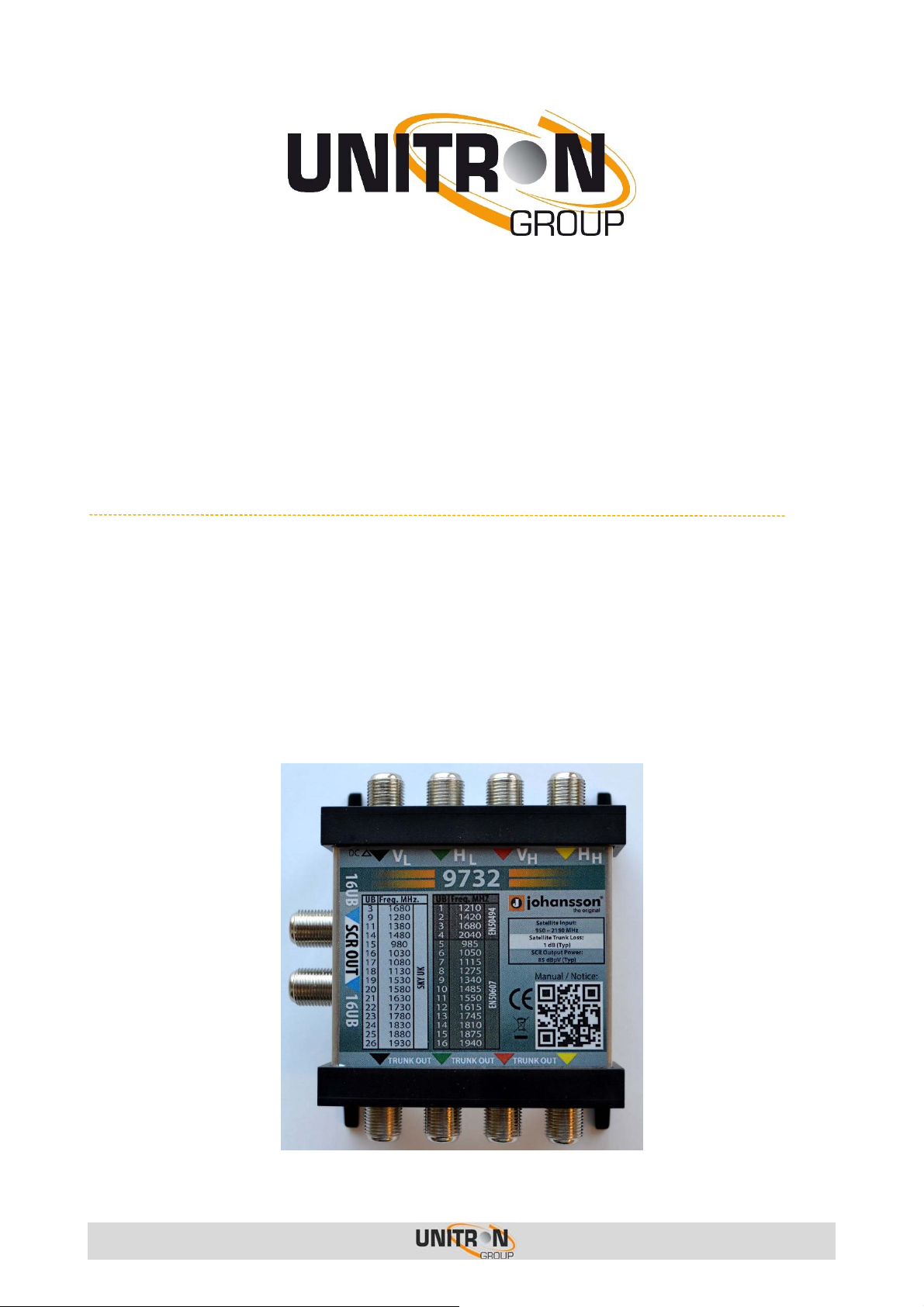
dCSS/dSCR Multiswitch
9732
Page 2

dCSS/dSCR Multiswitch (Ref. 9732) v1.0
CONTENTS
1. I
NSTALLATION OF THE HARDWARE
...................................................... 3
2. C
ONFIGURATION OF THE MODULE
Installation Mode .............................................................................................. 4
CSS Mode ....................................................................................................... 4
3. T
4. S
5. C
ONLY EN50494/SCR standard ................................................................... 4
ONLY EN50607/dCSS standard ................................................................. 4
CONCURRENT EN50494/EN50607 standards ............................................... 4
SKY UK standard .................................................................................... 4
ECHNICAL SPECIFICATIONS
AFETY INSTRUCTIONS
ONDITIONS OF WARRANTY
.................................................................... 7
........................................................ 4
............................................................. 5
............................................................... 8
No part of this manual may be copied, reproduced, transmitted, transcribed or transla ted into any language
without permission.
Unitron reserves the right to change the specifications of the hardware and software described in these manuals
at any time.
Unitron cannot be held liable for any damages resulting from the use of this product. Specifications
are subject to change without notice. 3/16
© Unitron - Frankrijklaan 27 - B-8970 Poperinge - Belgium
T +32 57 33 33 63 F +32 57 33 45 24
email sales@johansson.be
www.johansson.be - www.unitrongroup.com
2
Page 3
dCSS/dSCR Multiswitch (Ref. 9732) v1.0
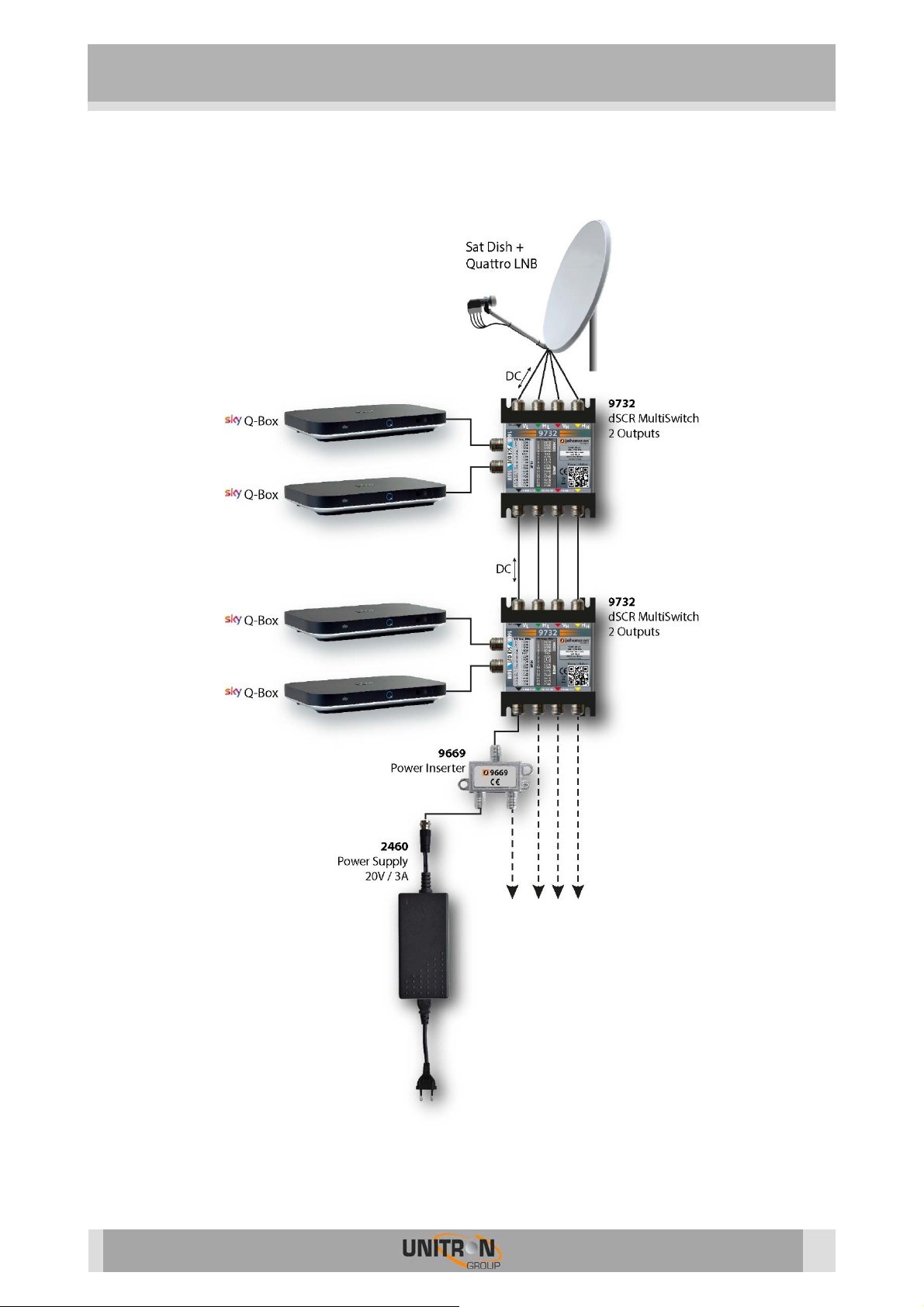
1. INSTALLATION OF THE HARDWARE
3
Page 4

dCSS/dSCR Multiswitch (Ref. 9732) v1.0
2. CONFIGURATION OF THE MODULE
Installation Mode
The device starts up in installation mode to check the equipment functionality and the correct
installation. In this mode the automatic gain control is frozen (commands for activating the
AGC are required). The multiswitch switches to SCR/CSS mode upon receiving a DiSEqC
message.
To activate one or more of the UBs a proper DiSEqC message should be received.
The installation mode starts up with the following 2 transponders active (both output signals
are having a fixed gain):
Transponder 58 (Frequency: 11880 Vertical) placed in output IF 1281.
Transponder 101 (Frequency: 12731 Horizontal) placed in output IF 2131.
CSS Mode
ONLY EN50494/SCR standard
For Installation with Legacy STB and PVR/MySKYHD SCR compatible:
Max 4 User Bands (UB1 to UB4) available (as in the LNB SCR)
Signalling DiSEqC 1.0
ONLY EN50607/dCSS standard
For NEW Installation of HMG:
12 User Bands for HMG in the range from UB5 to UB16
Signalling DiSEqC 1.0 or 2.0
CONCURRENT EN50494/EN50607 standards
For existing MULTIVISION installations (Legacy STB/PVR SCR compatible), with main STB
upgraded to Next Gen PVR/HMG:
Max 4 User Bands (UB1 to UB4) available for current STB/PVR
12 User Bands for HMG in the range from UB5 to UB16
Signalling DiSEqC 1.0 + signalling DiSEqC 2.0 in the same cable from LNB to apartment
SKY UK standard
For Installations with SKY Q-Box :
16 User bands in SCR mode
Signalling DiSEqC 1.0 or 2.0
4
Page 5

dCSS/dSCR Multiswitch (Ref. 9732) v1.0
3. TECHNICAL SPECIFICATIONS
9732
Trunk inputs - 4
Trunk outputs - 4
Frequency (MHz) - 950 – 2150
Trunk loss - 3 dB
dCSS/dSCR outputs - 2
dCSS/dSCR output connector - 75 Ohm F type (Female)
dCSS/dSCR UBs - 16+16
dCSS/dSCR output level - 85 dBµV
Return loss - >=8 dB (Typ 12 dB)
Tap loss - Not applicable, AGC (automatic Gain control)
Band and polarity selection -
Max DC current consumption - < 320mA @ 13 Volt
Power supply - From STB, power inserter or trunk (VL)
Power inserter (2460+9669 available
separately)
- 3A, 20V
DiSEqC 1.0 (unidirectional)
DiSEqC 2.0 (bidirectional)
Standard EN 50494 (SCD)
Standard EN 50607 (SCD 2)
SKY UK standard
5
Page 6

dCSS/dSCR Multiswitch (Ref. 9732) v1.0
UB
UB center
UB default BW
Usage
index
frequency (MHz)
(MHz)
1 1210 46 EN50494
2 1420 46 EN50494
3 1680 46 EN50494
4 2040 46 EN50494
5 985 46 EN50607
6 1050 46 EN50607
7 1115 46 EN50607
8 1275 46 EN50607
9 1340 46 EN50607
10 1485 46 EN50607
11 1550 46 EN50607
12 1615 46 EN50607
13 1745 46 EN50607
14 1810 46 EN50607
15 1875 46 EN50607
16 1940 46 EN50607
Legacy STB and PVR
SCR compatible
HMG 12 tuners
UB
UB center
UB default BW
index
frequency (MHz)
(MHz)
3 1680 46 SKY UK
9 1280 46 SKY UK
11 1380 46 SKY UK
14 1480 46 SKY UK
15 980 46 SKY UK
16 1030 46 SKY UK
17 1080 46 SKY UK
18 1130 46 SKY UK
19 1530 46 SKY UK
20 1580 46 SKY UK
21 1630 46 SKY UK
22 1730 46 SKY UK
23 1780 46 SKY UK
24 1830 46 SKY UK
25 1880 46 SKY UK
26 1930 46 SKY UK
6
Page 7

dCSS/dSCR Multiswitch (Ref. 9732) v1.0
4. SAFETY INSTRUCTIONS
Read these instructions carefully before connecting the unit
T o prevent fire, short circuit or shock
Do not expose the unit to rain or moisture.
Install the unit in a dry location without infiltration or condensation of water.
Do not expose it to dripping or splashing.
Do not place objects filled with liquids, such as vases, on the apparatus.
If any liquid should accidentally fall into the cabinet, disconnect the power plug.
hazard:
T o avoid any risk of
Install the unit in a well aery location and keep a minimum distance of 15 cm around the
apparatus for sufficient ventilation
Do not place any items such as newspapers, table-cloths, curtains,
on the unit that might cover the ventilation holes.
Do not place any naked flame sources, such as lighted candles, on the apparatus
Do not install the product in a dusty place
Use the apparatus only in moderate climates (not in tropical climates)
Respect the minimum and maximum temperature specifications
T o avoid any risk of electrical
Connect apparatus only to socket with protective earth connection.
The mains plug shall remain readily operable
Pull out power plug to make the different connections of cables
To avoid electrical shock, do not open the housing of adapter.
Maintenance
Only use a dry soft cloth to clean the
Do not use solvent
For repairing and servicing refer to qualified
overheating
:
shocks
:
cabinet.
personnel.
Dispose according your local authority’s recycling processes
7
Page 8

dCSS/dSCR Multiswitch (Ref. 9732) v1.0
5. CONDITIONS OF WARRANTY
Unitron N.V. warrants the product as being free from defects in material and
workmanship for a period of 24 months starting from the date of production indicated on
it. See note below.
If during this period of warranty the product proves defective, under normal use, due to
defective materials or workmanship, Unitron N.V, at its sole option, will repair or replace the
product. Return the product to your local dealer for reparation
THE WARRANTY IS APPLIED ONLY FOR DEFECTS IN MATERIAL AND WO RKMANSHIP
AND DOES NOT COVER DAMAGE RESULTING FROM:
Misuse or use of the product out of its specifications.
Installation or use in a manner inconsisten t with the technical or safety standards in
force in the country where the product is used
Use of non-suitable accessories (power supply, adapters...).
Installation in a defect system.
External cause beyond the control of Unitron N.V. such as drop, accidents,
lightning, water, fire, improper ventilation…
THE WARRANTY IS NOT APPLIED IF
Production date or serial number on the product is illegible, altered, deleted or
removed.
The product has been opened or repaired by a non-authorized person.
NOTE
Date of production is YYWW format, example 1447 = year 2014 – week 47.
For the serial number barcodes, the date corresponds to the 4 first numbers
UNITRON NV
Frankrijklaan 27
B-8970 Poperinge
Belgium
T +32 57 33 33 63
8
F +32 57 33 45 24
sales@johansson.be
www.johansson.be
 Loading...