

Page 1

Uni-trend Technology (China) Ltd.
Document No. SYSC-0-100108
January 2010
Digital Storage Oscilloscope
Communication&Control Software
User Manual and Installation Instructions
Communication & Control Software for UTD2000M Oscilloscopes User Manual
Page of 24
1
Page 2

Uni-trend Technology (China) Ltd.
Copyright Information
1. Uni-Trend Technology (China) Limited. All rights reserved.
2. Products of the Company are protected by patents granted and pending in the
People’s Republic of China.
3. Information contained in this manual supercedes all information in previously
published versions.
4. The Company reserves the right to change specifications and prices.
Note : Uni-T is the registered trademark of Uni-Trend Technology (China)
Limited.
Communication & Control Software for UTD2000M Oscilloscopes User Manual
Page of 24
2
Page 3

Uni-trend Technology (China) Ltd.
Table of Contents
Chapter 1 Installing the communication and control software for your
digital storage oscilloscope......................................................................4
1.1 Hardware requirements ..............................................................................................................4
1.2. Installing the software ...............................................................................................................8
1.3 Installing the driver ....................................................................................................................8
1.4 Software startup ........................................................................................................................13
Chapter 2 Getting to know your digital storage oscilloscope
communication and control software...................................................15
2.1 The control panel ......................................................................................................................15
2.2. Main menu ...............................................................................................................................16
Chapter 3 Operation guide for the digital storage oscilloscope
communication and control software...................................................18
3.1 USB interface controls .............................................................................................................18
Chapter 4 System Prompts and Trouble-shooting..............................21
4.1 System prompts..........................................................................................................................21
4.2 Trouble-shooting ......................................................................................................................21
Communication & Control Software for UTD2000M Oscilloscopes User Manual
Page of 24
3
Page 4
Uni-trend Technology (China) Ltd.
Chapter 1 Installing the communication and control software
for your digital storage oscilloscope
1. Hardware requirements
Equipment requirements Minimal
Oscilloscope UTD2000M Series Digital Storage Oscilloscope
Computer Windows 2000/XP/Vista, 128 MB RAM, 16X
CD-ROM or better (Vista users please refer to its
individual hardware requirements), VGA display or
better, high speed USB2.0 interface.
Connection cable Two-terminal USB/HOST connection cable
2. Installing the software
Your UTD2000M Series Digital Storage Oscilloscope (“Oscilloscope”) comes with an
oscilloscope communication and control software (contained in the CD-Rom supplied
with your oscilloscope).
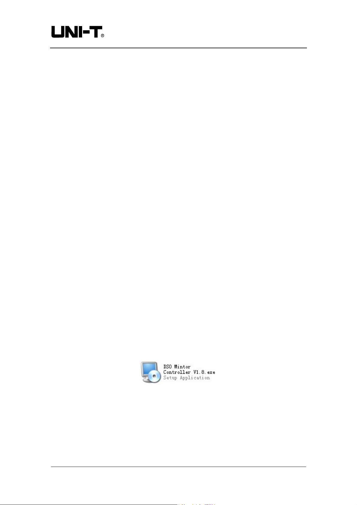
File name:
Installation :
Step one : Insert the CD-Rom supplied with your oscilloscope in the CD-Rom drive of
Note : 1. The installation pack downloaded online must be unzipped before
Step two : Double left click the mouse to run the oscilloscope communication and
Monitor & Controller Software for UTD2000M V1.8
the computer. Wait for the system to read and find the oscilloscope
communication and control software contents (Figure 1-1)
Figure 1-1
application.
2. The software supports Windows 2000, Windows XP and Vista operating
systems. On Vista only USB2.0 communication protocol is supported.
control software installation as shown in Figure 1-1. A welcome screen
Communication & Control Software for UTD2000M Oscilloscopes User Manual
Page of 24
4
Page 5
Uni-trend Technology (China) Ltd.
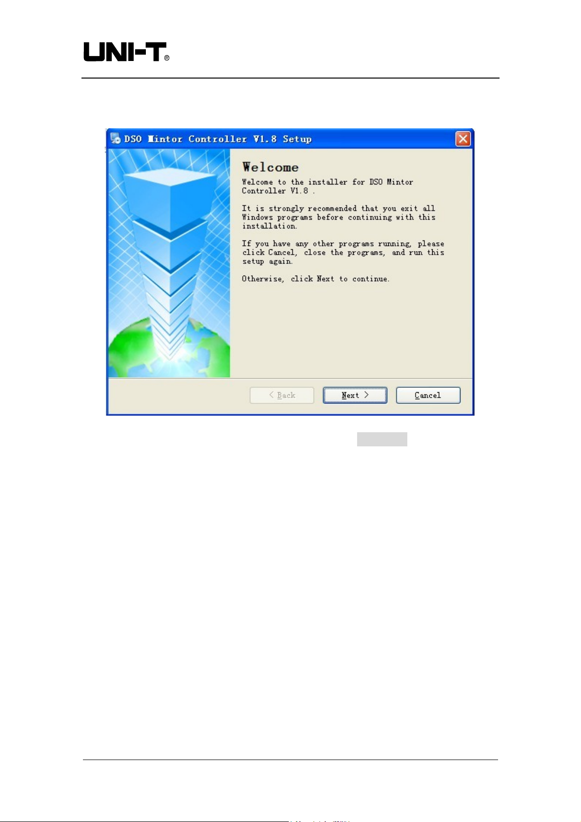
will pop up automatically to guide you through software installation, as
shown in Figure 1-2 :
Figure 1-2
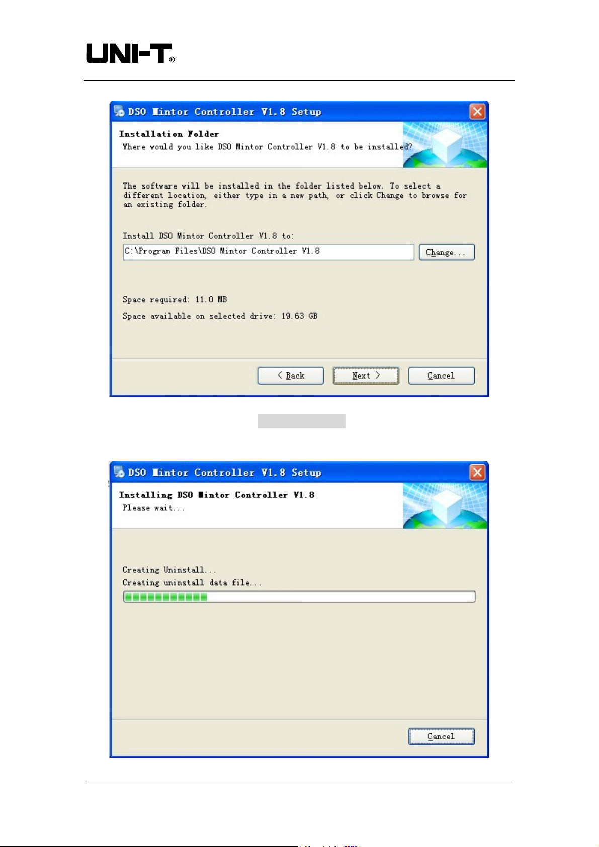
Step three : Read the prompt in Figure 1-2 then click the NEXT (N) button to enter the
next step, as shown in Figure 1-3
Communication & Control Software for UTD2000M Oscilloscopes User Manual
Page of 24
5
Page 6
Uni-trend Technology (China) Ltd.
Figure 1-3
Step four : In Figure 1-3, click the CHANGE (H)….. button to specify the installation
path of the software, then click NEXT. You can also click NEXT directly
to use the default path. Enter the screen shown in Figure 1-4.
Communication & Control Software for UTD2000M Oscilloscopes User Manual
Page of 24
6
Page 7
Uni-trend Technology (China) Ltd.
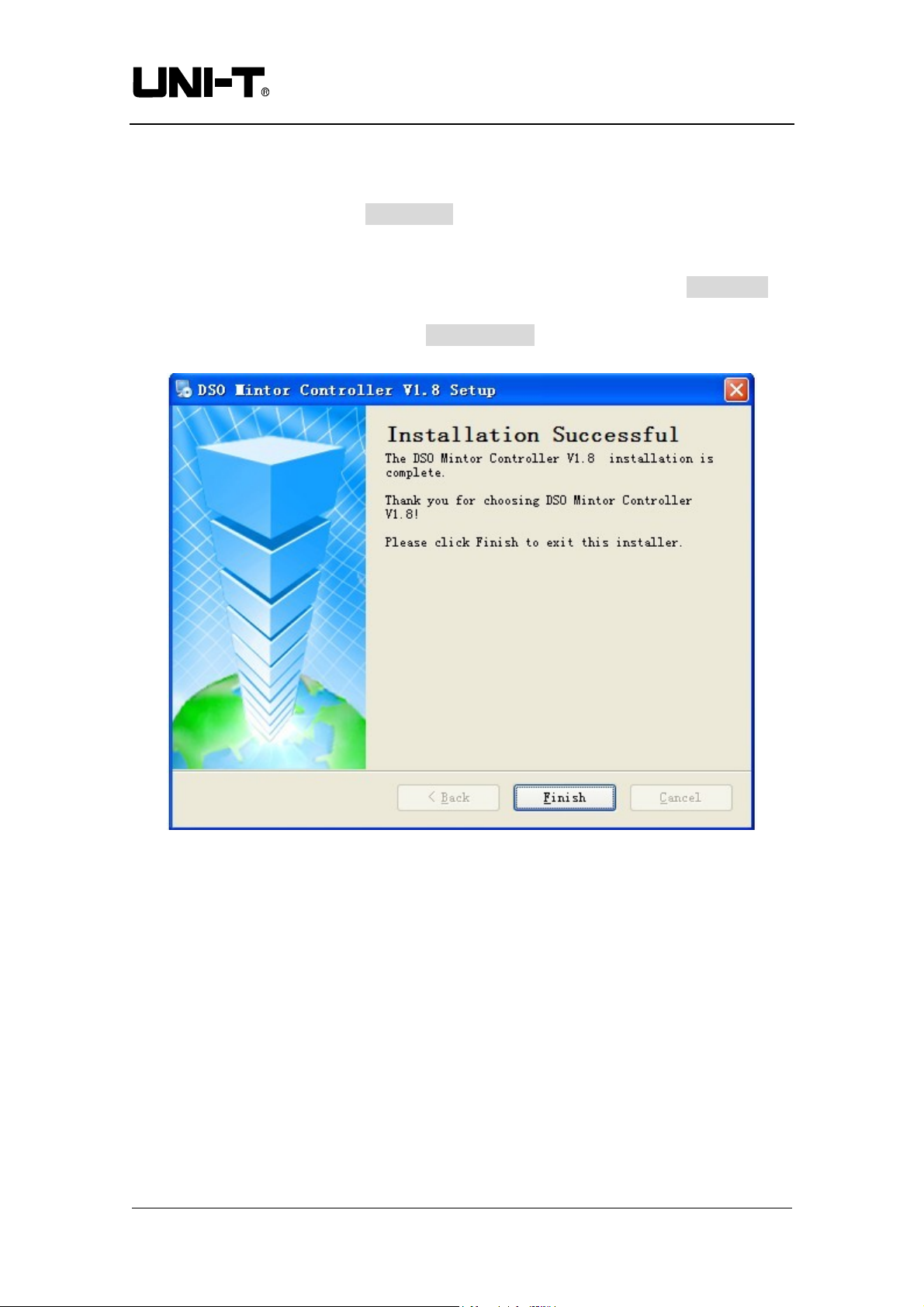
Figure 1-4
Step five :When automatic installation is complete and the box shown in Figure 1-5
pops up, click the FINISH (F) button. Your oscilloscope communication
and control software is now successfully installed on your computer and
ready for use.
To return to the screen of the previous installation step, click BACK (B) on
any installation guide page.
To stop installation, press CANCEL (C) on any installation guide page.
Figure 1-5
3. Installing the driver
After installing the oscilloscope communication and control software, if you intend to
use the USB port of the oscilloscope for software communication and control, you must
install the USB driver. You can do this either by manual pre-installation or automatic
installation :
Page of 24
Communication & Control Software for UTD2000M Oscilloscopes User Manual
7
Page 8
Uni-trend Technology (China) Ltd.
(1) Manual pre-installation of the USB driver
Installation steps are as follows :
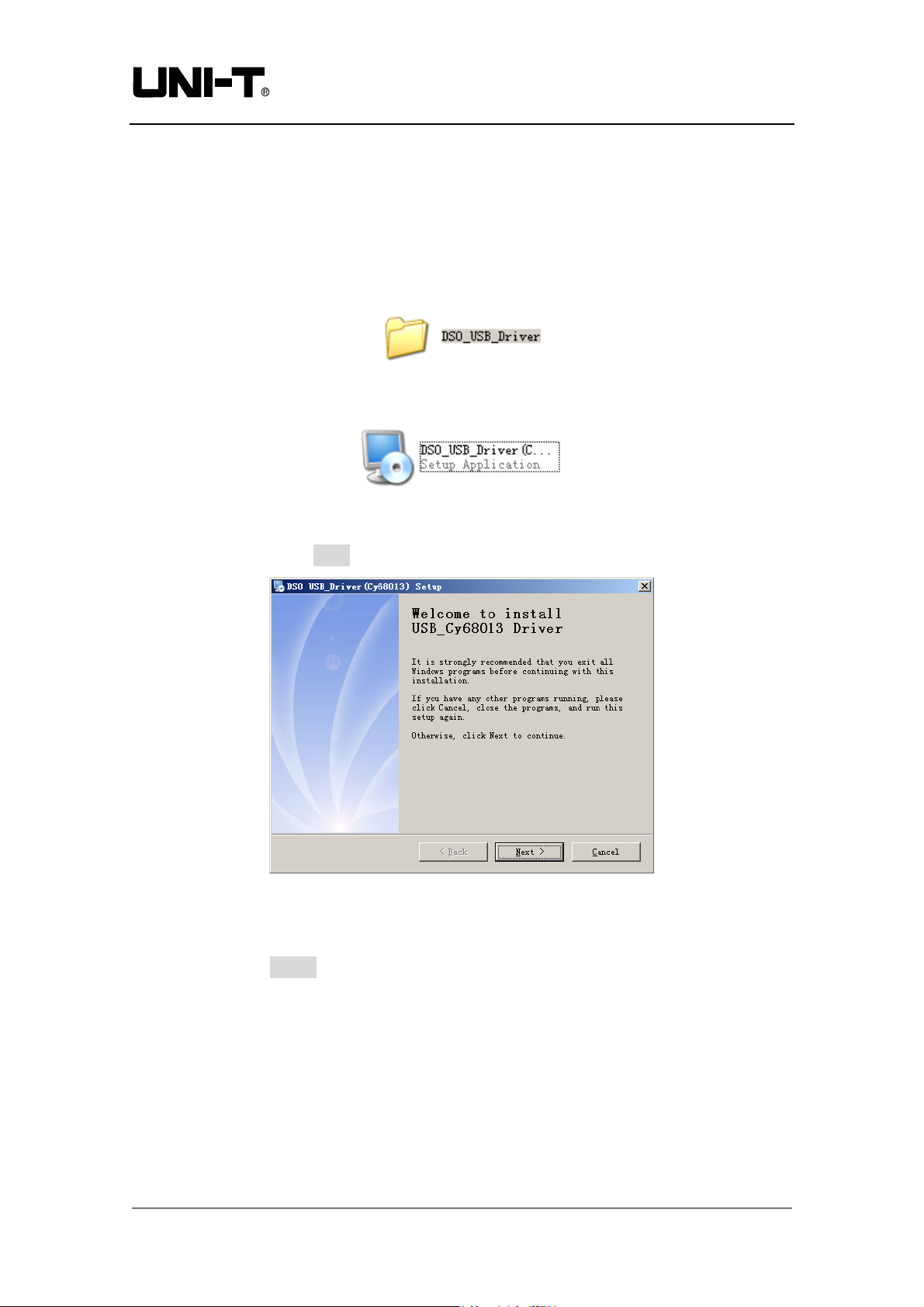
Step 1 : Insert the CD-Rom supplied with your oscilloscope in the CD-Rom disk drive
of the computer. Wait for the system to read the CD-Rom and find the
DSO_USB interface driver (Figure 1-8).
Figure 1-8
Install DSO_USB_Driver (Cy68013) (Figure 1-9).
Figure 1-9
Double left click the mouse to run DSO_USB_Driver. An installation box will pop up
(Figure 1-10). Click the Next button to enter the automatic installation page.
Figure 1-10
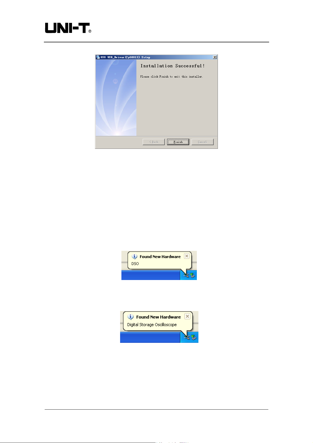
Step 3 : When automatic installation is complete, as indicated by the pop-up box in
Figure 1-11, click Finish in Figure 1-11. Your USB driver is now successfully installed
on your computer and ready for use.
Page of 24
Communication & Control Software for UTD2000M Oscilloscopes User Manual
8
Page 9
Uni-trend Technology (China) Ltd.
Figure 1-11
(2) Automatic Installation
1. There is a USB device port on the rear panel of your UTD2000E_3000E Series
Digital Storage Oscilloscope. With the supplied USB A-B cable, you can connect the
USB device port to the USB Host port of the computer and obtain power supply for the
oscilloscope.
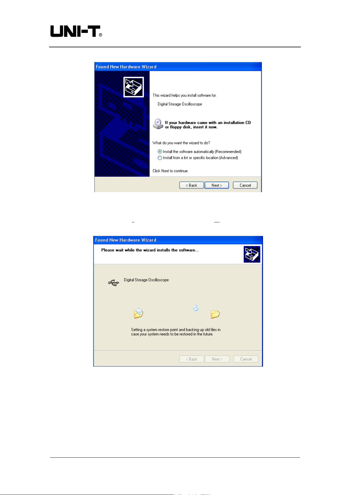
2. After checking that connection and power supply are normal, power on the digital
storage oscilloscope. When the operation status screen appear s, a prompt will appear at
the right bottom corner to indicate “New hardware DSO detected”, as shown in Fig
1-12.
Figure 1-12
Next, an icon will be created for the “New hardware DSO detected”, as shown in
Fig 1-13.
Figure 1-13
Then a “hardware update wizard” dialog box will pop up on the desktop, as shown
in Fig 1-14.
Page of 24
Communication & Control Software for UTD2000M Oscilloscopes User Manual
9
Page 10
Uni-trend Technology (China) Ltd.
Fig 1-14
3. In the new hardware wizard dialog box in Fig 1-12, select the “automatic software
installation (recommended) (I) option, then click [NEXT (N)] to enter the automatic
driver search and installation page, as shown in Fig 1-15.
Figure 1-15
4. As shown in Fig 1-15, the hardware installation wizard of your digital storage
oscilloscope begins automatic searching and installing the USB driver for the
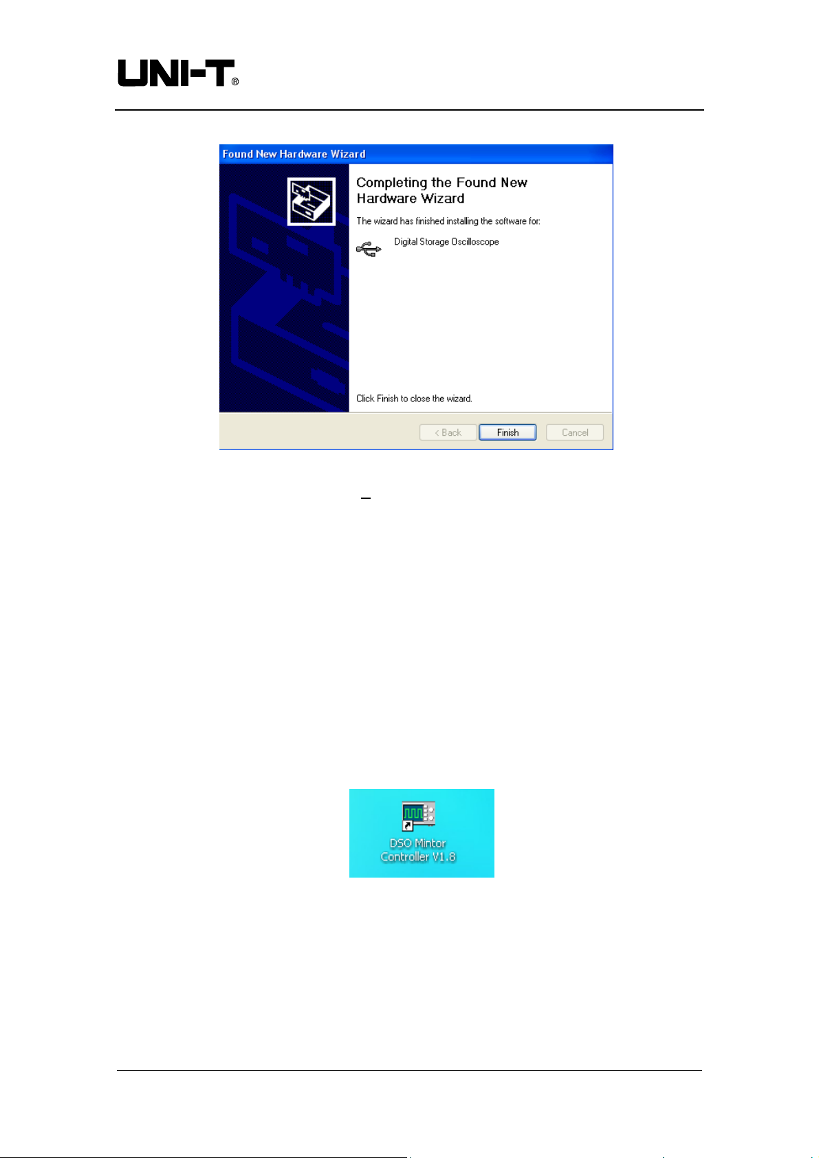
oscilloscope communication and control software. When installation is complete the
dialog box shown in Fig 1-16 pops up.
Page of 24
Communication & Control Software for UTD2000M Oscilloscopes User Manual
10
Page 11
Uni-trend Technology (China) Ltd.
Figure 1-16
5. In Fig 1-16, click the [FINISH (F)] button. Your USB driver is now installed, and
instant communication and control are enabled between the oscilloscope and the
software. Please read “3.1 USB Interface Controls” in “Chapter 3 : Operation guide
for the oscilloscope communication and control software” of this booklet prior to
operation.
4. Software startup
After successful installing the digital storage oscilloscope communication and control
software, you can start the software on the computer in two ways.
(1) After successful installation of the software, a shortcut icon will be automatically
created on your computer desktop, as shown in Fig. 1-17. Double left click this
icon to start the digital storage oscilloscope communication and control software.
Figure 1-17
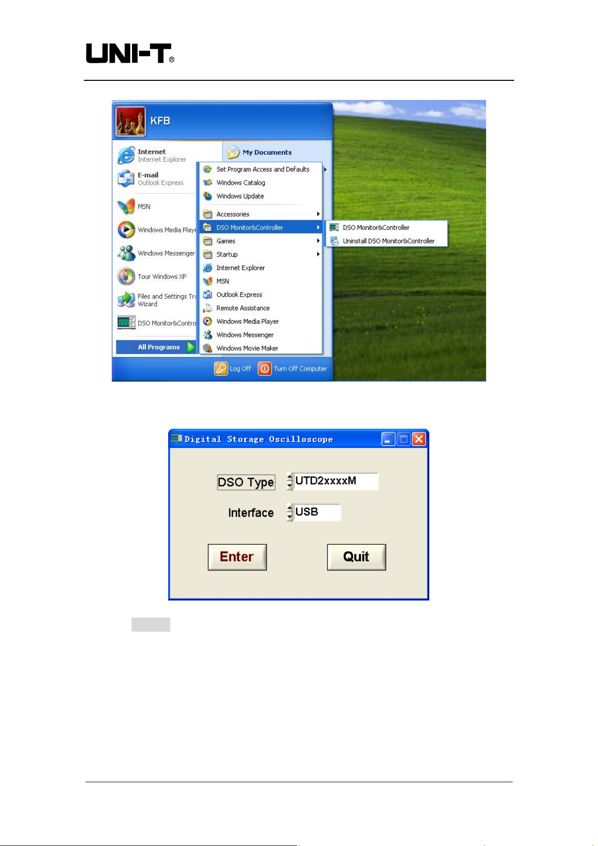
(2) Alternatively, you can start the software as follows : START→Programmes→DSO
real-time monitor→DSO real-time monitor, as shown in Figure 1-18.
Communication & Control Software for UTD2000M Oscilloscopes User Manual
Page of 24
11
Page 12
Uni-trend Technology (China) Ltd.
Figure 1-18
(3) In the pop-up dialogue box, select the interface type that matches your
oscilloscope model (Figure 1-19).
Figure 1-19
(4) Click ENTER to enter the software control screen.
Communication & Control Software for UTD2000M Oscilloscopes User Manual
Page of 24
12
Page 13
Uni-trend Technology (China) Ltd.
Chapter 2 Getting to know your digital storage oscilloscope
communication and control software
1. The control panel
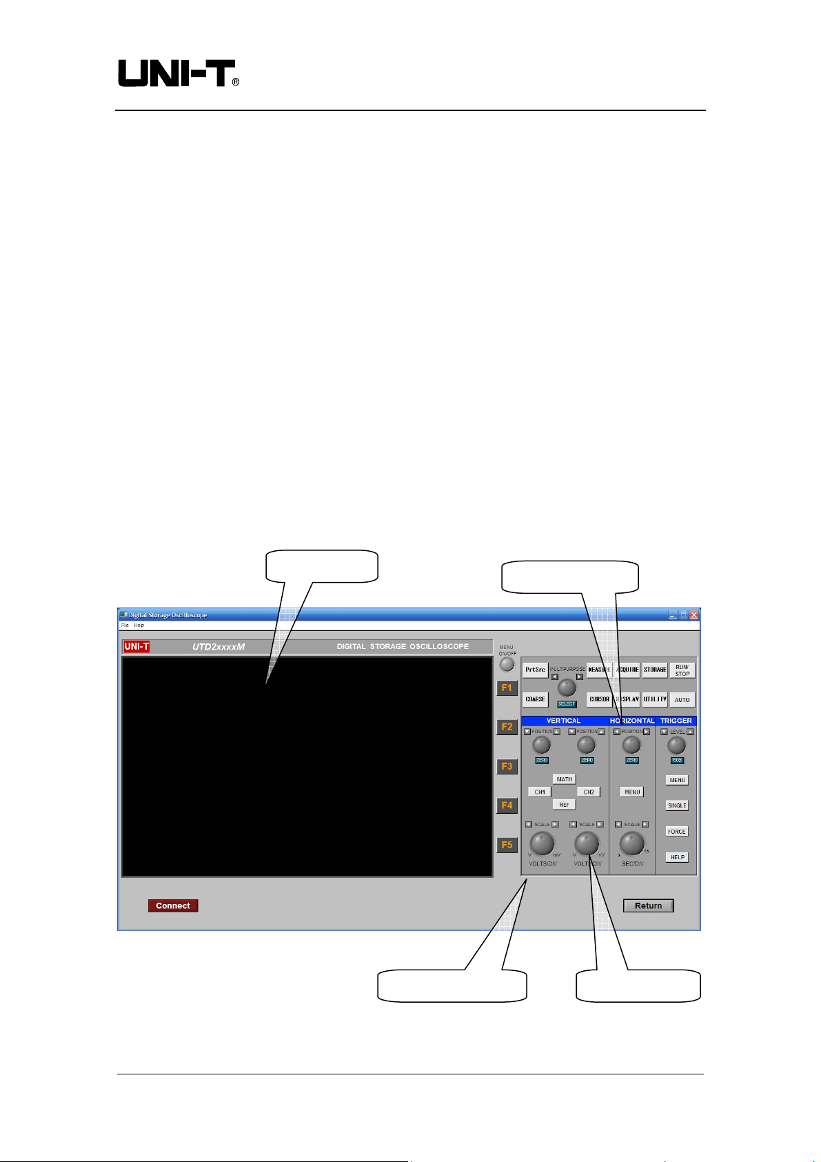
When the oscilloscope communication and control software is activated, a display
panel similar to the digital storage oscilloscope operation interface will pop up. This is
the virtual oscilloscope control panel. When transmitting data, you can observe the
current waveform displayed by the oscilloscope on the virtual control panel. This
interface also features menus, controls and knobs for accessing waveform and channel
parameters (please disable the “data transmission” function before using the menus to
access information). Please see below for detailed operation instructions :
Virtual display
Transfer indicator
Communication & Control Software for UTD2000M Oscilloscopes User Manual
Virtual control panel Range indicator
Figure 2-1
Page of 24
13
Page 14

Uni-trend Technology (China) Ltd.
2. Main menu
Figure 2-1 shows two menus under the main menu on the top left corner : document
and help. At the bottom of the screen you will find four menus : record path setup,
record, playback path setup and playback. Their operation instructions are as follows :
1. Document
Transmitting and saving data : This means saving the waveform on the virtual
display to the computer or other storage media. Select DOCUMENT→DATA
TRANSMISSION & SAVE, then save the document in *.sav format on the
computer hard disk or a mobile hard disk. You can name the document in anyway
you like.
Return : Return to the model selection menu.
2. Help
Major functions of the digital storage oscilloscope communication and control
software are displayed.
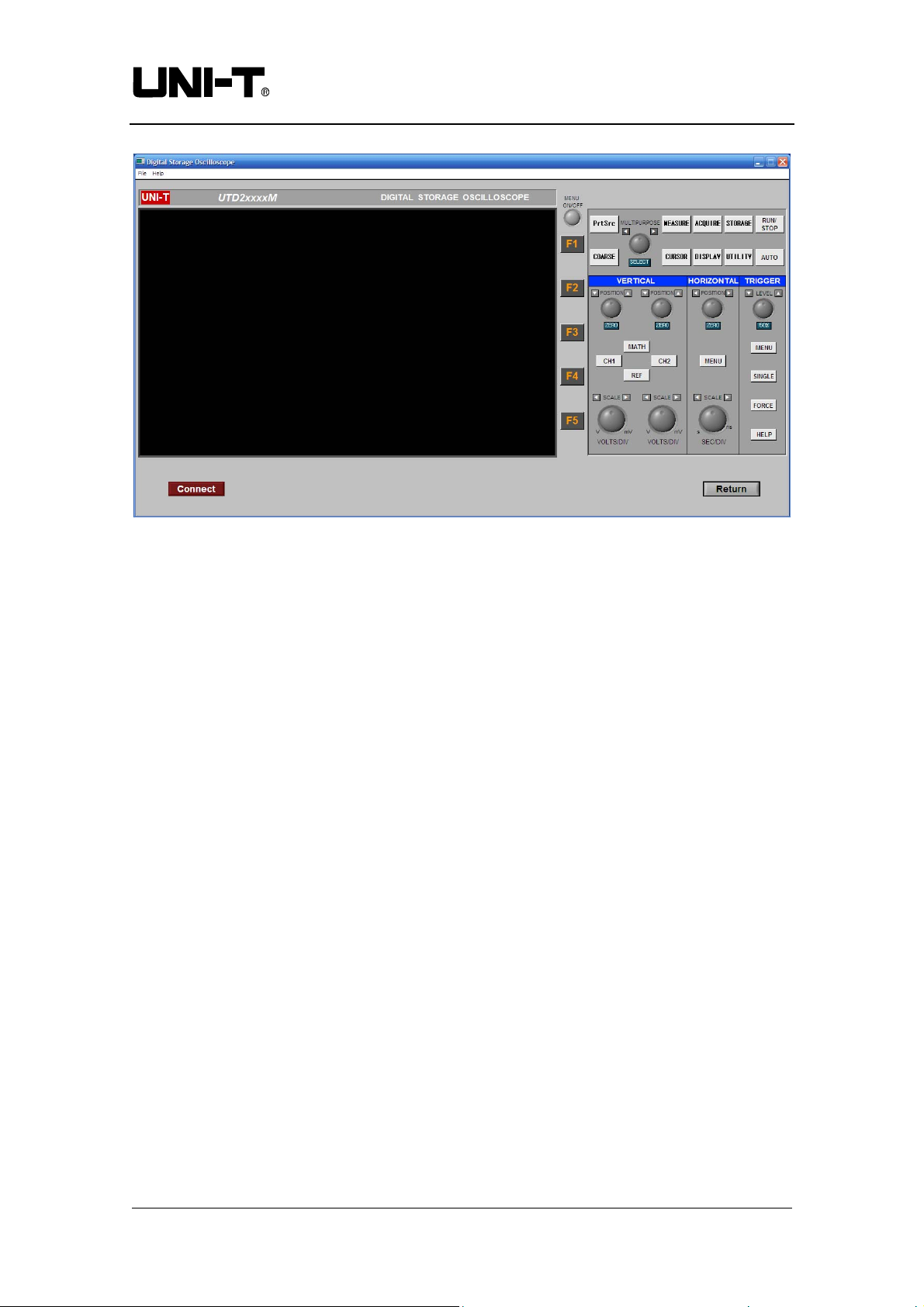
◆ Remote monitoring and control : You can control your digital storage
oscilloscope remotely with the communication and control software. In the remote
control mode, the computer will show a virtual display and control panel similar to
the control panel of the digital storage oscilloscope. The virtual control panel is
shown in Figure 2-2.
Communication & Control Software for UTD2000M Oscilloscopes User Manual
Page of 24
14
Page 15
Uni-trend Technology (China) Ltd.
Virtual control panel
Figure 2-2
The sign of every button or knob on the virtual control panel is identical to that on the
oscilloscope control panel. You can click the same buttons to operate the corresponding
functions. To use the virtual control panel efficiently, you must be familiar with all
function menus as well as the current status of the oscilloscope. Waveforms on the
virtual display panel are updated in real time and maintain synchronized with the
waveforms on the oscilloscope.
Communication & Control Software for UTD2000M Oscilloscopes User Manual
Page of 24
15
Page 16
Uni-trend Technology (China) Ltd.
Chapter 3 Operation guide for the digital storage oscilloscope
communication and control software
By now you should have grasped the basic structure, menu options and functions of the
oscilloscope communication and control software. In the following pages you will find
ore detailed instructions on how to operate the software. In this chapter, we will give
guidance on the USB control mode.
USB interface controls
To enjoy optimal software performance, we recommend you to read the oscilloscope
user manual and this chapter to familiar with application.
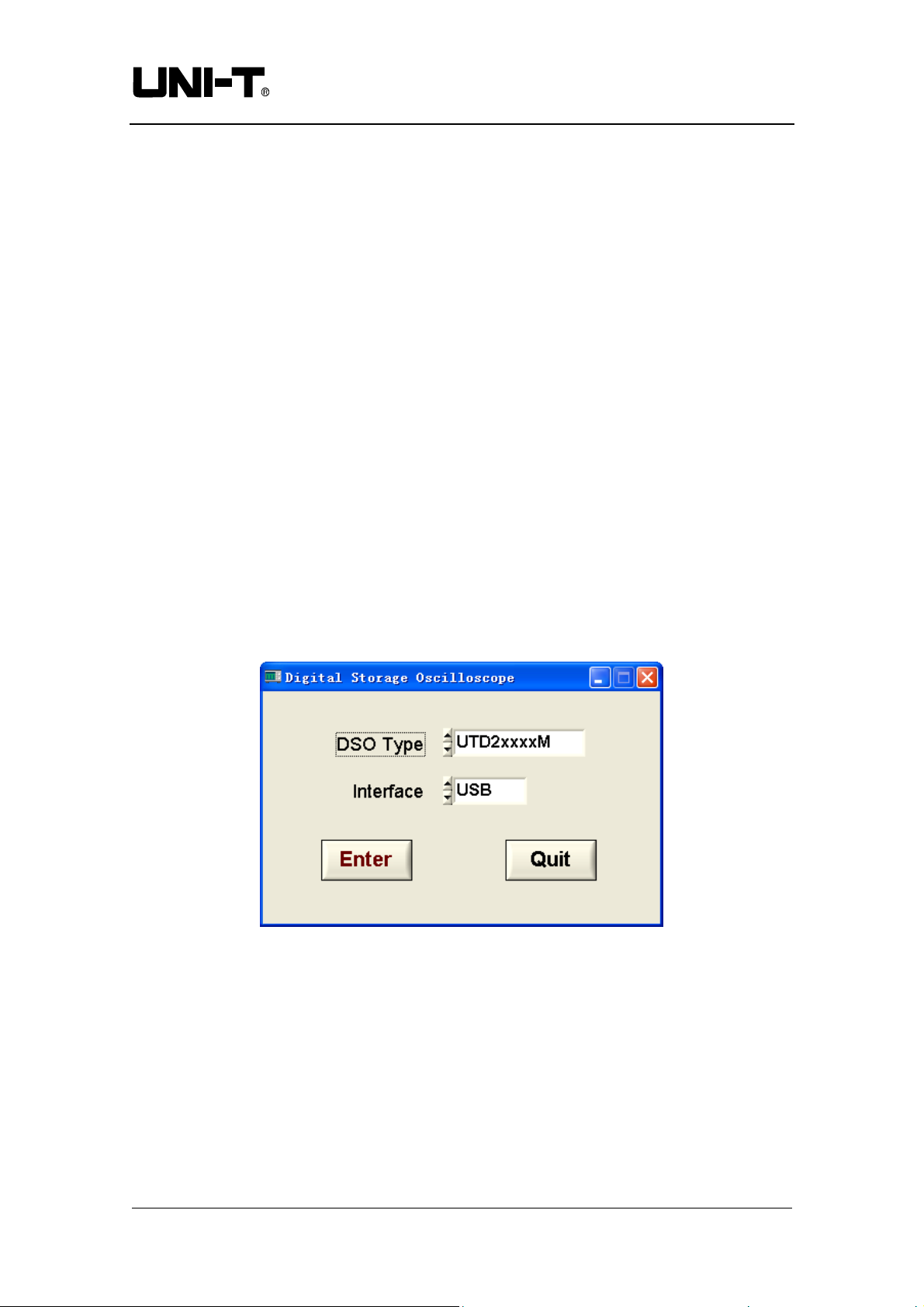
After installing the software and driver properly, connect the two ends of the
USB/HOST cable. Power on the oscilloscope and activate the software. The software
control panel shown in Figure 3-1 will appear on your computer screen, where you can
select software model and interface type.
Figure 3-1
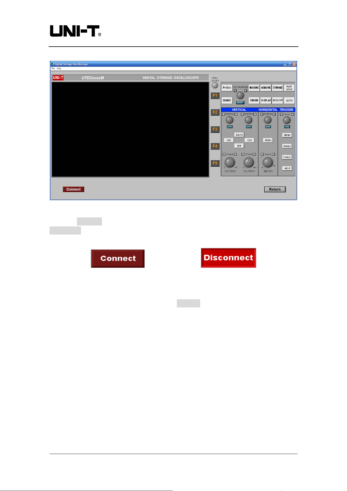
Select the model and interface type that match your oscilloscope. Click to enter. A
communication and control software control screen shown in Figure 3-2 pops up.
Page of 24
Communication & Control Software for UTD2000M Oscilloscopes User Manual
16
Page 17
Uni-trend Technology (China) Ltd.
Figure 3-2
Click the Connect button to turn the equipment “ON”. The button now changes into
Disconnect.When set to Disconnect, it is “OFF”, as shown in Figure 3-3.
Figure 3-3 Connect Equipment and Disconnect Equipment
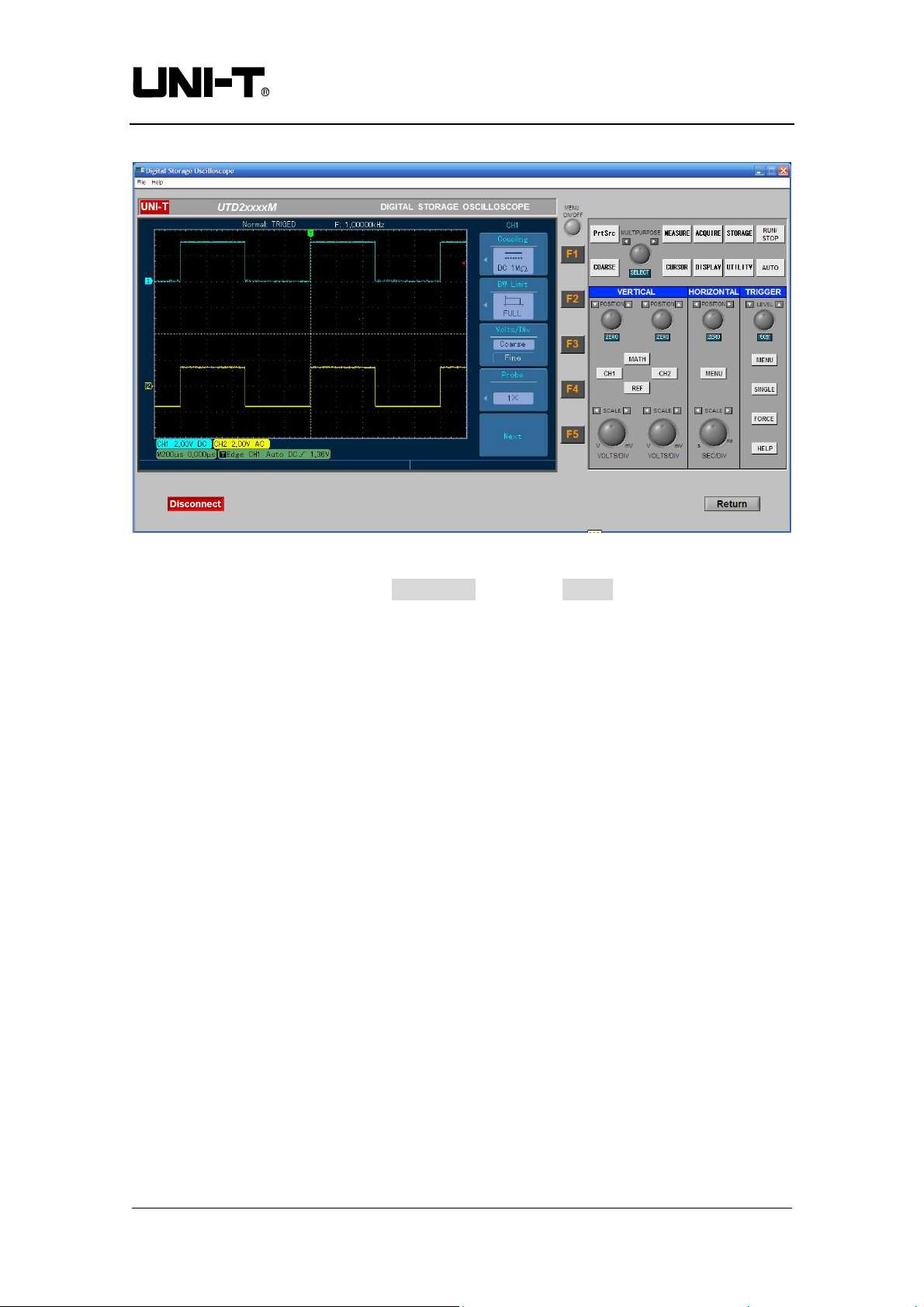
To enable the remote control mode, click the Connect button to change it to “ON”. Use
the buttons on the virtual control panel (Figure 3-4) as instructed by the oscilloscope
user manual to control your digital storage oscilloscope.
Communication & Control Software for UTD2000M Oscilloscopes User Manual
Page of 24
17
Page 18
Uni-trend Technology (China) Ltd.
Figure 3-4
When operation is complete, click Disconnect, then click Return to close the remote
control window and quit remote control.
Communication & Control Software for UTD2000M Oscilloscopes User Manual
Page of 24
18
Page 19
Uni-trend Technology (China) Ltd.
Chapter 4 System Prompts and Trouble-shooting
1. System prompts
Equipment connection or model error : Check the selected oscilloscope model and
communication interface type. Also see if the equipment is correctly connected, or if
the software driver is the update version.
2. Trouble-shooting
(1) If connection fails after pressing CONNECT EQUIPMENT, take the following
steps :
① Check whether the oscilloscope power plug is properly connected.
② Check the setups of the oscilloscope and the control software.
③ Check whether the cable connection between module and PC is in order.
④ Ensure the USB driver is properly installed.
⑤ After carrying out the above checks, restart the software and oscilloscope to
continue operation.
(2) If you are unable to update the software driver, take the following steps :
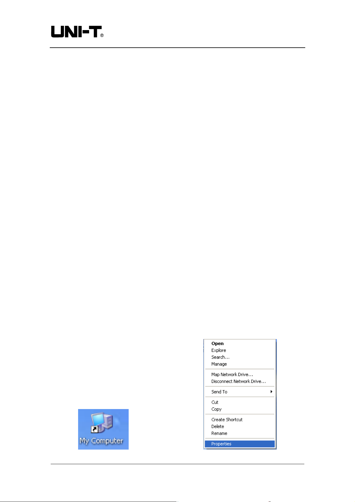
① Right click on your computer desktop as shown in Figure 4-1 to activate the
right-click menu in Figure 4-2.
Communication & Control Software for UTD2000M Oscilloscopes User Manual
Page of 24
19
Page 20
Uni-trend Technology (China) Ltd.
Figure 4-1 Figure 4-2
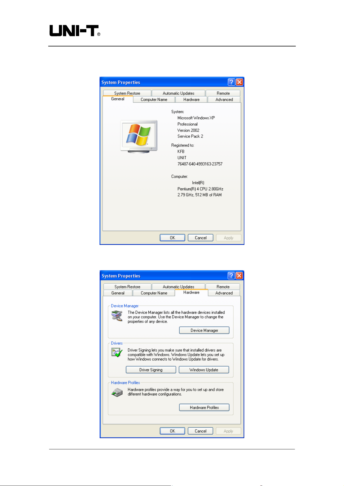
② In Figure 4-2, select ATTRIBUTE and right click to pop up Figure 4-3.
Figure 4-3
③ Select HARDWARE in Figure 4-3. Figure 4-4 is displayed.
Communication & Control Software for UTD2000M Oscilloscopes User Manual
Page of 24
20
Page 21
Uni-trend Technology (China) Ltd.
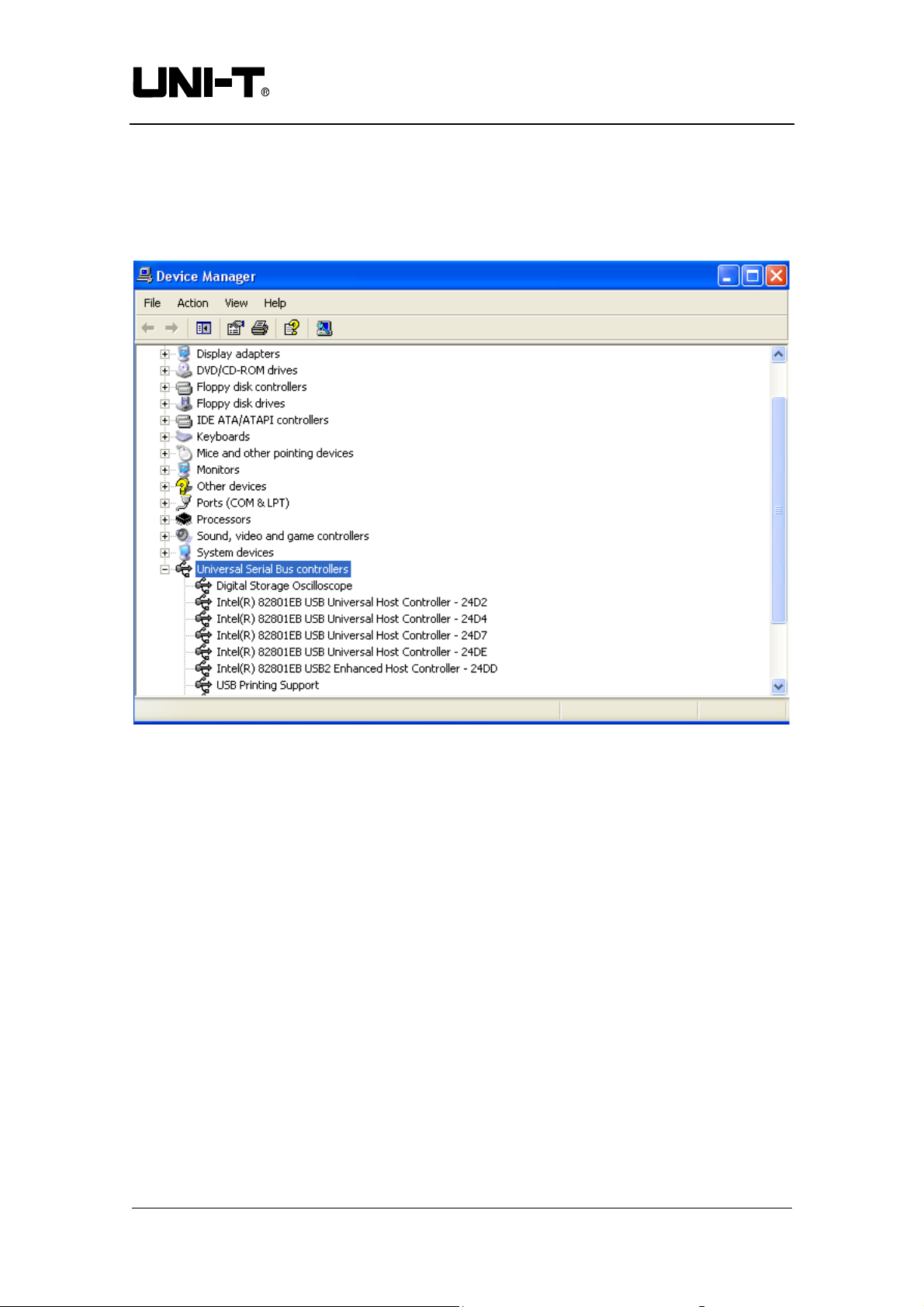
Figure 4-4
④ Select EQUIPMENT MANAGER (D) in Figure 4-4. Figure 4-5 pops up.
Figure 4-5
⑤ In EXTERIOR INTERFACE in Figure 4-5, delete OSCILLOSCOPE to restart
the oscilloscope. Select automatic driver update to upgrade the software.
Note : When the communication and control software is communicating with the
digital storage oscilloscope, do not unplug the connection cable to disconnect
communication. This may cause abnormalities.
Communication & Control Software for UTD2000M Oscilloscopes User Manual
Page of 24
21
Page 22

Uni-trend Technology (China) Ltd.
Copyright Statement
Copyright of this User Manual is owned by Uni-Trend Technology (Chengdu) Limited.
Unless with prior written authorization from the company, no individual or firm may
publish or change any contents herein contained in any way whatsoever.
Thank you!
Communication & Control Software for UTD2000M Oscilloscopes User Manual
Page of 24
22
 Loading...