

UNI-TREND UT 161D Instructions

P/N:110401109612X
UT161 Series
1000V True RMS Digital Multimeter
User Manual

Preface
Thank you for purchasing this brand new product. In order to use this product
safely and correctly, please read this manual thoroughly, especially the safety
notes.
After reading this manual, it is recommended to keep the manual at an easily
accessible place, preferably close to the device, for future reference.
Limited Warranty and Liability
Uni-Trend guarantees that the product is free from any defect in material and
workmanship within one year from the purchase date. This warranty does not
apply to damage ca used b y acci dent, negli gence , misu se, mo dific ation ,
contamination or mishandling. The dealer shall not be entitled to give any other
warranty on behalf of Uni-Trend. If you need warranty service within the warranty
period, please contact your seller directly.
Uni-Trend will not be responsible for any special, indirect, incidental or subsequent
damage or loss caused by using this device.

Table of Contents
I. Overview -------------------------------------------------------------4
II. Accessories ----------------------------------------------------------4
III. Safety Instructions -------------------------------------------------5
IV. Electrical Symbols -------------------------------------------------6
V. External Structure -------------------------------------------------7
VI. LCD Display -------------------------------------------------------8
VII. Function Dial and Function Buttons --------------------------9
VIII. Operating Instructions -----------------------------------------11
IX. Specifications -----------------------------------------------------25
X. Maintenance --------------------------------------------------------35
I. Overview
The UT161B/UT161D/UT161E is a handheld true RMS digital multimeter with
high reliability and security (UT161B/UT161D: 6000 counts; UT161E: 22000
counts). With large screen, high resolution analog pointer display, full scale
overload protection, and unique appearance design, it becomes a new practical
electrical measuring meter. The meter can measure AC/DC voltage/current,
resistance, diode, transistor hFE (UT161E), continuity, capacitance, frequency,
duty ratio, temperature (UT161D), etc. Featuring data transmission, data hold,
relative value measurement, peak measurement (UT161D/UT161E), internal
temperature alarm, low battery indication, backlight, auto power off, and NCV
functions, the meter is an ideal measuring tool for many application fields.
II. Accessories
Open the package box and take out the meter. Please double check whether
the following items are missing or damaged.
1. User manual --------------------------------------------------- 1 pc
2. Test leads ------------------------------------------------------ 1 pair
3. Adapter socket (UT161D/UT161E) ---------------------- 1 pc
4. K-type thermocouple (UT161D) -------------------------- 1 pc
5. USB cable ----------------------------------------------------- 1 pc
6. Download operation guide --------------------------------- 1 pc
7. 1.5V AAA batteries ------------------------------------------- 4 pcs
If any of the above is missing or damaged, please contact your supplier
immediately.

III. Safety Instructions
The meter is designed and manufactured according to IEC61010-1 safety standard,
and conforms to CAT III 1000V, CAT IV 600V, and pollution degree 2. If the meter
is used in a manner not specified by the manufacturer, the protection provided
by the meter may be impaired.
1. Before use, please check if there is any item which is damaged or behaving
abnormally. If any abnormal item (such as bare test lead, damaged meter
casing, broken LCD, etc.) is found, please do not use the meter.
2. Do not use the meter if the rear cover or the battery cover is not completely
covered up, or it may pose a shock hazard!
3. Damaged test leads must be replaced with ones of the same model or same
electrical specifications.
4. During measurement, do not touch any exposed wires, connectors, unused
inputs or circuits being measured.
5. Use caution when working with voltages above AC 30Vrms, 42Vpeak or DC
60V. Keep fingers behind the finger guards of the test leads to prevent electric
shock.
6. If the range of the measured value cannot be determined, the meter must be
operated at the maximum range.
7. Do not apply more than the rated voltage or current marked on the meter
between the terminals or between any terminal and earth ground.
8. Place the function dial in the correct position before measurement.
9. Before measuring resistance, diode, continuity, or capacitance, switch off the
power supply of the circuit, and fully discharge all capacitors.
10.Before measuring current, make sure the fuses are intact.
11.Do not use or store the meter in high temperature, high humidity, flammable,
explosive, or strong magnetic field environments.
12.Do not change the internal circuit of the meter to avoid damage to the meter
or user!
13.When “ ” is displayed, please replace the batteries in time to ensure
measurement accuracy.
14.Turn off the meter in time after measurement. If the meter is not in use for a
long time, please remove the batteries.
IV. Electrical Symbols
Symbol
CAT III
CAT IV
Description
Warning or Caution
Caution, possibility of electric shock
Both direct and alternating current
Equipment protected throughout by DOUBLE INSULATION
or REINFORCED INSULATION
Earth (ground) Terminal
Complies with European Union standards
Conforms to UL STD 61010-1, 61010-030, 61010-2-033, Certified
to CSA STD C22.2 No. 61010-1, 61010-030, 61010-2-033.
It is applicable to testing and measuring circuits connected to the
distribution part of the building's low-voltage MAINS installation.
It is applicable to testing and measuring circuits connected at
the source of the building’s low-voltage MAINS installation.

V. External Structure (Picture 1)
1. NCV detector
2. Indicator light
3. LCD display
4. Function buttons
5. Function dial
6. Input terminals
7. USB (Bluetooth) access port
8. Test lead slots
9. Nut for external holder
10.Battery compartment fixing screw
11.Tilt stand
Picture 1
VI. LCD Display (Picture 2, Picture 3)
Picture 2 UT161B/UT161D Picture 3 UT161E
Symbol
AC/DC
Ω, kΩ, MΩ
mV, V
μA, mA, A
nF, μF, mF
Hz, %
NCV
P-MAX/P-MIN
MAX/MIN
°C/°F
LoZ
hFE
TRMS
Description
Measured voltage is >30V (AC or DC)
Data hold
Negative reading
AC/DC measurement
Low battery indication
Auto range
Diode test
Continuity test
Relative value measurement
Resistance units: ohm, kilohm, megaohm
Voltage units: millivolt, volt
Current units: microampere, milliampere, ampere
Capacitance units: nanofarad, microfarad, millifarad
Frequency, duty ratio
Data transmission
Transistor magnification (UT161E)
Non-contact voltage detection
Peak measurement (UT161D/UT161E)
Maximum/Minimum measurement
Celsius/Fahrenheit (UT161D)
Low impedance measurement (UT161D)
Transistor magnification measurement (UT161E)
Auto power off
True RMS
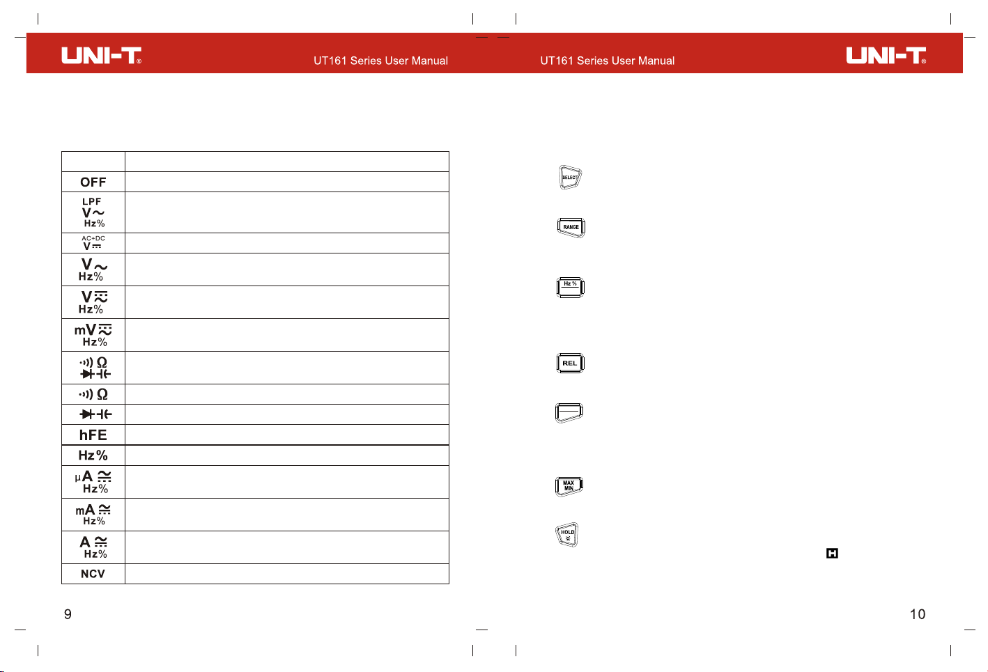
VII. Function Dial and Function Buttons
1. Function Dial
Dial Position
Power off
AC voltage measurement/Low pass filter measurement/
Frequency and duty ratio measurement (UT161E)
DC voltage measurement/AC+DC measurement (UT161E)
AC voltage measurement/Frequency and duty
ratio measurement (UT161B)
AC/DC voltage measurement/Frequency and
duty ratio measurement (UT161D)
AC/DC millivolt voltage measurement/Frequency
and duty ratio measurement
Diode test/Continuity test/Resistance measurement/
Capacitance measurement (UT161D/UT161E)
Continuity test/Resistance measurement (UT161B)
Diode test/Capacitance measurement (UT161B)
Transistor magnification measurement (UT161E)
Frequency and duty ratio measurement
AC/DC microampere current measurement/
Frequency and duty ratio measurement
AC/DC milliampere current measurement/
Frequency and duty ratio measurement
AC/DC ampere current measurement/Frequency
and duty ratio measurement
Non-contact voltage detection
Description
2. Function Buttons
Short press: Press a button for less than 2s.
Long press: Press a button for more than 2s.
1) Button
Short press to switch between functions in each compound function position.
2) Button
Short press to enter the manual range mode and change the range.
Long press to exit the manual range mode.
USB
3) Button
Short press to switch between frequency and duty ratio measurement.
Long press to turn on/off data communication (note: only available when USB
communication module is inserted into the casing).
4) Button
Short press to enter/exit the relative value measurement mode.
PEAK
MAX MIN
5) Button
Short press to cycle through the measured maximum and minimum.
Long press to cycle through the peak maximum and peak minimum
(UT161D/UT161E).
6) Button
Short press to cycle through the measured maximum and minimum (UT161B).
7) Button
Short press to hold the measurement on the display and “ ” will be displayed.
Short press again to cancel data hold.
Long press to turn on/off the backlight.
 Loading...