

Page 1

1
UNITEST
®
Instruction Manual
Cat. No. 9095
®
TELARIS 0751
Page 2

Content ............................................................................................Page
1.0 Introduction ....................................................................................4
1.1 Model and Type Designation/Identification ......................................4
1.2 Product Description ........................................................................4
1.3 Scope of Supply ..............................................................................5
1.4 Optional Accessories ......................................................................5
2.0 Transport and Storage......................................................................6
3.0 Safety Measures ..............................................................................6
3.1 Appropriate Usage ..........................................................................7
4.0 Operation Elements and Display ......................................................8
4.1 Front Panel ......................................................................................8
4.2 LC Display........................................................................................10
5.0 General Information to Perform Measurements ..............................10
5.1 Explanations of Terms......................................................................11
5.2 Performing the Tests ......................................................................14
5.3 Performing Tests in compliance with ..............................................15
DIN VDE 0701, Part 1 (issue 2000-09) ............................................15
5.4 Performing tests in compliance with ..............................................16
DIN VDE 0702, Part 1 (issue 1995-11) ............................................16
5.5 Durchführung von Prüfungen nach DIN VDE 0751,
Teil 1 (Ausgabe 2001-10) ................................................................17
6.0 Performing Individual Tests ............................................................20
6.1 Measuring the PE Resistance (Earth Bond) ......................................20
6.2 Measuring the Insulation Resistance................................................25
6.3 Measuring the Substitute Leakage Current ......................................28
6.4 Measuring the Touch Current ..........................................................31
6.5 Measuring the Protection Level of
Overvoltage Protection Devices (varistors) ....................................34
2
Content
Page 3

6.6 Measuring the PE earth leakage current
(PE current) and the Differential Current
with Schuko Measurement Adapter (Option) ..................................36
6.7 Function Test, Measurement of the Load Current with
Schuko Measurement Adapter (Option) ..........................................40
6.8 Current Measurement using external
Current Clamp Adapters, with Current Clamp Adapter (Option)........42
6.9 UUTs equipped with Three-phase Connection ..................................44
6.10 Messung des Ersatz-Geräteableitstromes ........................................45
6.11 Messung des Ersatz- Patientenableitstromes ..................................47
7.0 Storing, Printing, and Data Transfer ................................................50
7.1 Entering the UUT Number ..............................................................50
7.2 Saving Measurement Data ..............................................................50
7.3 Viewing Measurement Data ............................................................51
7.4 Printing Measurement Data ............................................................51
7.5 Deleting Saved Measurement
Data/View the Memory Location Number ........................................52
7.6 Infrared Interface, send Measurement Data ....................................53
8.0 Maintenance ....................................................................................53
8.1 Cleaning ..........................................................................................53
9.0 Internal fuses ..................................................................................54
9.1 Display after Fuse Blown ..................................................................54
9.2 Description of the built-in Fuses ......................................................54
10.0 Calibration Interval ..........................................................................54
11.0 Technical Data..................................................................................55
24 month Warranty ..........................................................................61
3
Content
Page 4

References marked on appliance or in
instruction manual:
Warning of a potential danger, comply with instruction manual.
Reference. Please use utmost attention.
Caution! Dangerous voltage. Danger of electrical shock.
Continuous double or reinforced insulation
complies with Class II according IEC 61140.
Symbol for the marking of electrical and electronic equipment (WEEE Directive
2002/96/EC).
Conformity symbol, the appliance complies
with the valid directives. It complies with the
EMC Directive (89/336/EEC). It also complies
with the Low Voltage Directive (73/23/EEC).
The instruction manual contains information
and references necessary for safe operation
and maintenance of the appliance. Prior to
using the appliance (commissioning / assembly) the user is kindly requested to thoroughly
read the instruction manual and comply with it
in all sections.
Failure to read the instruction manual or to
comply with the warnings and references contained herein can result in serious bodily injury
or appliance damage.
1.0 Introduction
You have acquired a sophisticated appliance by Ch.
BEHA GmbH allowing the operator to perform reproducible measurements over a very long time period. The company Ch. BEHA GmbH is a member of
the worldwide operating BEHA group. The headquarters are located in Glottertal/Black Forest. The
technological centre is also situated in Glottertal.
The BEHA-Group is one of the leading companies
for test and measurement appliances.
1.1 Model and Type Designation/Identification
The serial number label and the order number are
located on the appliance bottom. If you have any
questions, you are kindly asked to always indicate
the product designation, the order number and the
serial number.
1.2 Product Description
The UNITEST TELARIS 0751 is a multi-function test
instrument for regular monitoring and control of
electrical equipment in compliance with BGV A 2
(VBG 4), DIN VDE 0701, DIN VDE 0702, and DIN
VDE 0751.
The measurements required to determine the electrical safety in compliance with DIN VDE 0701 and
DIN VDE 0702 can be performed.
Furthermore, the auxiliary instrument leakage current and the auxiliary patient leakage current for medical instruments can be performed in compliance
with DIN VDE 0751.
An additional external Schuko Measurement
Adapter may be connected to the TELARIS 0751 to
measure PE resistance currents, differential currents, and load currents. Optionally you may also
connect a current clamp adapter to measure PE resistance currents.
The appliance UNITEST TELARIS 0751 is characterised by the following features:
• PE resistance measurement
• Insulation resistance measurement
• Substitute leakage curren
4
Introduction/Product Description
Page 5

• Touch current measurement
• Substitute housing leakage current
• Substitute patient leakage current
• Response voltage of excess voltage protection
devices (varistors)
• Connection facility for external "Schuko Mea-
surement Adapter to measure PE resistance currents, differential currents, and load currents.
• Connection facility for external current clamp
adapter to measure PE resistance currents, also
for three-phase UUTs
1.3 Scope of Supply
1pc TELARIS 0751
1pc Test lead equipped with test probe
(appliance mounted)
2pcs Test leads
2pcs Test probes
2pcs crocodile clamps
1pc Bag with sample labels
1pc Quick reference guide
1pc Instruction manual
1.4 Optional Accessories
(not included in the scope of supply)
Schuko Measurement Adapter Cat. No. 1296
Current clamp adapter Cat. No. 1245
Adapter for current clamp adapter Cat. No. 1277
Software es control 0751 Cat. No. 1255
es control complete package Cat. No. 1250
Protocol printer Cat. No. 1196
Interface adapter Cat. No. 1157
Measurement adapter (to test appliances equipped
with a three-phase connection):
CEE 5 pole, 16 A Cat. No. 1240
CEE 5 pole, 32 A Cat. No. 1241
Measurement adapter
(to measure the PE resistance current together with
the current clamp adapter):
"Schuko”-"Schuko” Cat. No. 1233
CEE 3 pole, 16 A Cat. No. 1234
CEE 5 pole, 16 A Cat. No. 1235
CEE 5 pole, 32 A Cat. No. 1236
5
Scope of Supply
Page 6

2.0 Transport and Storage
Please keep the original packaging for later transport, e.g. for calibration. Any transport damage due
to faulty packaging will be excluded from warranty
claims.
In order to avoid appliance damage, we recommend
that accumulators are removed when not using the
appliance over a certain period of time. However,
should the appliance be contaminated by leaking
battery cells, you are kindly requested to return it to
the factory for cleaning and inspection.
Appliances must be stored in dry and closed areas.
In the case of an appliance transported in extreme
temperatures, a recovery time of at least 2 hours is
required prior to appliance operation.
3.0 Safety Measures
The UNITEST TELARIS 0701/0702 has been designed and checked in accordance with the safety
regulations for Electronic test and Measurement
Appliances EN 61010 and IEC 61010, and left our
factory in a safe and perfect condition. The instruction manual contains information and references
necessary for safe operation and maintenance of the
appliance.
In order to avoid electrical shock, the valid safety and VDE regulations regarding excessive
touch voltages must receive the utmost attention when working with voltages exceeding
120V (60V) DC or 50V (25V)rms AC. The values in brackets are valid for limited areas (as
for example medicine and agriculture).
Measurements in dangerous proximity of electrical installations are only to be executed when
instructed by a responsible electrical specialist, and never alone.
Prior to usage, inspect the appliance and test
leads for external damage. Prior to any operation, ensure that connecting leads used and appliances are in perfect condition. The appliance
may no longer be used if one or several functions fail or if the appliance does not appear to
be ready to function.
Only touch test leads and test probes at handle
surface provided. Never directly touch test
probes.
If the operator’s safety is no longer guaranteed,
the appliance is to be put out of service and protected against use. The safety can no longer be
guaranteed if the appliance (or leads):
• shows obvious damage
• does not carry out the desired measurements
• has been stored for too long under unfavourable conditions
• has been subjected to mechanical stress during transport.
The appliance may only be used within the operating ranges as specified in the technical data
section.
Avoid any heating up of the appliance by direct
sunlight to ensure perfect functioning and long
appliance life.
6
Transport and Storage/Safety Measures
Page 7

3.1 Appropriate Usage
The appliance may only be used under those
conditions and for those purposes for which it
was built.
The appliance may not be used for measurements in electrical distribution systems!
The appliance may only be connected to correctly wired and protected mains sockets, protected with maximum 16 A!
When modifying or changing the appliance, the
operational safety is no longer guaranteed.
Any maintenance and calibration tasks may
only be carried out by our repair service staff.
If the appliance is subjected to an extremely
high electro-magnetic field, its functioning
ability may be impaired.
7
Appropriate Usage
Page 8

4.0 Operation Elements and Display
4.1 Front Panel
Explanation of the individual operation and
display elements
Figure 4.1: Appliance view
8
Operation Elements and Display
1
2
3
4
5
6
7
8
9
10
11
12
13
14
15
18
16
17
Page 9

1. Mains connection plug, to connect the test appliance to the power supply 230 V +10%/-15%,
50 Hz. The test appliance may only be connected to a mains plug protected with a fuse of
maximum 16 A!
2. Probe, fixed test lead with test probe. Test connection for PE resistance test and touch current. The test probe is used for connecting the
test appliance and the UUT casing or the touchable conductive casing parts.
3. Test socket, in compliance with DIN VDE
0701/0702. To connect UUTs equipped with
earthed mains sockets for the following measurement functions: PE resistance, insulation
resistance, and substitute leakage current.
Connections L and N are short-circuited
within the test socket.
4. Socket ‘L/N’ (red), parallel connection to the
test socket L/N, to connect UUTs not equipped
with a earthed mains plug.
5. Socket ‘PE’ (blue), parallel connection to the
test socket PE, to connect UUTs not equipped
with a earthed mains plug.
6. Digital LCD, to display measurement values,
pre-set limit values, stored data.
7. Key”LIMIT”, to set limit values within the
different measurement functions.
8. Key “NEW TEST”, to connect a new UUT to
which the subsequent measurements are
assigned.
9. Key “Start”, to start a measurement.
10. Key “Store”, to save a measurement.
11. Key “Send”, for data transfer of stored data to
the PC via interface adapter (optional).
12. RS-232 interface (infrared).
13. Key “Clear/Recall”, to delete or view the stored
measurement data and created UUTs.
14. Key “Print”, to print stored data via protocol
printer (optional).
15. Rotary switch "Measurement function” , to select the desired measurement function. This
switch directly activates the selected measurement function.
16. Key “COMP”. To compensate test lead resistance.
17. Key ”Display”, to select the different measurement values within the function RPE and
VProt.level.
18. Measurement adapter connector, to connect
the external Schuko Measurement Adapter
(1196) or the external current clamp adapter
(1245).
9
Operation Elements and Display
Page 10

4.2 LC-Display
Figure 4.2: Display
19. Attention warning symbol.
20. External voltage present.
21. "Limit” symbol for limit exceeding.
22. Reference: "Turn mains plug at UUT”.
23. Unit display.
24. Unit display for the small result field.
25. Measurement value display, small result field.
26. Limit value display, small result field.
27. Symbol for compensated test lead resistance.
28. Symbol for memory entry.
29. True RMS measurement (TRMS).
30. Display for AC voltage / DC voltage.
31. Over temperature, overheating of the appliance.
5.0 General Information to Perform
Measurements
The test appliance may not be used for measurements in electrical distribution systems!
The maximum admissible mains input voltage
amounts to 230 V +10%/-15%, 50 Hz.
The test appliance and the Schuko Measurement Adapter may only be operated on a correctly wired and earthed mains socket, protected with maximum 16 A!
The test socket, the measurement connectors
in parallel to the test socket, and the PE test
connector may not be connected to external
voltage to avoid test appliance damage.
The probe for connecting the touch current
may not be connected to an external voltage
> 230 V AC/DC to avoid test appliance damage.
You may use only the original test leads supplied or the pertaining safety measurement accessories!
At differential or PE current measurement an external magnetic field can affect the measurement.
Please take care to use the Schuko-Measurement
Adapter as most as possible away from appliances
with high magnetic fields (i.e monitors with CRT,
UUT with big tranformers, welding machines, currents tracks).
At measurements with faulty appliances or appliances with high leakage currents a preceding RCD (Residual Current Device) could trip.
Prior to any use, check the test appliance and
the test leads for perfect function.
The test leads and test probes may only be held
at the handles provided. Imperatively avoid
touching the test probes.
The measurements for checking the electrical
safety must be performed in compliance with
the respectively valid standards or regulations.
10
LC-Display/General Information to Perform Measurements
19 20 21 22
23
2425262728
29
30
31
Page 11

The measurements used to check the electrical safety must be performed in compliance
with the respectively valid standards and regulations.
5.1 Explanations of Terms
Leakage Current:
The leakage current describes the current which
flows via the insulation of a UUT. This happens either via the casing or via touchable, conducitve
parts, via the PE, or via additional earth connections
(e.g. antenna, water supply) of a UUT.
Contact surfaces:
A part of the instrument, when used appropriately:
• must come in physical (corporal) contact with the
patient, if required, so that the instrument can fulfill its function, or
• can be brought in contact with the patient, or
• must be touched by the patient.
Contact surface of type B:
A contact surface ensuring a protection against
electrical shock, in compliance with the requirements stipulated within VDE 0750/IEC 60601-1, in
particular when observing the admissible leakage
current. It is characterised by the symbol .
NOTE: Contact surfaces of type B are not appropriate for direct applications to the heart.
Contact surface of type BF:
A contact surface of type F allowing a superior protection against electrical shock in compliance with
the requirements stipulated in DIN VDE 0750/IEC
60601-1 than contact surfaces of type B and characterised by the symbol
NOTE: Contact surfaces of type BF are not appropriate for direct application to the heart.
Touch Current:
Here, a current measurement towards earth at
touchable, conductive parts of a UUT is performed.
The limit value in compliance with DIN VDE
0701/0702 amounts to 0.5 mA. The measurement
may be performed either directly or applying the differential current procedure. The touch current
measurement will be performed for appliances of
protection class II, containing touchable, conductive parts or for appliances of protection class I,
which are equipped with touchable parts not connected with the PE. The measurement must be performed for both positions of mains plug.
The appliance UNITEST TELARIS 0701/0702
easy and the appliance UNITEST TELARIS
0701/0702 use the direct measurement procedure for touch current measurement
11
Explanations of Terms
Page 12

Differential Current:
In compliance with DIN VDE 0701/0702, this is a
measurement procedure to determine the PE current or the touch current, performing a summation
current measurement for all active conductors (L N) of an UUT. Thus, the total leakage current for a
UUT can be determined.
The measurement must be applied if the UUT is
equipped with additional earth connections or if an
insulated UUT installation is not possible.
The Schuko Measurement Adapter (Option) of
the appliance UNITEST TELARIS 0701/0702 allows to perform the measurement using with
the differential current procedure.
Electrical Safety:
Condition of instruments for which the repercussions of electrical current on patients, users, or third
parties are limited, in compliance with DIN EN
60601-1 (VDE 0750 Part 1).
Earth leakage current:
Current flowing from the power supply through or
via the insulation to the protective earth.
Substitute Leakage Current:
In compliance with DIN VDE 0701, this is an alternative measurement procedure to determine the PE
resistance current or the touch current.
In compliance with DIN VDE 0702, this measurement is a substitute measurement for the insulation
measurement which can be performed if appliances
equipped with heating of protection class I do not
match the required insulation values.
This measurement procedure determines without
mains voltage the leakage current conducted via the
PE resistance, or a touchable part.
Auxiliary instrument leakage current:
Current flowing when connecting the instrument in
compliance with Figure 6.21 or Figure 6.22 and
using the measurement circuit MD (in compliance
with DIN VDE 0750 Part 1, En 60601-1) at which the
nominal value or mains voltage and the nominal
value of the mains frequency are present.
Auxiliary patient leakage current:
Current flowing when connecting the instrument in
compliance with Figure 6.25 or Figure 6.26 using a
measurement circuit MD in compliance with Figure
C.1 at which the nominal value of mains voltage and
the nomimal value of the mains frequency are present.
Fixed instruments:
Instrument connected to the mains by means of
fixed connections which can only be removed using
tools.
Casing leakage current:
Current flowing from the casing or casing parts, excluding contact surfaces, which can be touched by
the patients during appropriate usage, whereby it is
deviated via another external conductible connection than the protective earth to the ground or to another part of the casing.
Instrument leakage current:
Current flowing from the power supply via the insulation of the casing and/or the contact surface to
the protective earth (PE), if a conductible connection is realised between the contact surfaces and the
casing.
Insulation Measurement:
A measurement of the insulation resistance is performed between the active parts (L1-L2-L3-N) and
the protection earth conductor (PE) within a system,
an appliance, or a machine. For this purpose, a test
voltage of 500 V DC is used, in compliance with DIN
VDE 0701/0702.
Medical, electrical instrument
Electrical instrument equipped with only one connector for a certain supply network destined for diagnosis, treatment, or patient observation under
medical supervision and being in corporal or electrical contact with the patient and/or transmits energy to or from the patient and/or indicates such a
transfer of energy to or from the patient.
12
Explanations of Terms
Page 13

Medical, electrical system:
Combination of several instruments of which at
least one instrument is a medical, electrical instrument and which are inter-connected via functional
connection or portable multiple sockets.
Patient leakage current:
Current flowing from the contact surface via the patient to the ground, or current which is generated at
the patient by an unforeseeable external voltage and
which is flowing to the ground either via the patient
or a contact surface of type F.
Patient connection:
Every individual part of the contact surface via
which current may flow either in normal condition
or in condition of the first occuring error between
the patient and the instrument.
Test to make sure that the system is not live:
Also called "Leakage current during operation”. This
leakage current is determined by current measurement on touchable, conductible part of a UUT towards ground, in compliance with DIN VDE 0701,
Part 240. According to DIN VDE 0701, Part 240, the
limit value is 0.25 mA. This measurement is similar
to the contact voltage measurement.
Protection Class I :
appliances of protection class I are UUTs provided
with a basic insulation between active (live) parts
and the casing. The metal casing or metal casing
parts must be appropriately connected to the protection earth conductor. The mains plug of appliances of protection class I are equipped with an
earth connector.
Protection Class II :
Appliances of protection class II are equipped with
a continuously reinforced or supplementary insulation between the active (live) parts and the casing.
Such appliances may, however, have touchable,
metal parts. The mains plug of UUTs to protection
class II are not equipped with an earth connector.
Protection Class III :
Appliances of protection class III are made either for
connection to safety extra low voltage (SELV) current circuits or are only supplied with SELV via an
internal power supply.
Earth leakage current (PE current):
This is a part of the UUT leakage current, flowing in
the PE (protection earth conductor). According to
DIN VDE 0701/0702, the limit value amounts to 3.5
mA. The protection earth conductor current is either
determined by direct current measurement within
the UUT PE or by applying the differential current
measurement. The direct measurement is performed if the UUT is not equipped with an additional earth connection or if the insulation of the UUT
against earth is possible. The measurement has to
be performed in both positions of the mains plug.
In compliance with DIN VDE 0701:2000-09, the PE
current measurement represents an additional
measurement to determine the insulation capacitance for appliances of protection class I.
In compliance with DIN VDE 0702, this measurement is a substitute for the insulation measurement
for appliances of protection class I and for which the
insulation measurement cannot or may not be performed.
The Schuko Measurement Adapter (option) of
the appliance UNITEST TELARIS 0701/0702
allows the PE resistance current measurement
in compliance with the direct measurement
procedure and the differential current procedure.
13
Explanations of Terms
Page 14

PE resistance (earth bond):
We are dealing with the PE resistance of the mains
connection point (earth connector of the mains
plug) to all touchable, metal UUT casing parts which
have to be connected to the PE resistance. During
PE or resistance measurement, the connecting lead
has to be moved over the total lengths in sections.
This measurement can only be performed for appliances of protection class I.
Visual Check:
Here, you must make sure that the appliance parts
contributing to the electrical safety are undamaged
and appropriate. The following must be checked:
• Casing, protection covers
• Connecting leads and plugs
• Condition of insulations
• Strain relief, antikink protection, and arrange-
ment of wiring
• Signs for overload or inappropriate use
• Forbidden interventions or modifications
• Fuse holders and fuses, accessible for the user
• Cooling openings and air filters
• Protection covers
• Overpressure valves
• Fixtures
• Contamination or corrosion which might impair
the safety
• Safety labelling
5.2 Performing the Tests
The accident prevention prescriptions (German
Unvallverhütungsvorschrift BGV A 2 for "Electrical
Systems and Equipment", issued by the professional associations (German Berufsgenossenschaft) defines the conditions for testing electrical
appliances:
• Prior to first commissioning and after any mod-
ification, after repair, prior to repeated commissioning, as well as in regular TIME INTERVALS.
• For portable appliances, these TIME INTER-
VALS generally amount to 6 months (for use on
building sites reduced to 3 months).
Depending on the use, this interval is flexible,
provided the appliance safety is ensured. The
test interval can be extended to maximum 12
months for building sites and to maximum 24
months for the use in offices.
The DIN VDE regulations of the series DIN VDE
0701 and DIN VDE 0702 define the test procedure and the limit values.
14
Explanations of Terms / Performing the Tests
Page 15

5.3 Performing Tests in compliance with
DIN VDE 0701, Part 1 (issue 2000-09)
DIN VDE 0701 defines the requirements regarding
the electrical safety for electrical appliances. It contains the tests and limit values for repaired or modified appliances. After repair or modification, it must
be ensured that there will be no risk of danger for
the user if the appliance is used appropriately.
The test order is as follows:
1.) Visual Check
2.) Test of PE resistance (for appliances of protection class I)
The limit value amounts to:
0.3 Ωfor appliances equipped with mains leads
up to 5 m, plus 0.1 Ω for every further 7.5 m,
however, maximum 1.0 Ω.
3.) Insulation resistance measurement (if applicable) The limit value amounts to:
1 MΩ for appliances of protection class I
2 MΩ for appliances of protection class II* Remark 1
0.25 MΩ for appliances of protection class III
0.3 MΩ for appliances of protection class I with
switched on heating elements * Remark 2
Remark 1: This is also applicable for conductive
parts of class I appliances which are NOT connected to PE.
Remark 2: For appliances of class I (with heating elements) at which the required limit values for insulation resistance is not fulfilled, the appliance test
could be considered as passed, if the PE current is
within the limits.
4a.) Measurement of PE resistance Current
(for appliances of protection class I)
The limit value amounts to 3.5 mA.
-at appliances with heating elements and a
rated power of > 3.5 kW the PE current may not
exceed 1 mA/1 kW.
-for ovens/cooking facilities, etc. up to 6 kW 7
mA, more than 6 kW 15 mA.
The PE resistance current may be measured either
directly via the substitute leakage current method or
via the differential current method
4b.) Measurement of the touch current (for appli-
ances of protection class II)
The limit value amounts to 0.5 mA
The touch current may be measured directly
either via the substitute leakage current
method or via the differential current method.
These measurements must also be carried out
for appliances of protection class I equipped
with touchable, conductive parts.
5.) Functional Test
6.) Test of Markings
15
Performing Tests in compliance with DIN VDE 0701
Page 16

5.4 Performing tests in compliance with
DIN VDE 0702, Part 1 (issue 1995-11)
DIN VDE 0702 defines the test procedures and limit
values for repeat tests. A repeat test is defined as a
test performed in regular time intervals used as
proof for the electrical safety on electrical appliances. It must be ensured that the protection is effective against direct and indirect touch. DIN VDE
0702 is valid for all electrical appliances which can
be disconnected from an electrical system by
means of a plug-in system.
The test order is as follows:
1.) Inspection, visual check
2.) Measuring the PE resistance ( for appliances of
protection class I)
The limit value amounts to:
0.3 Ωfor appliances equipped with mains leads
up to 5 m, plus 0.1 Ω for every further 7.5 m.
3.) Insulation resistance measurement
The limit value amounts to:
0.5 MΩ for appliances of protection class I
2 MΩ for appliances of protection class II
0.25 MΩ for appliances of protection class III.
If the insulation measurement does not test all
active UUT parts, a PE resistance current or
touch current may be performed as a substitute measurement. These measurements may
also be carried out as substitute measurements
for appliances for which the performance of an
insulation measurement gives reasons to
reservations.
4.) Measurement of substitute leakage current
The limit value amounts to:
7 mA for appliances of protection class I with a
heating capacity of < 6 kW,
15 mA for appliances of protection class I with
a heating capacity of > 6 kW
A substitute leakage current measurement
must be performed for appliances of protection
class I equipped with heating elements and for
which the requested insulation resistance is
not obtained,
5.) Measurement of the PE resistance current (for
appliances of protection class I)
The limit value amounts to 3.5 mA.
This is a substitute measurement to the insulation measurement for appliances of protection
class I.
6.) Touch current measurement (for appliances of
protection class II)
The limit value amounts to 0.5 mA.
This is a substitute measurement to the insulation measurement for appliances of protection
class II or for appliances of protection class I
equipped with touchable, conductive parts.
16
Performing Tests in compliance with DIN VDE 0702
Page 17

5.5 Performing Tests in compliance with
DIN VDE 0751, Part 1 (Edition 2001-10)
DIN VDE 0751 stipulates the requirements for the
electrical safety on medical, electrical instruments
or systems. Mention is made here regarding tests
and limit value for tests prior to commissioning, during repair, changes, modifications, or repetition
tests on medical instruments.
When performing measurements prior to commissioning, the first measured values must be determined and documented whilst indicating the measurement procedure. This documentation will be
used as reference for future measurements (source: translated from DIN VDE 0751, Part 1:2001-10,
Section 4.2).
When performing measurements for repetition
tests, the measured values must be documented
whilst indicating the measurement procedure. The
values must then be evaluated. If the leakage current measurement values exceed factor 0.9 of the
admissible values, the first measurement values are
to be taken as reference for evaluation (please refer
to DIN VDE 0751, Part 1:2001-10, Section 4.3).
The test sequence is as follows:
1.) Inspection
- fuse insert parts, accessible from outside, for current values and characteristics
- inscriptions
- does the mechanical condition allow further and
safe use
- no safety-impairing damages or pollutions
- also check and assess accessories used (e.g.
mains cable) or one-off parts (patient cable, tubes)
- required documentation availabe and complete
2.) - Measurement of protective earth conductor
resistance (for instruments pertaining to protection class I)
The limit value is:
- 0.3 Ω for instruments with fixed mains connection (or for instruments with removable
mains connection cable at the instrument, together with the mains connection cable)
- 0.2 Ω for instruments with removable mains
connection cable (between the protective earth
contact of the instrument plug and the conductible and touchable parts).
- 0,1 Ω only for the removable mains connection cable.
3) - Measurement of leakage currents
The leakage current measurement for instruments pertaining to protection class I, may
only be performed once the protective earth
conductor test has been successful.
Measurement has to be made of instrument and patient leakage currents, whereby the following measurement procedures may be used:
- Measurement of the auxiliary leakage current
- Direct measurement of the leakage current
- Measurement of the leakage current in complian-
ce with the differential current procedure
3a.) Measurement of the auxiliary instrument lea-
kage current in compliance with Figure 6.21
and Figure 6.22 (or Figure C4 of DIN VDE
0751).
3b.) Measurement of the auxiliary patient leakage
current in compliance with Figure 6.25 and Figure 6.26 (or Figure C7, C8, and C9 of DIN VDE
0751).
3c.) Measurement of the instrument leakage cur-
rent during instrument operation (measurement in compliance with Figure C5, C6 of DIN
VDE 0751).
3d.) Measurement of the patient leakage current du-
ring instrument operation (measurement in
compliance with Figure C8, C10 of DIN VDE
0751).
17
Performing Tests in compliance with DIN VDE 0751
Page 18

Table 1: Limit values for leakage currents
18
Performing Tests in compliance with DIN VDE 0751
Source: Table F.1 off DIN VDE 0751 TPart 1:2001-10
Leakage current in mA in mA
Contact surface TYP B TYP BF
Instrument leakage current, in general 0.5 0.5
Instrument leakage current for instruments in compliance
with remarks 1 and 3 2.5 2,5
Instrument leakage current for instruments in compliance with remark 2 5.0 5,0
Instrument leakage current for instruments 0.1 0.1
pertaining to protection class II and for instruments with conductible,
touchable parts which are not connected to the protective earth
conductor, pertaining to protection class I
Auxiliary instrument leakage current
- within protective earth conductor or parts connected to the
protective earth 1.0 1,0
- Instruments with mineral insulation and instruments in compliance
with remark 1 5,0 5,0
- in compliance with remark 2 10.0 10-0
Mobile X-ray instruments with 5.0 5.0
additional protective earth
Mobile X-ray instruments without additional protective earth 2.0 2.0
Patient leakage current
DC current 0.01 0.01
AC current 0.1 0.1
Auxiliary patient leakage current - 5.0
Mains voltage on contact surface
Auxiliary patient leakage current - 5.0
REMARK 1: instrument systems which are not equipped with the touchable parts that are not connected with
the protective earth conductor and which are in compliance with the requirements for instrument leakage current, and, if applicable, for the patient leakage current.
Example: Electronic data processing devices with shielded power supply.
REMARK 2: Instruments destined for fixed connection and which are equipped with a protective earth conductor being connected in such a way or being mechanically secured in a certain place that it can only be removed using tools.
Examples for such instruments are:
- the main components of an x-ray system such as the x-ray generator, the table for medical examination.
- Instruments equipped with mineral-insulated heating elements.
- Instruments showing superior ground leakage current values than the admissible values in
"Ground Leakage Current, in general" due to the requirement to meet radio protection conditions.
REMARK 3: Mobile x-ray instruments and mobile instruments with mineral insulation.
Page 19

4.) Measurement of the insulation resistance
Only for old generation medical devices, please refer to DIN VDE 0751 Part 1, Appendix E.
In case of doubt regarding the perfect condition of
the quality of the instrument insulation, an insulation resistance measurement can be performed.
The limit value is:
2 MΩ for instruments pertaining to protection
class I
7 MΩ for instruments pertaining to protection
class II.
5.) Function test
Afterwards, a specialised person in electrotechnics
and medical device technology with particular
knowledge in the respective instrument must perform a safety evaluation.
The tests must be documented.
6 ) –Evaluation of the Documentation and Tests
6.1) Evaluation
The safety evaluation of INSTRUMENTS/SYSTEMS
must be performed by a specialised person in electrotechnics and medical device technology with
particular knowledge in the respective instrumnet..
If the safety of the INSTRUMENT/SYSTEM is not
guaranteed, e.g. by failing the acceptance test in
compliance with section 5, the INSTRUMENT/SYSTEM must be marked accordingly and the USER
must be informed in writing about the DANGERS
emanating from the INSTRUMENT/SYSTEM.
6.2) Documentation
The tests are to be documented. The documentation must fulfill the following minimum requirements:
a) –Designation of the executing site (e.g. company, department);
b) Name of tester and evaluating person;
c) Designation of the INSTRUMENT/SYSTEM (e.g.
type, manufacture number, inventory number)
and the respective accessories in compliance
with section 4.1. The assignment of test documentation to the INSTRUMENT/SYSTEM must
be unambigous.
d) –Tests and measurements:
- Date, type scope, and results of the visual inspections.
- Measurement (measurement procedure, measurement equipment, measurement values),
- Function checks.
e) Total evaluation.
f) Date and signature of the evaluating person,
when using data processing, indicate the personal coding.
19
Performing Tests in compliance with DIN VDE 0751
Page 20

6.0 Performing Individual Tests
6.1 Measuring the PE Resistance (Earth Bond)
6.1.1 General Information regarding the PE
resistance Measurement
Before any PE resistance measurement it must
be ensured that the UUT is not connected to live
voltages.
During the measurement, the mains lead must
be moved across the total length in sections,
whereby no measurement result fluctuation
must occur. A fluctuating measurement result
indicates an error.
For appliances equipped with additional metal
connections, such as e.g.
• water connection (e.g. washing machine)
• gas connection (e.g. warm water heating unit)
or
• antenna connection (e.g. SAT-Receiver) the
measurement result might be falsified due to
the additional connection to the PE resistance.
The PE resistance connection via an additional
connection must be removed when performing
the measurement.
For the appliance UNITEST TELARIS 0751 the
test current is an AC current. The key ”Display”
(17) is used to display the measurement values for both polarities during active measurement. Measurement results showing high differences for the two polarities indicate an
insufficient PE connection. Thus, corroded
connections to the PE resistance can be determined.
In compliance with DIN VDE 0701, Part 1 and
DIN VDE 0702, Part 1, the minimum test current is 200 mA.
For appliances equipped with mains lines of up
to 5 m, the limit value amounts to 0.3 Ω in compliance with DIN VDE 0701/0702 0,3 Ω, i.e. for
active limit value display ‘LIMIT 0.3 Ω’ the symbols and ‘LIMIT’ may not be displayed!
When dealing with longer connection cables,
the limit value is to be defined in accordance
with the standard applied.
According to DIN VDE 0751 the limit value is
0,3 Ω, i.e., if the limit value indicator is switched on ‘LIMIT 0,3 Ω’ the symbols and ‘LIMIT’
must not appear! If the connection lines are of
a certain length, the limit value must be defined
in accordance with the respective standard
applied.
20
Measuring the PE Resistance
Page 21

6.1.2 PE Resistance Measurement (RPE)
Performing the measurement:
Before performing the PE resistance measurement,
the user may proceed with the compensation of the
test lead resistance (please refer to chapter 6.1.4).
Connect the UNITEST TELARIS 0751 via the
mains plug (1) to a functional and correct wired
and grounded mains socket.
Turn the ‘Measurement function” selection
switch (15) to position ‘RPE’.
Set the limit for the PE resistance using the key
“LIMIT” (7).
Plug the UUT mains plug into the test socket
(3).
Connect the PE test connector ‘Probe’ (2) to
touchable, conductive appliance parts of the
UUT, in compliance with Figure 6.1. Ensure a
good contact with the surface of the casing
parts.
Press the key “Start” (9). The unit symbol
which is blinking on the display is an indication
for the active measurement procedure.
Read the measurement value from the LC dis-
play (6). If the limit value display is active, the
symbol ‘LIMIT’ (21) indicates that the limit
value has been exceeded.
The appliances displays the AC resistance of
the PE resistance. The key ”Display” (17) is
used to subsequently display the measurement values for the positive and negative test
current during the measurement (display symbol Ω+ and Ω-).
Measurement results showing high differences for the two polarities indicate an insufficient PE resistance. Thus, corroded connections to the PE resistance can be determined.
Continue with the PE resistance test for all
other touchable, conductive parts of the UUT.
The measurement results can be saved by
pressing the key “Store” (10). For any references regarding saving of measurement values, please refer to sections 7.1 and 7.2.
Figure 6.1: Measurement of the PE resistance
21
Measuring the PE Resistance
Page 22

6.1.3 Measurement of the PE resistance
(RPE) for fix installed appliances not
equipped with a Mains Plug
Performing the measurement:
Before performing the PE resistance measurement,
the user should proceed with the compensation of
the resistance for the additional test lead (connection of the PE (5) socket to the protection earth conductor connection of the UUT), please refer to chapter 6.1.4.
Connect the UNITEST TELARIS 0751 via the
mains plug (1) to a functional and correct wired
and grounded mains socket.
Turn the ‘Measurement function” selection
switch (15) to position ‘RPE’.
Set the limit for the PE resistance using the key
LIMIT(7).
For fixed installed appliances, connect the PE
connection of a neighbouring socket with the
blue ‘PE’ socket (5), please refer to Figure 6.2.
For appliances not equipped with a mains plug,
connect the PE connection of the UUT to the
blue ‘PE’ socket (5), please refer to Figure 6.3.
Connect the PE test connection ‘Probe’ (2) to
touchable, conductive appliance parts of the
UUT, in compliance with Figures 6.2 or 6.3. Ensure a good contact with the surface of the casing parts.
Press the key “Start” (9). The unit symbol
which is blinking on the display is an indication
for the active measurement procedure.
Read the measurement value from the LC dis-
play (6). If the limit value display is active, the
symbol ‘LIMIT’ (21) indicates that the limit
value has been exceeded.
The appliances displays the AC resistance of
the PE resistance connection. The key ”Display” (17) is used to subsequently display the
measurement values for the positive and negative test current during the measurement (display symbol Ω+ and Ω-).
Measurement results showing high differences for the two polarities indicate an insufficient PE resistance. Thus, corroded connections to the PE resistance can be determined.
Continue with the PE resistance test for all
other touchable, conductive parts of the UUT.
The measurement results can be saved by
pressing the key “Store” (10). For any references regarding saving of measurement values, please refer to sections 7.1 and 7.2.
22
Measurement of the PE resistance
Page 23

Figure 6.2: Measurement of the PE resistance for
fixed installed appliances
Figure 6.3: Measurement of the PE resistance for
appliances not equipped with a mains plug
Prüfling
L1
N
PE
Prüfling
benachbarte
Steckdose
23
Measurement of the PE resistance
Page 24

6.1.4 Compensation of the Test Lead Resistance
The appliance TELARIS 0751 allows to compensate
the test lead resistance and the resistance of test accessories resistance up to a value of 1,00 Ω. For
compensation, please proceed as follows:
Connect the PE test connection ‘Probe’ (2) or
the blue ‘PE’ socket (5) to the additional test
lead and test accessories.
Short-circuit the connected test leads in com-
pliance with Figure 6.4, or connect the probe
(2) to the PE of the test socket (3) in compliance with Figure 6.4. Ensure a good contact.
Turn the ‘Measurement function’ selection
switch (15) to position ‘RPE’.
Press the key “COMP” (16).
Now, the measurement is started. The resist-
ance of the test lead is measured and compensated. The "COMP” symbol (27) is displayed on
the LCD. 0,00 is displayed and a signal is audible.
If the test lead and test accessory resistance is
higher than 1,00 Ω, no test lead compensation
is performed. Instead "- - -” is displayed on the
LCD.
The compensation value is deleted when
switching off the appliance.
To delete the compensation value, press again
the key “COMP” (16). The ‘COMP’ symbol is no
longer displayed on the screen.
Figure 6.4: Compensation of the test lead resistance
24
Compensation of the Test Lead Resistance
Page 25
6.2 Measuring the Insulation Resistance
6.2.1 General Information regarding the
Measurement of the Insulation Resistance
The insulation resistance may only be performed after successful PE resistance test.
Before any insulation measurement, ensure
that the UUT is not connected to live voltage.
During insulation measurement, all switches of
the UUT must be switched on to ensure that all
circuits inside are considered when performing the measurement.
Do not touch the UUT during active measurement, danger of electrical shock!
The insulation measurement may cause a
charging of capacitive UUTs, due to the measurement voltage.
6.2.2 Measuring the Insulation Resistance
(RINS)
Performing the measurement:
Connect the UNITEST TELARIS 0751 via the
mains plug (1) to a functional and correctly
wired and grounded mains socket.
Turn the ‘Measurement function” selection
switch (15) to position ‘RINS’.
Set the limit for the insulation resistance using
the key LIMIT(7); for the limit values, please
refer to table 1.
Plug the mains plug of the UUT into the test
socket (3), please refer to Figure 6.5.
Switch on the UUT.
Press the key “Start” (9). The unit symbol
which is blinking on the display is an indication
for the active measurement procedure.
Read the measurement value from the LC dis-
play (6). If the limit value display is active, the
symbol ‘LIMIT’ (21) indicates that the measurement value has fallen below the limit value.
* only for old generation medical instruments, ple-
ase refer to DIN VDE 0751 Part 1 Appendix E
25
Measuring the Insulation Resistance
Table 1: Limit values of the insulation resistance
UUT description DIN VDE 0701 DIN VDE 0702 DIN VDE 0751
UUT of protection class I
1MΩ 0,5 MΩ 2 MΩ
UUT of protection class II 2MΩ 2MΩ 7 MΩ
UUT of protection class III 0,25 MΩ 0,25 MΩ -
UUT of protection class I with heating element 0,3 MΩ - -
Page 26

For appliances of protection class II or III connect, in addition, the ‘PE’ socket (5) to all touchable, conductive casing parts of the UUT,
please refer to Figure 6.6.This is also applicable for conductive parts of class I appliances
which are NOT connected to PE.
Continue the insulation test for all other touch-
able, conductive casing parts of the UUT.
The measurement results can be saved by
pressing the key “Store” (10). For references
regarding the saving of measurement values,
please refer to section 7.1 and 7.2.
The measurement can be started and stopped
manually. After approx. 2 minutes, the measurement is automatically completed.
Figure 6.5: Insulation resistance measurement for
appliances of protection class I
Figure 6.6: Insulation resistance measurement for
appliances of protection class II
26
Measuring the Insulation Resistance
Page 27

6.2.3 Insulation Resistance Measurement
(RINS) for fix installed appliances or
appliances not equipped with a mains
plug
Performing the measurement:
Connect the UNITEST TELARIS 0751 via the
mains plug (1) to a functional and correct wired
and grounded mains socket.
Turn the ‘Measurement function” selection
switch (15) to position ‘RINS’.
Set the limit for the insulation resistance using
the key LIMIT(7); for the limit values, please
refer to table 1.
Switch on the UUT.
Connect the UUT PE connection to the blue ‘PE’
socket (5), in compliance with C in Figure 6.7.
For appliances of protection class I or II, additionally connect the ‘PE’ socket (5) to all touchable, conductive casing parts of the UUT, in
compliance with D, E in Figure 6.7. This is also
applicable for conductive parts of class I appliances which are NOT connected to PE.
Connect the socket ‘L/N’ (4) to all active con-
nectors of the UUT, in compliance with A, B in
Figure 6.7.
Press the key “Start” (9). The unit symbol
which is blinking on the display is an indication
for the active measurement procedure.
Read the measurement value from the LC dis-
play (6). If the limit value display is active, the
symbol ‘LIMIT’ (21) indicates that the measurement value has fall below the limit value.
Continue the insulation test for all other touch-
able, conductive casing parts of the UUT.
The measurement results can be saved by
pressing the key “Store” (10). For references
regarding the saving of measurement values,
please refer to section 7.1 and 7.2.
Figure 6.7: Insulation resistance measurement for
fixed installed appliances or appliances not
equipped with a mains plug.
L1
N
PE
A
B
C
D
E
Prüfling
27
Measuring the Insulation Resistance
Page 28

6.3 Measuring the Substitute Leakage
Current
6.3.1 General Information regarding the
Substitute Leakage Current
In compliance with DIN VDE 0701:2000-09,
the substitute leakage current measurement is
an alternative measurement procedure to determine the PE resistance or touch current. According to DIN VDE 0702, this is a substitute
measurement for the insulation measurement
when dealing with UUTs equipped with heating
elements.
Before any substitute leakage current measurement, ensure that the UUT is not connected to live voltage.
During the substitute leakage current measurement, all switches of the UUT must be
switched on to ensure that the all circuits inside are be considered when performing the
measurement.
6.3.2 Measuring the Substitute Leakage
Current (IPE SUBS)
Performing the measurement:
Connect the UNITEST TELARIS 0751 via the
mains plug (1) to a functional and correct wired
and grounded mains socket.
Turn the ‘Measurement function” selection
switch (15) to position ‘IPE SUBS’.
Set the limit for the insulation resistance using
the key LIMIT(7); for the limit values, please
refer to table 2.
Plug the UUT mains plug into the test socket
(3), please refer to Figure 6.8.
Switch on the UUT.
Press the key “Start” (9). The unit symbol
which is blinking on the display is an indication
for the active measurement procedure.
Read the measurement value from the LC dis-
play (6). If the limit value display is active, the
symbol ‘LIMIT’ (21) indicates that the limit
value has been exceeded.
For appliances of protection class II or III, additionally connect the ‘PE’ socket (5) to all
touchable, conductive parts of the UUT; please
refer to Figure 6.9. This is also applicable for
conductive parts of class I appliances which
are NOT connected to PE.
Continue the substitute leakage current meas-
urement for all other touchable, conductive
casing parts of the UUT.
The measurement results can be saved by
pressing the key “Store” (10). For references
regarding the saving of measurement values,
please refer to section 7.1 and 7.2.
28
Measuring the Substitute Leakage Current
Table 2: Limit value of the substitute leakage current
Description of the UUTs according to DIN VDE 0701 according to DIN VDE 0702
UUT of protection class I 3,5 mA
UUT of protection class II 0,5 mA
UUT of protection class I with heating element >3,5 kW 1 mA/kW
UUT of protection class I with heating element up to 6 kW 7 mA (see appendix G) 7 mA
UUT of protection class I with heating element
> 6 kW 15 mA (see appendix G) 15 mA
Page 29

Figure 6.8: Measuring the substitute leakage current for appliances of protection class I
Figure 6.9: Measuring the substitute leakage current for appliances of protection class II
29
Measuring the Substitute Leakage Current
Page 30

6.3.3 Measuring the Substitute Leakage
Current (IPE SUBS) for fixed installed
appliances or appliances not equipped
with a mains plug
Performing the measurement:
Connect the UNITEST TELARIS 0751 via the
mains plug (1) to a functional and correctly
wired and grounded mains socket.
Turn the ‘Measurement function” selection
switch (15) to position ‘IPE SUBS’.
Set the limit for the substitute leakage current
using the key LIMIT(7); for the limit values,
please refer to table 2.
Switch on the UUT.
Connect the UUT PE connection to the blue ‘PE’
socket (5), in compliance with C in Figure 6.10.
For appliances of protection class II or III, additionally connect the ‘PE’ socket (5) to all
touchable, conductive casing parts of the UUT,
in compliance with D, E in Figure 6.10.
Connect the ‘L/N’ socket (4) to all active con-
nectors of the UUT, in compliance with A, B in
Figure 6.10.
Press the key “Start” (9). The unit symbol
which is blinking on the display is an indication
for the active measurement procedure.
Read the measurement value from the LC dis-
play (6). If the limit value display is active, the
symbol ‘LIMIT’ (21) indicates that the limit
value has been exceeded.
Continue the substitute leakage current test for
all other touchable, conductive casing parts of
the UUT.
The measurement results can be saved by
pressing the key “Store” (10). For references
regarding the saving of measurement values,
please refer to section 7.1 and 7.2.
Figure 6.10: Measuring the substitute leakage current for fixed installed appliances or appliances not
equipped with a mains plug.
L1
N
PE
A
B
C
D
E
Prüfling
30
Measuring the Substitute Leakage Current
Page 31

6.4 Measuring the Touch Current
6.4.1 General Information regarding the
Touch Current
The touch current measurement for appliances
of protection class I may only be performed
after successful PE resistance test.
The UUT is put into operation during this test,
i.e. the UUT will be supplied with mains voltage. Therefore, the UUT must be switched on.
UUTs equipped with motor drives or with heating units may present a danger to the controller
(please observe the instruction manual of the
UUT!).
In compliance with DIN VDE 0701:2000-09,
the touch current measurement represents an
additional measurement to determine the insulation properties for appliances of protection
class I and II. In compliance with DIN VDE
0702, this represents a substitute measurement to the insulation measurement for appliances of protection class II, for which the insulation measurement may not or cannot be
performed.
The touch current measurement is performed
for appliances of protection class II with touchable, conductive parts or for appliances of protection class I, equipped with touchable, conductive parts, not connected to the PE.
The measurement has to be performed for both
positions of the mains plug . The higher of both
values has to be considered. The UNITEST
TELARIS 0751 displays the symbol (22)
as a reference.
The touch current measurement using the
UNITEST TELARIS 0751 is performed by
means of the direct measurement procedure in
compliance with DIN VDE 0701/0702. The
UNITEST TELARIS 0751 measures the current, flowing from the probe (2) to the PE connector of the mains plug (1).
The limit value for the touch current in compliance with DIN VDE 0701/0702 amounts to 0.5
mA. In compliance with DIN VDE 0701, Part
240, the limit value amounts to 0,25 mA. The
measurement has to be performed for both positions of the mains plug.
At measurements with faulty appliances or appliances with high leakage currents a preceding RCD (Residual Current Device) could trip.
31
Measuring the Touch Current
TaTable 3 Limit Values
Touch current in compliance with DIN VDE 0701/0702, Part 1 0,5 mA
Touch current in compliance with DIN VDE 0701/0702, Part 240 0,25 mA
Page 32

For this measurement, the test probe (2)is connected via the internal resistor (approx. 2 kΩ)
to the blue "PE” socket (5). The blue "PE” socket (5) is during the measurement directly connected to the PE resistance of the mains plug
(1).
During this measurement, no test leads may be
connected to the measurement sockets "PE”
(5) or L/N” (4 ).
The appliance TELARIS 0751 automatically
stops the measurement function, if a current of
more than approx. 1.99 mA is flowing via the
"Probe” test lead (2) during the test.
If a part is touched during test, which is connected directly to mains voltage, a leakage current is flowing which could trip a preceding
RCD (Residual Current Device).
The warning symbol at the appliance for an external voltage is only present during measurements in order to avoid erroneous displays
caused by the high input impedance of the
probe when deactivated.
6.4.2 Measuring the Touch Current (ILEAK)
Performing the measurement:
Connect the UNITEST TELARIS 0751 via the mains
plug (1) to a functional and correctly wired and
grounded mains socket.
Turn the ‘Measurement function” selection
switch (15) to position ‘IB’.
Set the limit for the insulation resistance using
the key LIMIT(7); for the limit values, please
refer to table 3.
Plug in the mains plug of the UUT into a func-
tional and correctly wired and grounded mains
socket.
Switch on the UUT.
Connect the ‘Probe’ test socket (2) to the touch-
able conductive casing parts of the UUT, in
compliance with Figure 6.11.
Press the key “Start” (9). The unit symbol
which is blinking on the display is an indication
for the active measurement procedure.
32
Measuring the Touch Current
Page 33

Read the measurement value from the LC dis-
play (6). If the limit value display is active, the
symbol ‘LIMIT’ (21) indicates that the limit
value has been exceeded.
Continue the touch current test for all other
touchable, conductive casing parts of the UUT.
Turn the mains plug of the UUT and repeat the
measurement.
Read the measurement value from the LC dis-
play (6). The highest measured value is the
value to be recorded.
The measurement results can be saved by
pressing the key “Store” (10). For references
regarding the saving of measurement values,
please refer to section 7.1 and 7.2.
Figure 6.11: Measuring the touch current
33
Measuring the Touch Current
Page 34

6.5 Measuring the Protection Level of
Overvoltage Protection Devices (varistors)
6.5.1 General Information for Measuring
the Protection Level
The protection level or the response voltage of overvoltage protection devices can be measured using
the TELARIS 0751 (Cat. No. 9091).
This is a method to check and measure overvoltage
protection devices at the UUT mains input, which
have generated a measurement result too low during insulation measurement.
The measurement is performed using a DC
voltage, to obtain a overvoltage protection devices response. The DC value displayed during
the measurement corresponds to the actually
measured DC voltage.
The AC voltage value may be displayed during
the measurement using the key ”Display” (17).
This value corresponds to the AC voltage value
to which the checked overvoltage protection
devices may be connected.
When calculating the maximum AC voltage, a safety factor of approx. 14 % will be considered, resulting into the following formula: UAC = UDC/1,6.
This measurement may only be performed on
UUTs which are not connected to live voltage!
6.5.2 Measuring the Protection Level
Carrying out measurement:
Connect the UNITEST TELARIS 0751 via the
mains plug (1) to a functional and correct wired
and grounded mains socket.
Turn the ‘Measurement function” selection
switch (15) to position VProt level”.
When dealing with UUTs at which the overvolt-
age protection devices are connected between
L and N, connect the phase (L) of the mains
input to the red "L/N” socket (4) and the neutral conductor (N) to the blue socket (5), please
refer to Figure 6.12.
When dealing with UUTs with the overvoltage
protection devices between L towards PE or N
towards PE, connect the blue socket (5) with
the PE and the red socket (4) to L or N of the
UUT, please refer to Figure 6.13.
If the overvoltage protection devices is in-
stalled after the mains switch, you must switch
on the UUT.
Press the key “Start” (9). The unit symbol
which is blinking on the display is an indication
for the active measurement procedure.
Read the measurement value from the LC dis-
play (6). The appliance displays the DC voltage
value of the response voltage.
The key ”Display” (17) is used to display the AC
voltage value during the active measurement.
The measurement results can be saved by
pressing the key “Store” (10). For references
regarding the saving of measurement values,
please refer to section 7.1 and 7.2.
34
Measuring the Protection Level of Overvoltage Protection Devices (varistors)
Page 35

35
Measuring the Protection Level of Overvoltage Protection Devices (varistors)
The measurement may be started and stopped
manually. After approx. 15 seconds, the measurement is automatically terminated to avoid
any overload of the tested overvoltage protection devices.
Figure 6.12: Measuring the protection level for UUTs
with overvoltage protection devices between L and
N
Figure 6.13: Measuring the protection level for UUTs
with overvoltage protection devices L towards PE
or N towards PE
B
B
Prüfling
PE
L
N
A
A
B
Prüfling
PE
L
N
Page 36

6.6 Measuring the PE earth leakage current
(PE current) and the Differential Current
with Schuko Measurement Adapter
(Option)
6.6.1 General Information regarding the PE
earth leakage current and Differential
Current
In compliance with DIN VDE 0701:2000-09, the PE
resistance measurement is considered as an additional measurement to determine the insulation capacity for appliances of protection class I.
According to DIN VDE 0702, this is a substitute
measurement for the insulation measurement regarding appliances of protection class I, for which
no insulation measurement may or can be performed.
The PE current may be determined either via direct
current measurement within the PE resistance of a
UUT or via the differential current procedure. The
direct measurement may be applied, if the UUT is
not equipped with additional earth connections or if
an insulated UUT installation is possible. The measurement must be performed for both mains plug positions.
In compliance with DIN VDE 0701/0702, the differential current measurement is a measurement principle to determine the PE resistance current or the
touch current. The result is obtained by performing
a summation current measurement of all active conductors (L-N) pertaining to a UUT. Thus, the total
leakage current of a UUT can be picked up.
The differential current measurement must be applied if the UUT is equipped with additional earth
connections of if an insulated UUT installation is not
possible. This measurement must also be performed for both positions of the mains plug.
An external Schuko Measurement Adapter must be
connected to the TELARIS 0751 (Cat. No. 9091) to
measure the PE resistance current, the differential
current, and the load current. This Schuko Measurement Adapter allows the measurement of the
PE current in compliance with the direct measurement principle and the differential current procedure.
The PE resistance current measurement may
only be performed after successful PE resistance test.
The UUT is put into operation for this test, i.e.
it will be supplied with mains voltage. For this,
the UUT must be switched on. Motor driven
UUTs or UUTs equipped with heating units may
cause a danger for the controller (observe the
UUT instruction manual!).
Observe that mains voltage is already present
when plugging in the mains plug of the Schuko
Measurement Adapter! UUTs that are already
switched on are put into operation immediately after the plug-in!
The Schuko Measurement Adapter is not
equipped with built-in fuses. Observe that over
current and short-circuit protection must be
ensured by the supplying mains system.
Therefore, the Schuko Measurement Adapter
may only be connected to a functional and correctly wired and grounded mains socket, protected at maximum 16 A!
The maximum output current for the mains
socket of the Schuko Measurement Adapter
amounts to 16A! The test appliance may not be
used for permanent measurements.
At measurements with faulty appliances or appliances with high leakage currents a preceding RCD (Residual Current Device) could trip.
36
Measuring the PE earth leakage current
Page 37

The measurement must be performed for both
positions of the mains plug. The higher of both
values have to be considered. As a reference,
the UNITEST TELARIS 0751 displays the symbol (22).
The limit value for the PE current DIN VDE
0701/0702 amounts to 3.5 mA.
There is an additional possibility to measure
the actual leakage current. Using a highly sensitive AC current clamp, surround all active
conductors of the mains feeding lines of a UUT.
For single-phase appliances, these are L1 and
N, for three-phase appliances, these are L1, L2,
L3, and N. Now, in compliance with Kirchhoff,
the cumulating of the currents must equal zero.
If a current is measured, we are dealing with a
"true” leakage current, flowing either via the PE
resistance and/or via the casing or possible gas
or water pipes, etc. connected to the casing.
Consequently, the differential current is measured. This type of current clamp is also available within the UNITEST range. The leakage
current clamp CHB 3, Cat. No. 93481, offers a
resolution of 10 µA. This method allows the
fast, simple, and safe measurement of the
"true” leakage current.
37
Measuring the PE earth leakage current
Page 38

6.6.2 Measuring the PE Current (IPE)
Performing the measurement:
Connect the UNITEST TELARIS 0751 via the
mains plug (1) to a functional and correctly
wired and grounded mains socket.
Connect the Schuko Measurement Adapter via
the mains plug to a function and correctly wired
and grounded mains socket. This socket may
be protected at maximum 16 A!
Connect the Schuko Measurement Adapter to
the measurement adapter connector (18) of the
UNITEST TELARIS 0751.
Turn the ‘Measurement function” selection
switch (15) to position "IPE”.
Set the limit value for PE resistance current
using the key LIMIT(7). In compliance with DIN
VDE 0701/0702 the limit value amounts to 3.5
mA.
Connect the UUT mains plug to the mains sock-
et of the Schuko Measurement Adapter.
Switch on the UUT.
Press the key “Start” (9). The unit symbol
which is blinking on the display is an indication
for the active measurement procedure.
Read the measurement value from the LC dis-
play (6). The symbol ‘LIMIT’ (21) indicates an
exceeding of the limit values, if the limit value
display is switched on.
Turn the UUT mains plug and repeat the meas-
urement.
Read the second value from the LC display
(16). The higher measurement value of both
measurement values has to be considered and
recorded.
The measurement results can be saved by
pressing the key “Store” (10). For references
regarding the saving of measurement values,
please refer to section 7.1 and 7.2.
Figure 6.14: Measuring the PE current using Schuko
Measurement Adapter (option)
Prüfling isoliert aufgestell
t
38
Measuring the PE Current (IPE)
Page 39

6.6.3 Measuring the Differential Current (IΔ)
Performing the measurement:
Connect the UNITEST TELARIS 0751 via the
mains plug (1) to a functional and correctly
wired and grounded mains socket.
Connect the Schuko Measurement Adapter via
the mains plug to a function and correctly wired
and grounded mains socket. This socket may
be protected at maximum 16 A!
Connect the Schuko Measurement Adapter to
the measurement adapter connector (18) of the
UNITEST TELARIS 0751.
Turn the ‘Measurement function” selection
switch (15) to position ‘IΔ’.
Set the limit value for PE current using the key
LIMIIT (7). In compliance with DIN VDE
0701/0702 the limit value amounts to 3.5 mA.
Connect the UUT mains plug to the mains sock-
et of the Schuko Measurement Adapter.
Switch on the UUT.
Press the key “Start” (9). The unit symbol
which is blinking on the display is an indication
for the active measurement procedure.
Read the measurement value from the LC dis-
play (6). The symbol ‘LIMIT’ (21) indicates an
exceeding of the limit values, if the limit value
display is switched on.
Turn the UUT mains plug and repeat the meas-
urement.
Read the second value from the LC display
(16). The higher measurement value of both
measurement values has to be considered and
recorded.
The measurement results can be saved by
pressing the key “Store” (10). For references
regarding the saving of measurement values,
please refer to section 7.1 and 7.2
Figure 6.15: Measuring the differential current
using Schuko Measurement Adapter (option)
Drucker
LAN
Prüfling nicht
isoliert aufgestellt
39
Measuring the Differential Current (IΔ)
Page 40

6.7 Function Test, Measurement of the
Load Current with
Schuko Measurement Adapter (Option)
6.7.1 General Information regarding the
Function Test
To complete a test procedure, the appliance
UNITEST TELARIS 0751 offers the function test facility. This test checks the UUT function and measures the load current consumption.
An external Schuko Measurement Adapter to measure the PE current, the differential current, and the
load current must be connected to the TELARIS
0751 (Cat. No. 9095).
In compliance with DIN VDE 0701, the function
test must be performed after completion of the
safety test after repair or modification of an
electrical apliance. For repeat tests in compliance with DIN VDE 0702 no function test is required.
The function test may only be performed after
successful safety test.
The UUT is put into operation for this test, i.e.
it will be supplied with mains voltage. For this,
the UUT must be switched on. Motor driven
UUTs or UUTs equipped with heating units may
cause a danger for the controller (observe the
UUT instruction manual!).
Observe that mains voltage is already present
when plugging in the mains plug of the Schuko
Measurement Adapter! UUTs that are already
switched on are put into operation immediately after the plug-in!
The Schuko Measurement Adapter is not
equipped with built-in fuses. Observe that
overcurrent and short-circuit protection must
be ensured by the supplying mains system.
Therefore, the Schuko Measurement Adapter
may only be connected to a functional and correctly wired and grounded mains socket, protected at maximum 16 A!
The maximum output current of the mains
socket of the Schuko Measurement Adapter
amounts to 16A! The Schuko Measurement
Adapter may not be used for continuous measurements.
40
Function Test, Measurement of the Load Current
Page 41

6.7.2 Function Test including Measurement
of the Load Current (ILOAD)
Performing the measurement:
Connect the UNITEST TELARIS 0751 via the
mains plug (1) to a functional and correctly
wired and grounded mains socket.
Connect the Schuko Measurement Adapter via
the mains plug to a functional and correctly
wired and grounded mains socket. This socket
may be protected at maximum 16 A!
Connect the Schuko Measurement Adapter to
the measurement adapter socket (18) of the
UNITEST TELARIS 0751.
Turn the ‘Measurement function” selection
switch (15) to position ‘ILOAD’.
Connect the UUT mains plug to the mains sock-
et of the Schuko Measurement Adapter.
Switch on the UUT.
Press the key “Start” (9). The unit symbol
which is blinking on the display is an indication
for the active measurement procedure.
Read the measurement value from the LC dis-
play (6).
The measurement results can be saved by
pressing the key “Store” (10). For references
regarding the saving of measurement values,
please refer to section 7.1 and 7.2.
Figure 6.16: Measuring the load current
41
Function Test including Measurement of the Load Current (ILOAD)
Page 42

6.8 Current Measurement using external
Current Clamp Adapters,
Current Clamp Adapter (Option)
6.8.1 General Information regarding the
Current Measurement using Current
Clamp Adapters
An external current clamp adapter to measure currents up to 19.99 mA may be connected to the
TELARIS 0751 (Cat. No. 9095). This current
adapter allows the measurement of PE currents and
leakage currents for installed UUTs or UUTs in a
three-phase system. To perform this measurement,
surround the PE resistance of the UUT with the current clamp adapter. For appliances of which the PE
resistance is not individually accessible, Beha offers
appropriate measurement adapters (Schuko, CEE
16 A and 32 A), please refer to section 1.4 Accessories.
When using current clamp adapters for the current measurement, the measurement result
may be falsified by interfering magnetic fields,
which can be generated by the UUT load current or by other magnetic fields (motors, transformers, etc.). Therefore, when measuring the
PE resistance current, it must be imperatively
ensured that the measurement is performed at
a location leaving the maximum distance to the
active or other live conductors, or other magnetic fields.
6.8.2 Measuring the PE Current using a
Current Clamp Adapter (IEXT)
Performing the measurement:
Connect the UNITEST TELARIS 0751 via the
mains plug (1) to a functional and correct wired
and grounded mains socket.
Connect the Schuko Measurement Adapter to
the measurement adapter connector (18) of the
UNITEST TELARIS 0751.
Turn the ‘Measurement function” selection
switch (15) to position ‘IEXT’.
Connect the mains plug of the UUT to a func-
tional and correctly wired and grounded mains
socket.
Switch on the UUT.
To perform the measurement, surround the PE
resistance of the UUT with the current clamp
adapter, please refer to Figure 6.17.
Press the key “Start” (9). The unit symbol
which is blinking on the display is an indication
for the active measurement procedure.
Read the measurement value from the LC dis-
play (6).
Turn the UUT mains plug and repeat the meas-
urement.
Read the second value from the LC display.
(16). The higher measurement value of both
measurement values has to be considered and
recorded.
The measurement results can be saved by
pressing the key “Store” (10). For references
regarding the saving of measurement values,
please refer to section 7.1 and 7.2.
42
Current Measurement using external Current Clamp Adapters
Page 43

Figure 6.17: Measuring the PE current using a current clamp adapter
43
Current Measurement using external Current Clamp Adapters
Messadapter
(optional)
L
N
PE
Page 44

6.9 UUTs equipped with Three-phase Connection
In compliance with DIN VDE 0701/0702, UUTs not
equipped with a "Schuko" plug can be connected to
the sockets ‘L/N’ (4) and ‘PE’ (5), connected in parallel to the test socket.
The following measurements may be performed:
• PE resistance
• Insulation resistance
• Substitute leakage current
Measurements of the touch current PE current,
the differential current or the function test cannot be performed.
By using the three phase measurement adapter
(Cat.No. 1235, 1236) and the current clamp
adapter (Cat.No. 1245) also on three phase appliances the PE current could be measured.
Figure 6.18: Measuring the PE resistance for UUTs
equipped with three-phase connection.
Figure 6.19: Measuring the insulation resistance or
the substitute leakage current for UUTs equipped with
three-phase connection
The optional UNITEST Three-phase adapters 1240
and 1241 allow the direct connection of three-phase
appliances to the UNITEST TELARIS 0751 test socket.
Figure 6.20: Three-phase adapter 16 A (Cat. No.
1240) and three-phase adapter 32 A (Cat. No. 1241)
L 1
N
PE
L 2
L 3
L 1
N
PE
L 2
L 3
44
UUTs equipped with Three-phase Connection
Page 45

6.10 Measurement of the Auxiliary
Instrument Leakage Current
6.10.1 General Information regarding the Measurement of the Auxiliary Instrument Leakage Current
According to DIN VDE 0751, Part 1:2001-10, the
measurement of the auxiliary instrument leakage
current is an alternative measurement procedure to
determine the leakage current.
Measurement is made of the auxiliary leakage current between short-circuited mains connectors
(L/N) of the UUT and the PE conductor or touchable and conductible UUT parts. Patient connectors
are also short-circuited and connected to the PE
conductor, please refer to Figures 6.21 and 6.22.
During the measurement of the auxiliary instrument leakage current, all switches of the
UUT must be switched on, so that the complete current circuit and all insulations can be
sampled during the measurement.
Prior to performing any auxiliary instrument leakage current measurement, ensure that the
UUT is not live.
Figure 6.21: Measurement of the auxiliary instrument leakage current for instruments pertaining to
protection class I, block diagram
Figure 6.22: Measurement of the auxiliary instrument leakage current for instruments pertaining to
protection class II, block diagram
Remarks: MD is a measurement layout in compliance with DIN VDE 0750, Part 1, EN 60601-1
6.10.2 Measurement of the Auxiliary Instrument Leakage Current Measurement
(IEGA)
Performing the measurement:
Connect the UNITEST TELARIS 0751 via the
mains plug (1) to a functional and correct wired
and grounded mains socket.
Turn the ‘Measurement function” selection
switch (15) to position ‘IEGA’.
Set the limit for the insulation resistance using
the key LIMIT(7); for the limit values, please
refer to table 35, page 49.
Plug the UUT mains plug into the test socket
(3), please refer to Figure 6.23.
Switch on the UUT.
Press the key “Start” (9). The unit symbol
which is blinking on the display is an indication
for the active measurement procedure.
Read the measurement value from the LC dis-
play (6). The symbol ‘LIMIT’ (21) indicates an
exceeding of the limit values, if the limit value
display is switched on.
When performing measurements on instru-
ments pertaining to protection class II or III and
for touchable, conductible parts of instruments
pertaining to protection class I not being connected with the PE conductor, please additionally connect the "PE” socket (5) to all touchable, conductible casing parts of the UUT, please
refer to Figure 6.24.
Continue the auxiliary leakage current measu-
rement of the instrument on all touchable, conductible casing parts of the UUT.
The measurement results can be saved by
pressing the key “Store” (10). For references
regarding the saving of measurement values,
please refer to section 7.1 and 7.2.
45
Measurement of the Auxiliary Instrument Leakage Current
Page 46
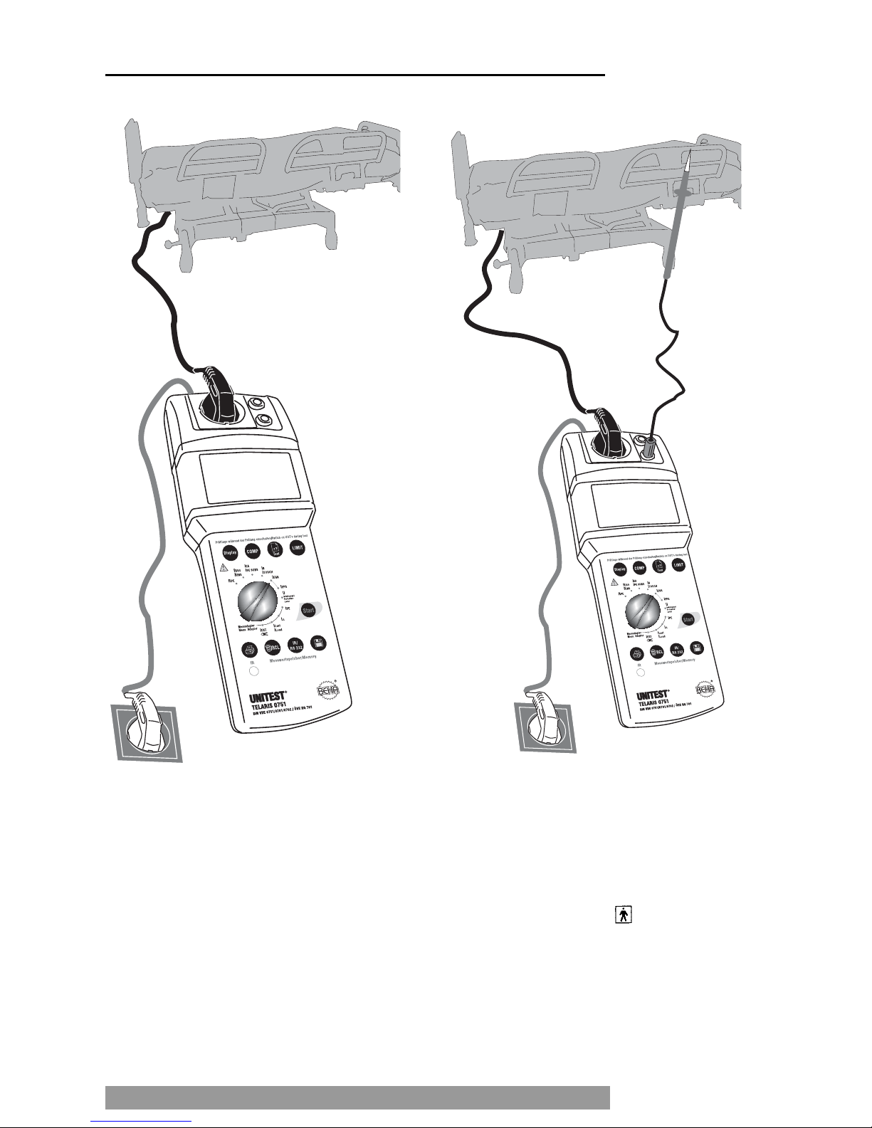
Figure 6.23: Measurement of the auxiliary instrument leakage current for instruments pertaining to
protection class I
Figure 6.24: Measurement of the auxiliary instrument leakage current for instruments pertaining to
protection class II *
* The measurement is only performed if contact
surfaces of type F are available. For this, observe
equipment designation. .
46
Measurement of the Auxiliary Instrument Leakage Current
Page 47

6.11 Measurement of the Auxiliary
Patient Leakage Current
6.11.1 General Information regarding the
Auxiliary Patient Leakage Current
According to DIN VDE 0751, Part 1:2001-10, the
measurement of the auxiliary patient leakage current is an alternative measurement procedure to determine the leakage current.
Measurement is made of the auxiliary leakage current between short-circuited mains connectors
(L/N) and the patient connectors of the respective
contact surface. For instruments pertaining to protection class I, the PE connector is connected to the
mains input, in addition. Please refer to Figure 6.25.
For instruments equipped with an internal power
supply, the auxiliary patient leakage current is measured between the casing (or touchable, conductibe parts) and the patient connectors of the respective contact surface, please refer to Figure Bild
6.26.
During the measurement of the auxiliary patient leakage current, all switches of the UUT
must be switched on, so that the complete current circuit and all insulations can be sampled
during the measurement.
Prior to performing any auxiliary patient leakage current measurement, ensure that the UUT
is not live.
Figure 6.25: Measurement of the auxiliary patient leakage current, block diagram
Figure 6.26: Measurement of the auxiliary patient leakage current for instruments equipped with an
internal power supply, block diagram
Remarks: MD is a measurement layout in compliance with DIN VDE 0750, Part 1, EN 60601-1
47
Measurement of the Auxiliary Patient Leakage Current
Page 48

6.11.2 Measurement of the Auxiliary Patient
Leakage Current (IEPA)
Performing the measurement:
Connect the UNITEST TELARIS 0751 via the
mains plug (1) to a functional and correct wired
and grounded mains socket.
Turn the ‘Measurement function” selection
switch (15) to position ‘IEPA’.
Set the limit for the insulation resistance using
the key LIMIT(7); for the limit values, please
refer to table 35, page 49.
Plug the UUT mains plug into the test socket
(3), please refer to Figure 6.23.
Switch on the UUT.
Press the key “Start” (9). The unit symbol
which is blinking on the display is an indication
for the active measurement procedure.
Read the measurement value from the LC dis-
play (6). The symbol ‘LIMIT’ (21) indicates an
exceeding of the limit values, if the limit value
display is switched on.
Continue the test of the auxiliary patient leaka-
ge current connectors of the UUT.
The measurement results can be saved by
pressing the key “Store” (10). For references
regarding the saving of measurement values,
please refer to section 7.1 and 7.2.
Figure 6.27: Measurement of the auxiliary patient leakage current
z.B. Heizdecke,
Bewegungsschiene
48
Measurement of the Auxiliary Patient Leakage Current
Page 49

Table 5: Limit values for the auxiliary leakage current
Source: Table F.1 of DIN VDE 0751, Part 1:2001-10
49
Measurement of the Auxiliary Patient Leakage Current
Leakage current in mA in mA
Contact surface TYP B TYP BF
Auxiliary instrument leakage current
- within protective earth conductor or parts
connected to the protective earth 1.0 1,0
- Instruments with mineral insulation and instruments
in compliance with remark 1 5,0 5,0
- in compliance with remark 2 10.0 10-0
Mobile X-ray instruments with 5.0 5.0
additional protective earth
Mobile X-ray instruments without additional protective earth 2.0 2.0
Auxiliary patient leakage current - 5.0
REMARK 1: instrument systems which are not equipped with the touchable parts that are not connected with
the protective earth conductor and which are in compliance with the requirements for instrument leakage current, and, if applicable, for the patient leakage current.
Example: Electronic data processing devices with shielded power supply.
REMARK 2: Instruments destined for fixed connection and which are equipped with a protective earth conductor being connected in such a way or being mechanically secured in a certain place that it can only be removed using tools.
Examples for such instruments are:
- the main components of an x-ray system such as the x-ray generator, the table for medical examination.
- Instruments equipped with mineral-insulated heating elements.
- Instruments showing superior ground leakage current values than the admissible values in
Ground Leakage Current, in general" due to the requirement to meet radio protection conditions.
REMARK 3: Mobile x-ray instruments and mobile instruments with mineral insulation.
Page 50

7.0 Storing, Printing
and Data Transfer
After every completed measurement, the user has
the possibility to save the measurement result by
pressing the key “Store” (10). Altogether, 600 individual measurement results (deducting the entered
UUT numbers) may be saved. This equals approximately 150 appliance measurements.
After the saving process, it is possible to view the
last saved measurement result and to print a report
containing the measurement results using the protocol printer (option Cat. No. 1196).
If desired, the data may be transferred via a serial
interface to a PC for the reporting using the software
es control 0701/0702 (option Cat. No. 1252).
7.1 Entering the UUT Number
The key “ NEW TEST”(8) is used to create a new UUT
number. All following measurements are assigned
to the new UUT. Every UUT number occupies also
one memory location.
Briefly pressing the key “NEW TEST” (8) dis-
plays the current UUT number. This number is
set to 001 after having deleted the memory or
at appliances.
When pressing the key " NEW TEST” (8) for a
longer time, a new UUT is created. The UUT
number is increased by one( 002, 003...).
If no measurement data has been saved since
the last UUT number entry, the entry of a new
UUT number is ignored. No new UUT number
will be created. It is impossible to save two subsequent UUT numbers without having performed any tests.
7.2 Saving Measurement Data
To save the measurement data, please proceed as
follows:
Perform a measurement.
Store the measurement result by pressing the
key “Store” (10). This is also possible during
active measurement, whereby the measurement will not be interrupted.
After successful saving, a brief signal is audi-
ble and the symbol "M” (28) is displayed, followed by the brief display of the continuous
memory location number.
If the memory is full and the key “Store” (10) is
pressed, the symbol "M" (10) is briefly displayed and
an error signal is audible.
The saved data is kept in the memory even
when the appliance is switched off.
It is not possible to save a measurement value
twice!
Under certain unfavourable conditions, data
may be lost or modified with any electronic
memory. The company CH. BEHA GmbH will
not be held responsible, neither for financial
nor for any other losses caused by data loss,
incorrect handling, or any other reason.
We highly recommend to perform a daily
measurement data transfer to a PC and to
save the data. The measurement data within the measurement appliance might be lost
by unforeseeable and exterior influences
(drop, electro-magnetic influence, etc.).
50
Storing, Printing and Data Transfer
Page 51

7.3 Viewing Measurement Data
Respectively, the last measurement value can be
displayed.
To view measurement data, please proceed as follows:
Briefly press the key “Clear/Recall” (13). The
last memory location number is displayed.
After this, the measurement data and the pre-
selected limit values are displayed for approx.
3 seconds.
If a number (e.g. 12) is displayed in lieu of a
measurement value, this indicates that a UUT
number has been stored at the last memory location and no measurement has been stored
hereafter.
Attention, extended pressing (longer than 2s)
of the key “Clear/Recall” (13) causes the last
measurement value to be deleted.
7.4 Printing Measurement Data
After having saved the measurement result, it is
possible to print a report containing the measurement results. For this, the UNITEST Protocol Printer (Cat. No. 1196) and the Interface Adapter (Cat.
No. 1157) are required (option).
As desired, the saved measurement data for the last
UUT or for all UUTs may be printed.
To print the measurement data, please proceed as
follows:
Perform the desired measurements and save
these measurements by pressing the key
“Store” (10), please refer to section 7.1 and 7.2.
Apply the TELARIS Interface Adapter (Cat. No.
1157) onto the TELARIS 0751.
Connect the serial connection cable with the
protocol printer.
Switch on the printer and set the interface pa-
rameter on the protocol printer in compliance
with the TELARIS 0751 (9600 Baud, 8 data bit,
1 Stopbit, no parity).
To print out the saved measurement values of
the last UUT, briefly press the key “Print” (14).
"Prt” is displayed on the screen. The data is
transferred to the protocol printer. During the
printing process, the number of the memory locations remaining for printing is indicated as
countdown.
To print all saved measurement values, press
the key “Print” (14) slightly longer (approx. 2
seconds). "Prt” is displayed and the data is
transferred to the protocol printer. During the
printing process, the number of the memory locations remaining for printing is indicated as
countdown.
The printing of more than 10 data records can
be cancelled by pressing the key “Print” (14).
For this, press the key “Print” (14) after the
printout of the 10th data record. Leave the key
depressed until the printout is cancelled.
Imperatively observe the interface settings of
the protocol printer and accordingly set the interface parameter of the TELARIS 0751 (9600
Baud, no parity, 8 data bit, 1 stop bit, please
refer to the technical data section). Please refer
to the instruction manual supplied with the protocol printer (Cat. No. 1196) for printer parameter setting.
51
Viewing Measurement Data/Printing Measurement Data
Page 52

7.5 Deleting Saved Measurement
Data/View the Memory Location Number
It is possible to delete the last measurement value
or all measurement values by pressing the key
"Clear/Recall” (13). Furthermore, it is possible to
display the memory location number of all saved
measurement values and UUT numbers:
7.5.1 Display of Memory Location Number (total
number of saved measurement data and
UUT numbers):
Briefly press the key “Clear/Recall” (13). An
acoustic signal is audible.
The last memory location number is briefly dis-
played, followed by the display of the saved
measurement results and limit values.
7.5.2 Delete Last Saved Measurement Value:
Press the key “Clear/Recall” (13) and keep it de-
pressed.
An acoustic signal is audible and the last mem-
ory location number is briefly displayed. Afterwards, the measurement value or the UUT number saved at this memory location is displayed
Press the key “Clear/Recall” (13) further until
"Clr” is displayed on the screen and the displayed memory location number is reduced by
one. A further acoustic signal is simultaneously audible.
Now release the key “Clear/Recall” (13) to avoid
deletion of the complete memory.
Deleting the last saved measurement value or
last entered UUT number can be repeated as
desired, i.e. as long as data is available within
the memory.
7.5.3 Delete all Saved Measurement Values:
Press the key “Clear/Recall” (13) and keep it depressed.
An acoustic signal is audible and the last mem-
ory location number is briefly displayed. Afterwards, the measurement value or the UUT number saved at this memory location is displayed
A beep signal is audible after 2 sec. and the last
stored value is deleted.
A beep signal is audible after 2 sec. and all
stored values are deleted.
“0“ appears on the LC-display. The memory is
completely deleted, the „M" symbol in the display disappears.
52
Deleting Saved Measurement Data/View the Memory Location Number
Page 53

7.6 Infrared Interface, send Measurement Data
Additionally, all stored measurement data may be
transferred to the PC (for reporting) by the Infrared
Interface. For this purpose, the interface adapter
and the Software "es control 0701/0702” (Cat. No.
1252) and Interface (Cat. No. 1157), available as an
optional feature, are required.
The data transfer procedure is fairly easy:
Carry out measurements and save theses by
pressing key “Store” (10), see also section 7.1
and 7.2
Apply the Interface adapter (Cat. No. 1157) to
TELARIS 0751.
Connect interface cable via 9pole D-sub con-
nector to serial interface of PC (ie COM 1).
Call the "es control 0701/0702” Software
(please refer to user manual "es control 0751”).
Data transfer is carried out. After a succesfull
data transfer all stored data is available for further processing in the PC.
8.0 Maintenance
When using the appliance in compliance with the instruction manual, no special maintenance is required.
8.1 Cleaning
If the appliance is dirty after daily usage, it is advised
to clean it by using a damp cloth and a mild household detergent.
53
Infrared Interface, send Measurement Data / Maintenance / Cleaning
Page 54

9.0 Internal fuses
The internal fuses protects the appliance from
overload or wrong operation/use.
The fuses are inside the appliance, the instrument
must be opened for the exchange.
The fuses can only be replaced by returning the
appliance to the factory or to an authorized sales
repair service.
Exclusively use fuse of the same voltage, current and breaking capacity values in compliance with the technical data section.
9.1 Display after Fuse Blown
If the appliance TELARIS 0751 displays the measurement values described below during the measurement, the respective fuse has blown.
The fuse must be replaced and the instrument
must be checked afterwards. For this, return
the measurement appliance to the factory.
No function and display of the appliance when plugging into a functional mains socket:
- Fuse F1 has blown.
For the "RPE” Function:
Display >20.0 Ohm in spite of direct connection between "Probe” (2) and the PE of the test socket (3)
or the blue socket "PE” (5):
- Fuse F2 has blown.
For the "IPE SUBS” function:
Display <0.20 mA in spite of direct short-circuit of
the blue socket "PE” (5) and the red socket "L/N” (4):
- Fuse F2 has blown.
9.2 Description of the built-in Fuses
Fuse F1 (built-in)
Type F 0.1 A/250 V, 5 x 20 mm
Mains input fuse
Fuse F2 (in fuse housing within the appliance rear)
Type F 0.5 A/250 V, 6.3 x 32 mm.
Input fuse for the measurement circuits RPE (PE resistance) and IPE SUBS (substitute leakage current)
10.0 Calibration Interval
We suggest a calibration interval of one year. If the
instrument is used very often or if it is used under
rough conditions we recommend shorter intervals. If
the instrument is used few times only the calibration
interval can be extended on to 3 years.
54
Internal fuses/Display after Fuse Blown/Calibration Interval
Page 55

11.0 Technical Data
Function PE resistance (RPE)
according to EN 61557-4, DIN VDE 0413, Part 4,
Display range:..................................0.05 Ω... 19.99 Ω
Measurement range:........................0.1 Ω ... 1.99 Ω
Resolution: ......................................0.01 Ω
Accuracy: ........................................± (10% rdg. + 3 Digits)
Limit value: ......................................0.3 Ω and 1.0 Ω
Test current: ....................................≥ 200 mA AC/50 Hz, at 2 Ω
Test voltage: ....................................approx. 19.0 V AC
Measurement time:..........................continous
Function Insulation resistance (RINS)
according to EN 61557-2, DIN VDE 0413, Part 2
Display range:..................................0.1 MΩ ... 250 MΩ
Measurement range:........................0.1 MΩ ... 199.9 MΩ
Resolution: ......................................0.01 MΩ/ 0.1 MΩ/1 MΩ
Accuracy: ........................................± (10% rdg. + 3 Digits)
Limit value: ......................................0.25/0.3/0.5/1.0 and 2.0 MΩ
Test voltage: ....................................500 V DC (DC)
........................................................+ 50 % / – 0 % (according to EN 61557-2)
Nominal current:..............................> 1 mA at 500 kΩ Load resistance
Short circuit current:........................approx. < 4 mA
Measurement time ..........................approx. 2 Min.
Function Leakage Current IPE SUBS
according to DIN VDE 0701/0702, Part 1
Display range:..................................0.20 mA ... 19.99 mA
Measurement range:........................0.25 mA ... 19.00 mA
Resolution: ......................................0.01 mA
Accuracy: ........................................± (10% rdg. + 3 Digits)
Limit value: ......................................0.5/ 3.5/7 and 15 mA
Test voltage: ....................................< 50 V AC. 50 Hz
Short circuit current:........................< 3.5 mA
Measurement time:..........................continous
The display values are according DIN VDE 0702:1995-11 refering to a mains voltage of 230 V +6%, (244 V).
55
Technical Data
Page 56

Function Touch current ILEAK
according to DIN VDE 0701/0702, Part 1
Display range:..................................0.01 mA … 1.999 mA
Measurement range:........................0.1 mA … 1.99 mA
Resolution: ......................................0.001 mA
Accuracy: ........................................± (10% rdg. + 3 Digits)
Limit value: ......................................0.25 and 0.5 mA
Internal resistance: ........................approx. 2 kΩ
Crestfactor:......................................< 4
Frequency range: ............................0...100 kHz
Frequence response:........................according circuit A1, EN 61010-1
Substitute housing leakage current (IEGA)
according DIN VDE 0751, Part 1
Display range:..................................0,20 mA ... 19,99 mA
Measurement range ........................0,25 mA ... 19,00 mA
Resolution: ......................................0,01 mA
Accuracy: ........................................± (10% v.M. + 3 Digits)
Limit value: ......................................1,0/ 2,0/5,0 und 10 mA
Test Voltage: ....................................< 50 V AC, 50 Hz
Short Circuit Current: ......................< 3,5 mA
Measurement Time..........................continous
The display values are according DIN VDE0751 2001-10 refering to a mains voltage of 230 V.
Substitute patient leakage current (IEPA)
according DIN VDE 0751, Part 1
Display range ..................................0,20 mA ... 19,99 mA
Measurement range ........................0,25 mA ... 19,00 mA
Resolution: ......................................0,01 mA
Accuracy: ........................................± (10% v.M. + 3 Digits)
Limit value: ......................................5,0 mA
Test Voltage: ....................................< 50 V AC, 50 Hz
Short Circuit Current: ......................< 3,5 mA
Measurement Time..........................continous
The display values are according DIN VDE0751 2001-10 refering to a mains voltage of 230 V.
56
Technical Data
Page 57

Function Protection Level of overvoltage devices (VProt Level)
Display rangee: ................................50 ... 500 V (DC)
........................................................31 ... 312 V (AC)
Calculation:......................................UAC=UDC/1.6
Measurement range:........................50 ... 500 V DC
Resolution: ......................................1 V
Accuracy: ........................................± (10% rdg. + 3 Digits)
Test voltage: ....................................approx. 500 V DC
Test current: ....................................> 1 mA
Measurement time:..........................approx. 15 Seconds
Function PE resistance Current IPE and Differential Current IΔ
according to DIN VDE 0701/0702, Part 1
with Schuko Measurement Adapter (option)
Display range:..................................0.1 mA … 19.99 mA
Measurement range:........................0.25 mA … 19.00 mA
Resolution: ......................................0.01 mA
Accuracy: ........................................± (5% rdg. + 3 Digits)
Limit value: ......................................3.5 mA
Frequency range: ............................40 Hz...100 kHz
Crestfaktor:......................................< 4
Function Load Current ILoad
with Schuko Measurement Adapter (option)
Display range:..................................0.1 A … 16.00 A
Measurement range:........................0.1 A … 16.00 A
Resolution: ......................................0.01 A
Accuracy: ........................................± (5% rdg. + 3 Digits)
Frequency range: ............................45 Hz...65 Hz
Crestfaktor:......................................< 4
Function External Current Measurement (IEXT)
with Current Clamp Adapter (option)
(Technical data refering to measurement input only)
Display range:..................................0.25 mA … 19.99 mA
Measurement range:........................0.25 mA … 19.00 mA
Resolution: ......................................0.01 mA
Accuracy: ........................................± (5 % rdg. + 3 Digits)
Limit value: ......................................3.5 mA
Frequency range: ............................45 Hz...65 Hz
Crestfaktor:......................................< 4
57
Technical Data
Page 58

General Technical Data
Display:............................................31/2-digit. LC-Display
Temperature Ranges
Reference Temperature Range:........+23 °C (± 2 °C), 40...60 % rel. humidity
Working Temperature: ....................0 °C ... + 40 °C, max. 85 % rel. humidity (not condensing)
Storage Temperature: ......................–20 °C ... + 60 °C, max. 85 % rel. humidity (not condensing)
Memory: ..........................................600 values, approx. 150 tests
(at 3 measurements each EUT)
Interace: ..........................................Infrared RS 232
Parameter: ......................................9600 Baud, 8 data bit, 1 stop bit, no parity
Protection degree: ..........................IP40
Protection Class:..............................II
Built according to:............................DIN VDE 0411, Part 1, EN 61010-1,
........................................................DIN VDE 0404, Part 1, 2
........................................................DIN VDE 0413, Part 1,2,4
........................................................DIN VDE 0701/0702
External Voltage withstanding: ........300 V AC/DC (continous)
........................................................600 V AC/DC (1 min at Insulation measurement )
Over Voltage Category: ....................CAT II/300 V
Pollution Degree: ............................2
Power Supply: ................................230 V +10 % - 15 %, 50 Hz (± 1%)
Power Consumption: ......................max. 15 VA
Built in fuses: ..................................F1: Type F 0.1 A/250 V. 5 x 20 mm
........................................................F2: Type F 0.5 A/250 V, 6.3 x 32 mm
Dimensions: ....................................300 x 105 x 75 mm (W x H x D)
Weight: ............................................approx. 1.3 kg
58
Technical Data
Page 59

Schuko-Measurement Adapter (Option)
Measurement Functions: Earth Current, Differential Current, Load Current
Output: 0...1 V AC
Function Earth Current and Differential Current
Display Range: ................................0.25 mA … 19.00 mA
Measurement range:........................0.25 mA … 19.00 A
Accuracy: ........................................± (5% rdg. + 50 µA)
Frequency Range: ............................40 Hz...100 kHz
Frequency response:........................according. circuit A1, IEC610010-1
Function Load Current
Display range:..................................0.1 A … 19.99 A
Measurement range:........................0.1 A … 16.00 A
Accuracy: ........................................± (5% rdg. + 0,03 A)
Frequency Range: ............................45...65 kHz
Output Current:................................max. 16 A
Switch on time:................................max. 30 min (at 16 A)
General Technical Data
Reference Temperature Range:........+23 °C (± 2 °C), 40...60 % rel. humidity
Working Temperature: ....................0 °C ... + 40 °C, max. 85 % rel. humidity (not condensing)
Storage Temperature: ......................–20 °C ... + 60 °C, max. 85 % rel. humidity (not condensing)
Protection degree: ..........................IP40
Protection class: ..............................II
Built according to:............................EN 61010-1, DIN VDE 0411, Part 1, DIN VDE 0404, Parts 1, 2
........................................................DIN VDE 0701/0702
Over Voltage Category: ....................CAT II/300 V
Pollution degeree:............................2
Power Supply: ................................230 V +10 % - 15 %, 50 Hz (± 1%)
Power Consumption: ......................max. 5 VA
Built in fuses: ..................................F1: Type T 0,2 A/250 V, 5 x 20 mm
Dimensions: ....................................200 x 100 x 50 mm (W x H x D)
Weight: ............................................approx. 600 g
59
Technical Data
Page 60
60
24 Month Warranty
Die BEHA-Gruppe bestätigt
hiermit, dass das erworbene
Produkt gemäß den festgeleg-
ten Beha Prüfanweisungen
während des Fertigungspro-
zesses kalibriert wurde. Alle
innerhalb der Beha-Gruppe
durchgeführten, qualitätsrelevanten Tätigkeiten und Prozesse werden permanent durch
ein Qualitätsmanagements-
ystem nach ISO 9000 überwacht.
Die BEHA-Gruppe bestätigt
weiterhin, daß die während der
Kalibrierung verwendeten Prüf
einrichtungen und Instrumente
einer permanenten Prüfmittelüberwachung unterliegen. Die
Prüfmittel und Instrumente
werden in festgelegten Abständen mit Normalen kalibriert,
deren Kalibrierung auf nationale und internationale Standards
rückführbar ist.
The BEHA Group confirms
herein that the unit you have
purchased has been calibrated,
during the manufacturing
process, in compliance with
the test procedures defined by
BEHA. All BEHA procedures
and quality controls are monitored on a permanent basis in
compliance with the ISO 9000
Quality Management Stan-
dards.
In addition, the BEHA Group
confirms that all test equipment and instruments used during the calibration process are
subject to constant control. All
te
st equipment and instruments used are calibrated at
determined intervals, using reference equipment which has
also been calibrated in compliance with (and traceable to)
the calibration standards of
national and international labo-
ratories.
Le groupe BEHA déclare que
l´appareil auquel ce document
fait référence a été calibré au
cours de sa fabrication selon
les procédures de contrôle définies par BEHA. Toutes ces
procédures et contrôles de
qualité sont régis par le systéme de gestion ISO 9000.
Le groupe BEHA déclare par
ailleurs que les équipements de
contrôle et les instruments
utilisés au cours du processus de
calibrage sont eux-mêmes
soumis à un contrôle technique
permanent.
Ces mêmes équipements de
contrôle sont calibrés régulièrement à l´aide d´appareils de
référence calibrés selon les directives et normes en vigueur
dans les laboratoires de recherche nationaux et internationaux.
El grupo BEHA declara que el
producto adquirido ha sido calibrado durante la producción
de acuerdo a las instrucciones
de test BEHA. Todos los proce-
sos y actividades llevados a ca-
bo dentro del grupo BEHA en
relación con la calidad del producto son supervi
sados permanentemente por el sistema
ISO 9000 de control de calidad.
Adicionalmente, el grupo BEHA
constata que los equipos e ins-
trumentos de prueba utilizados
para la calibración también son
sometidos a un permanente
control. Estos equipos e instru-
mentos de prueba son a su vez
calibrados en intervalos regulares valiéndose de equipos de
referencia calibrados de acuerdo a directivas de laboratorios
nacionales e internacionales.
쮕
IQ NET
AENOR Spain AFAQ France AIB-Vincotte Inter Belgium APCER Portugal BSI United Kingdom CSIQ Italy
CQS Czech Republic DQS Germany DS Denmark ELOT Greece FCAV Brazil IRAM Argentina JQA Japan
KEMA Netherlands KSA-QA Korea MSZT Hungary NCS Norway NSAI Ireland ÖQS Austria PCBC Poland PSB Singapore
QAS Australia QMI Canada SFS Finland SII Israel JQA Japan SIQ Slovenia SIS-SAQ Sweden SQS Switzerland
IQNet is represented in the USA by the following IQNet members: AFAQ, AIB-Vinçotte Inter, BSI, DQS, KEMA, NSAI and QMI
Qualitätszertifikat • Certificate of Quality
Certificat de Qualité • Certificado de calidad
Page 61

24 month Warranty
UNITEST appliances are subject to strict quality control. However, should the appliance function improperly during daily use, you are protected by our 24
months warranty (valid only with invoice).
We will repair free of charge any defects in workmanship or material, provided the appliance is returned unopened and untampered with, i.e. with undamaged warranty label.
Any damage due to dropping or incorrect handling
are not covered by the warranty.
If the appliance shows failure following expiration of
warranty, our service department can offer you a
quick and economical repair.
61
Page 62

62
Page 63

63
Page 64
64
CH. BEHA GmbH
Elektronik · Elektrotechnik
In den Engematten 14
79286 Glottertal/Germany
Tel.: +49 (0) 76 84/80 09-0
Fax: +49 (0)76 84/80 09-410
Techn. Hotline: +49 (0)76 84/80 09-429
internet: http://www.beha.com
e-mail: info@beha.de
Reg.No. 3335
03/2006 Subject to technical changes without notice! PTEB90950001
 Loading...