

United States Stove Company Logwood 1261 Owner's Manual
Owners Manual
W
a
r
n
o
c
k
H
e
r
s
e
y
I
N
T
E
R
T
E
K
US
Logwood 1261
EPA EXEMPT PER
METHOD 28A
TESTED TO
UL 1482
CAUTION!
Read All Instructions Carefully
Before Starting The Installation
or Operating This Heater.
SAVE THIS MANUAL FOR FUTURE REFERENCE
THIS MANUAL WILL HELP YOU TO OBTAIN EFFICIENT, DEPENDABLE SERVICE FROM THE HEATER, AND ENABLE YOU
TO ORDER REPAIR PARTS CORRECTLY. KEEP IN A SAFE PLACE FOR FUTURE REFERENCE.
DO NOT USE THIS HEATER
IN A MOBILE HOME OR TRAILER
UNITED STATES STOVE COMPANY
227 Industrial Park Road
P.O. Box 151
South Pittsburg, TN 37380
(423) 837-2100
-1-
85029F
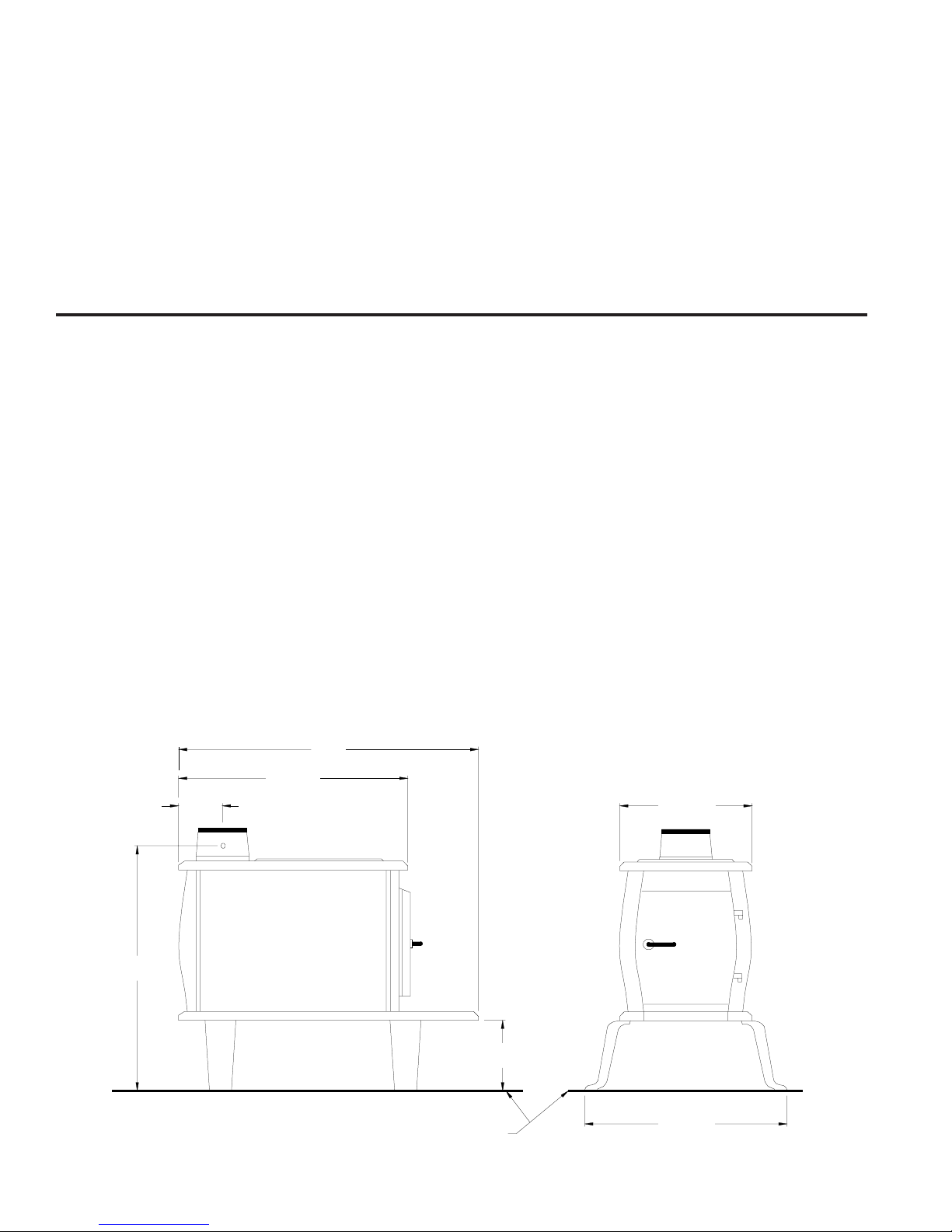
33"
4-5/8"
23"
FLOOR PROTECTOR
11-3/8"
18-1/2"
26-1/2"
8"
CONGRATULATIONS!
You've purchased a heater from North America's oldest manufacturer of wood burning products.
By heating with wood you're helping to CONSERVE ENERGY!
Wood is our only Renewable Energy Resource. Please do your part to preserve our wood supply.
Plant at least one tree each year. Future generations will thank you.
Tools and Materials Needed
TOOLS
Pencil
6 Foot Folding Rule or Tape Measure
Tin Snips
Drill, Hand or Electric
Drill Bit 1/8" Dia. (For Sheet Metal Screws)
Adjustable Wrench
Screw Driver (Blade-Type)
Gloves
Safety Glasses
MATERIALS
6" Elbow, Collar and Thimble; As Required
(24 gauge min.)
1/2" Sheet Metal Screws (No. 10A x 1/2")
6" Diameter, 24 gauge, black or blued steel
Underwriters Laboratories UL Listed
Residential Type HT (2100°F) Chimney or use a
Masonry Chimney in good repair.
Floor Protector Material (R value = 2.0); Size and
Installation as specied on Page 4
Furnace Cement (Manufacturer Recommends:
Rutland Black Code 78 or Equivalent)
6" Barometric Draft Regulator (DR-6)
HEATER DIMENSIONS
FIG. 1
-2-

Safety Rules
SAFETY NOTICE: If this heater is not properly installed a house re may result. For your safety, follow the in-
stallation directions. Contact local building or re ofcials about restrictions and installation inspection requirements in your area.
Read these rules and the instructions carefully.
1. Check with local codes. The installation must comply with
their rulings. Observe closely the clearances to combustibles
(page 4).
2. Do not install this heater in a mobile home or trailer.
3. Always connect this heater to a chimney and vent to the
outside. Never vent to another room or inside a building.
4. Do not connect a wood burning heater to a Type B gas
vent. This is not safe and is prohibited by the National Fire
Protection Association Code. This heater requires approved
masonry or UL Listed Residential Type and Building Heating
Appliance Chimney. Use a 6" diameter chimney, or larger,
that is high enough to give a good draft.
5. Be sure that your chimney is safely constructed and in good
repair. Have the chimney inspected by the Fire Department
or a qualied inspector. Your insurance company may be
able to recommend a qualied inspector.
6. Inspect chimney connector and chimney twice monthly
during the heating season for any deposit of creosote or
soot which must be removed (see Chimney Maintenance,
page 9).
9. For further information on using your heater safely, obtain
a copy of the National Fire Protection Association (NFPA)
publication "Using Coal and Wood Stoves Safely" NFPA
No. HS-10-1978. The address of the NFPA is Batterymarch
Park, MA 02269.
10. Disposal of Ashes - Place ashes in a metal container with a
tight tting lid. Keep the closed container on a noncombustible oor or on the ground, well away from all combustible
materials. Keep the ashes in the closed container until all
cinders have thoroughly cooled. The ashes may be buried
in the ground or picked up by a refuse collector.
11. CAUTION - The special paints used on your heater may
give off some smoke while they are curing during the rst
few res. Build small res at rst.
12. CARING FOR PAINTED PARTS - This heater has a painted
jacket which is durable but it will not stand rough handling
or abuse. When installing your heater, use care in handling.
Clean with soap and warm water when heater is not hot.
DO NOT use any acids or scouring soap, as these wear
and dull the nish. PAINT DISCOLORATION WILL OCCUR
IF THE HEATER IS OVERFIRED. FOLLOW OPERATING
INSTRUCTIONS CAREFULLY.
7. Provide air for combustion from outside the house into the
room where the heater is located. If the intake is not in the
same room, air must have free access in to the room.
8. To prevent injury, do not allow anyone to use this heater
who is unfamiliar with the correct operation of the heater.
13. All persons, especially children, should be alerted to hazards from high surface temperatures and kept away while
in operation. Small children should not be left unsupervised
when in the room with the heater.
14. Keep the area adjacent to the heater free from all combustible materials, gasoline, and other ammable vapors.
CAUTION! Do not touch the heater until it has cooled.
NOTE:
FOR YOUR SAFETY, WE RECOMMEND INSTALLING SMOKE DETECTORS IN YOUR HOME IF NOT ALREADY
INSTALLED.
-3-
Installation
Place the heater on solid masonry or solid concrete. When the
heater is used on a combustible oor, use an Underwriters Listed
oor protector. The oor protector must comply with UL Standards.
The base should extend at least 16" beyond the door side of
the heater and should extend under the ue pipe if it is elbowed
towards a wall. (Fig. 5).
1. Uncrate and/or unpack the heater, removing all packing material, being careful not to dispose of the Parts Bag.
2. Open the front feed door and remove the parts from inside the
stove. You should nd the following: Hearth Plate (1); Solid
Damper (1); Lids (2); Pivoting Top (1); Lid Support (1); Parts
Package (1) containing nuts, bolts, door handle, door latch
and securing hardware; Legs (4); Cast Iron Collar (1); Cast
Iron Damper (1); Bafe Assembly (1); Lid Lifter (1).
3. Place cardboard or other soft material adjacent to the stove
and carefully turn the stove onto its top side (bottom facing
up).
4. Attach hearth plate to the front of the stove in its proper location.
5. Attach both rear and front legs to the stove. Tighten the nuts
and bolts securely. The stove may now be CAREFULLY
turned over to stand on it's four legs.
6. Attach the bafe assembly and ue collar to the stove by
inserting the bafe studs thru the two holes located on the
top of the rear of the stove; place the ue collar over the
studs and mount using the proper nuts and washers. Place
lid support and lid in position on pivoting top. Place the slide
damper in position on the top of the hearth plate and under
the feed door, and secure with screw in slot.
7. After consulting the installation instructions for minimum clear-
ances to combustibles, locate your oor protector accordingly
and carefully place the stove in your selected location. Install
stove pipe, elbows and thimble as necessary, utilizing either
a recently cleaned and inspected masonry chimney (properly
lined) or a UL Listed chimney. Insure that the damper provided
is installed in the ue collar.
8. Again, check the following illustrations and be sure you have
the clearances shown from the heater and the connector pipe
to combustible surfaces. If you have a solid brick or stone wall
behind your heater, you may place your heater as close as
you wish to the wall. However, if the wall is only faced with
brick or stone, consider it a combustible wall.
9. If your chimney drafts excessively, purchase and use a Barometric Draft Regulator (DR6 available from factory).
10. The chimney connection should be as short as possible, and
the heater must have its own ue. Do not connect this unit to
a chimney ue serving other appliances.
11. Use three sheet metal screws in each stove pipe and or elbow
joint to rmly hold the pipe together.
12. Do not install this heater in a mobile home or trailer.
13. Check your local building and insurance codes. The installation must comply with their rulings.
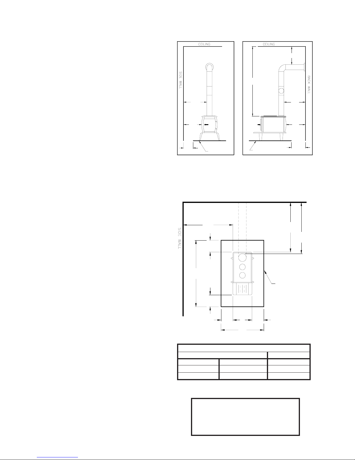
MINIMUM CLEARANCE
TO COMBUSTIBLE WALLS
18"
458mm
(60"
MIN.)
34"
865mm
28"
712mm
37-1/2"
953mm
FIG. 2
FLOOR
PROTECTOR
FIG. 3
FLOOR
PROTECTOR
712mm
660mm
508mm
HEATER/FLOOR PROTECTOR LOCATION
(Dimensions are required for non-protected surfaces.
See chart for dimensions for protected surfaces.)
BACK WALL
DASHED LINES
SHOW STRAIGHT
OUT CHIMNEY
CONNECTOR
34"
865mm
6"
153mm
60"
16"
407mm
6"
153mm
NON- COMBUSTIBLE
CONSTRUCTION IN
ACCORDANCE WITH
NFPA 211
28"
FIG. 4
660mm
FLOOR
PROTECTOR
6"
153mm
26"
Protected Surfaces (NFPA 211)
Parallel Corner
Side Rear
12-inches 12-inches 12-inches
305-mm 305-mm 305-mm
28"
26"
20"
28-3/4"
730mm
CAUTION!
KEEP FURNISHINGS AND OTHER
COMBUSTIBLE MATERIALS
AWAY FROM THE HEATER.
-4-
 Loading...