

United States Stove Company 1602M Installation And Operator's Manual
Installation/Operator’s Manual
Model: 1602M
Wood or Coal Gravity Style (Up-Flow) Supplemental Furnace
Certified to comply with 2015 particulate emissions standards.
If this furnace is not properly installed, a house fi re may result! For your safety, follow these installation instructions.
Contact local building or fi re offi cials about restrictions and installation requirements in your area. This furnace must
be installed by a qualifi ed technician. Keep these instructions for future reference.
United States Stove Company • 227 Industrial Park Road, P.O. Box 151 • South Pittsburg, TN 37380 • www.usstove.com
U.S. Environmental Protection Agency
SAFETY NOTICE:
Safety Tested to UL 391
851767B-1905E
INTRODUCTION
Thank You for your purchase of a U.S. Stove Wood/Coal
Burning Gravity Style (Up-Flow) Furnace. Your decision
to buy our Clayton Furnace was undoubtedly reached af-
ter much careful thought and consideration. We are very
proud you chose this furnace and trust you will receive
the comfort and economy that others realize when heat-
ing with a U.S. Stove product.
Your dealer is important in your experience with the furnace not only with the purchase, but for recommendations
for professional installation in your home. The qualifi ed
professional installer has been expertly trained in solidfuel furnace installation to assure the safety and comfort
for your family while saving you money. Trust your experienced installer. He is a specialist in this fi eld.
Warning:
Do not alter this appliance in any way other than specifi ed
in these instructions. Doing so may void your warranty.
LOCATING YOUR FURNACE
The furnace is to be installed maintaining the clearances
specifi ed in the following illustrations.
Do not place the furnace directly on a combustible fl oor.
If you are placing it on a combustible fl oor, an approved
fi re retardant material, equivalent to 3/8” UL Listed millboard, should be placed under the unit. The material must
extend at least 16 inches beyond the front of the unit and
8 inches on either side of the fuel loading door opening. It
must also extend underneath the chimney connector and
to each side of the connector by at least 2 inches.
IMPORTANT
Before installing and using your Clayton furnace, please
read the following pages thoroughly and carefully. If you
follow the instructions, your Clayton furnace will give you
safe and more dependable service for years to come.
• First step: Check your local codes. This installation
must comply with their rulings.
• Do Not install this furnace in a mobile home or trailer
• Always have a smoke or ionization detector and a CO
detector installed in your home.
• To prevent injury or damage, do not allow anyone who
is unfamiliar with the furnace to operate it.
• This furnace must be installed ONLY in the prescribed
manner shown in illustrations 1, 2, or 3 under the Installation Examples in this manual. It is NEVER to be
installed as a counter-fl ow or down-draft furnace, or
in any manner wherein the heated air is directed in a
downward fl ow into the home or toward to an existing
central furnace.
• NEVER INSTALL outside the home.
• Spend adequate time with your furnace to become well
acquainted with the different settings and how each
will affect its burning patterns. It is impossible to state
just how each setting will affect your furnace because
of the variations in each installation.
DISCLAIMER NOTICE
The BTU ranges and heating capacity specifi cations are
provided as a guide and in no way guarantee the output
or capacity of this unit. The actual BTU output depends
on the type of fuel being burned and its conditions, the
thermostat setting, the draft adjustment and the chimney
to which the unit is attached. The actual area that this unit
will heat depends on factors such as the conditions of the
building, heat loss, type of construction, amount of insulation, type of air movement, the location of the unit and
more importantly the duct work and return air facility.
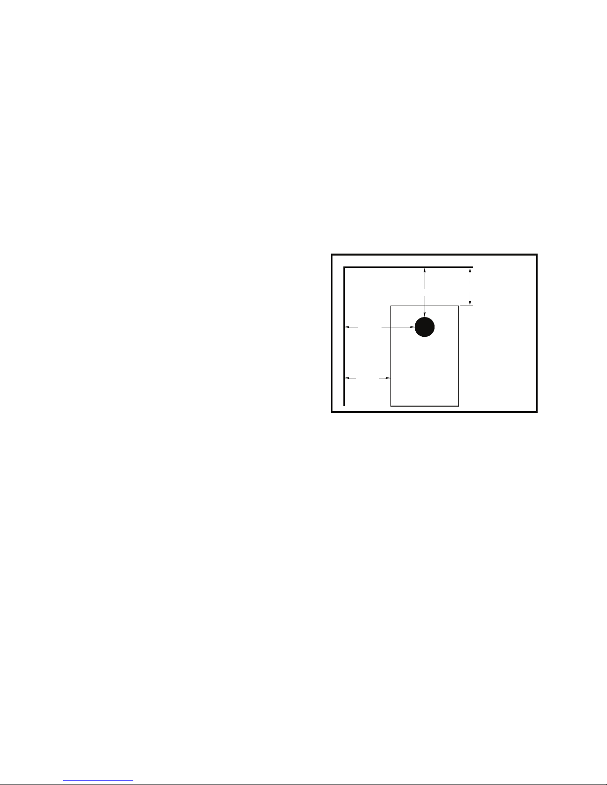
CLEARANCES
COMBUSTIBLE WALL
20”
22”
FLUE
COMBUSTIBLE WALL
12”
15”
(TOP VIEW)
MINIMUM CLEARANCES
TO A COMBUSTIBLE
WALL
CAUTION:
DO NOT store
combustible or
flammable materials or
liquids near the
furnace.
REDUCED CLEARANCES
NFPA guidelines and most codes permit reduced clearances to combustible walls and ceilings if adequate protection is added. A common mistake is to assume that
sheet metal, masonry, or millboard placed directly against
a wall protects it. Materials installed in this manner actually
provides very little protection. These materials are good
heat conductors, so they will be almost as hot on their
back side as they are on the exposed side. Therefore, the
combustible wall behind is still a fi re hazard.
A wall can be kept cool using these items but only if they
are mounted and spaced out from the wall by an inch or
two to allow free air circulation behind the protective panel.
The protective panel should also have a gap between the
fl oor and ceiling.
Three rules to follow when constructing wall protectors:
1. Non-combustibility of all materials including mounting and supporting.
2. A well ventilated air space between protector and wall.
3. Suffi cient strength and rigidity so that the protector
and air space will be durable.
2
CHIMNEY REQUIREMENTS
2 in. [5cm]
FROM CEILING
CONSTRUCTING
NON-COMBUSTIBLE
WALLS
PROTECTIVE COVERING
AND ALL SUPPORTS MUST
BE NON-COMBUSTIBLE
1. The furnace should be the only heating using the chimney fl ue. One furnace per fl ue outlet.
2. A masonry chimney should have a tile or stainless steel
liner.
3. The masonry chimney should not have any missing
mortar or loose bricks.
4. There should be no mortar or parts of the chimney
blocking the chimney fl ue.
1 in [2.5cm]
AIR SPACE
2 in [5cm]
FROM FLOOR
A fi reclay lined masonry or Class A 103HT All-Fuel Metal
Insulated Chimney must be used in all airtight wood furnace installations. The minimum recommended fl ue size
for the model 1602 is 6 inches, inside diameter. When
making new chimney installations, always follow the chimney manufacturer’s instructions.
If at all possible, use the factory built, class A 103HT chimney mentioned above. They are safer and perform better
than traditional masonry chimneys. If a masonry chimney is a must, be certain it has a fi re clay liner and that
it is intact, clean and recently inspected. And remember,
masonry chimneys are far more prone to the formation of
hazardous creosote.
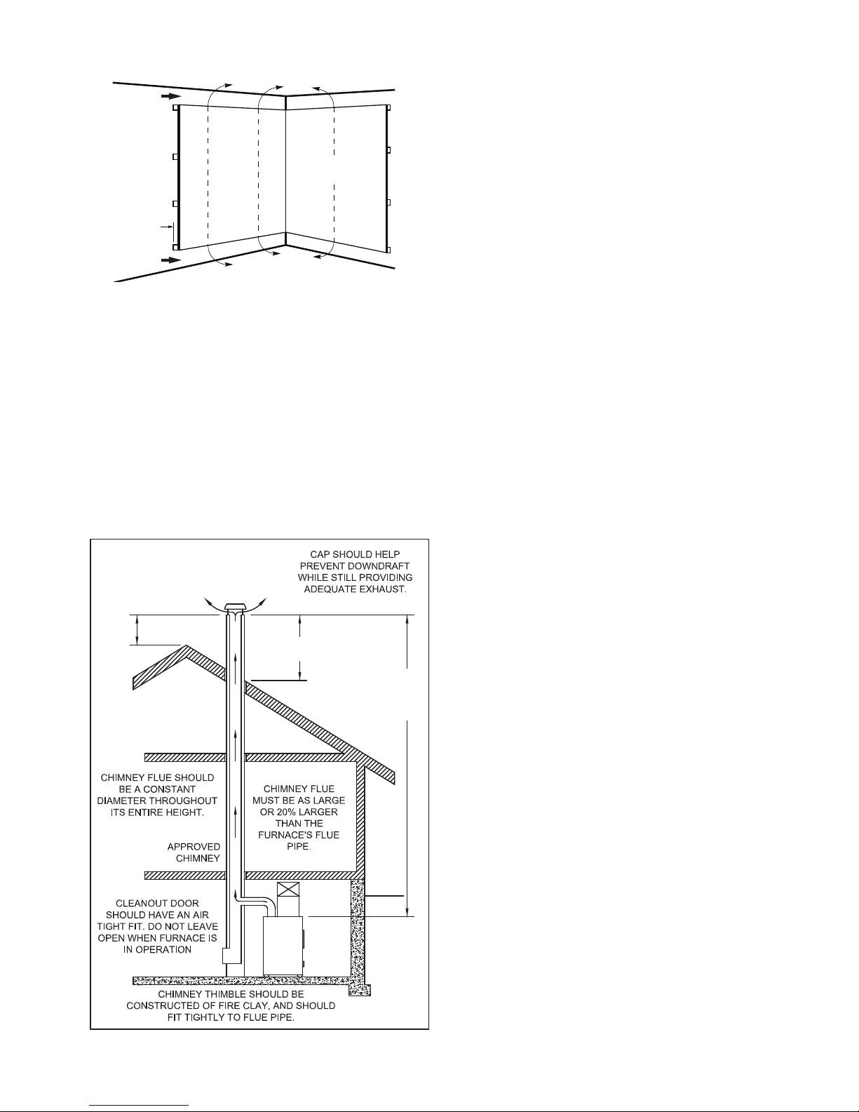
TOP OF CHIMNEY MUST BE
2 FEET [61cm] ABOVE
HIGHEST POINT OF THE
ROOF WITHIN 10 FEET
[305cm].
2 FT [61cm]
MINIMUM
MINIMUM 3 FT[91cm] FROM
TOP OF CHIMNEY TO
POINT AT WHICH IT
PASSES THROUGH THE
ROOF.
3 FT [91cm]
MINIMUM
RECOMMENDED
MINIMUM HEIGHT
20 FT [610cm]
5. There should be a two inch clearance between any
chimney (masonry or metal) and combustibles. (such
as the house)
6. The chimney should extend at least 2 foot above the
highest point of the house, or 2 foot above the point at
which the chimney is 10 foot from the roof.
7. The chimney should be relatively straight and vertical.
8. The portion of an all-fuel metal chimney that extends
above the roof should be well secured.
9. A masonry chimney should be built on footings and not
attached to the house.
10. A rain cap, complete with an animal or bird screen,
should be installed on top of the chimney.
IMPORTANCE OF PROPER DRAFT
Draft is the force which moves air from the appliance up
through the chimney. The amount of draft in your chimney
depends on the length of the chimney, local geography,
nearby obstructions and other factors. Too much draft
may cause excessive temperatures in the appliance. Inadequate draft may cause backpuffi ng into the room and
‘plugging’ of the chimney.
“Inadequate draft will cause the appliance to leak smoke
into the room through appliance and chimney connector
joints.”
“An uncontrollable burn or excessive temperature indicates excessive draft.”
Take into account the chimney’s location to insure it is not
too close to neighbors or in a valley which may cause unhealthy or nuisance conditions.
CREOSOTE - FORMATION AND NEED
FOR REMOVAL
When wood is burned slowly, it produces tar and other
organic vapors, which combine with expelled moisture to
form creosote. The creosote vapors condense in the relatively cool chimney fl ue of a slow-burning fi re. As a result,
creosote residue accumulates on the fl ue lining. When ig-
nited, this creosote makes an extremely hot fi re.
The chimney connector and chimney should be inspected
at least twice monthly during the heating season to determine if a creosote build-up has occurred. If creosote has
accumulated, it should be removed to reduce the risk of a
chimney fi re.
3
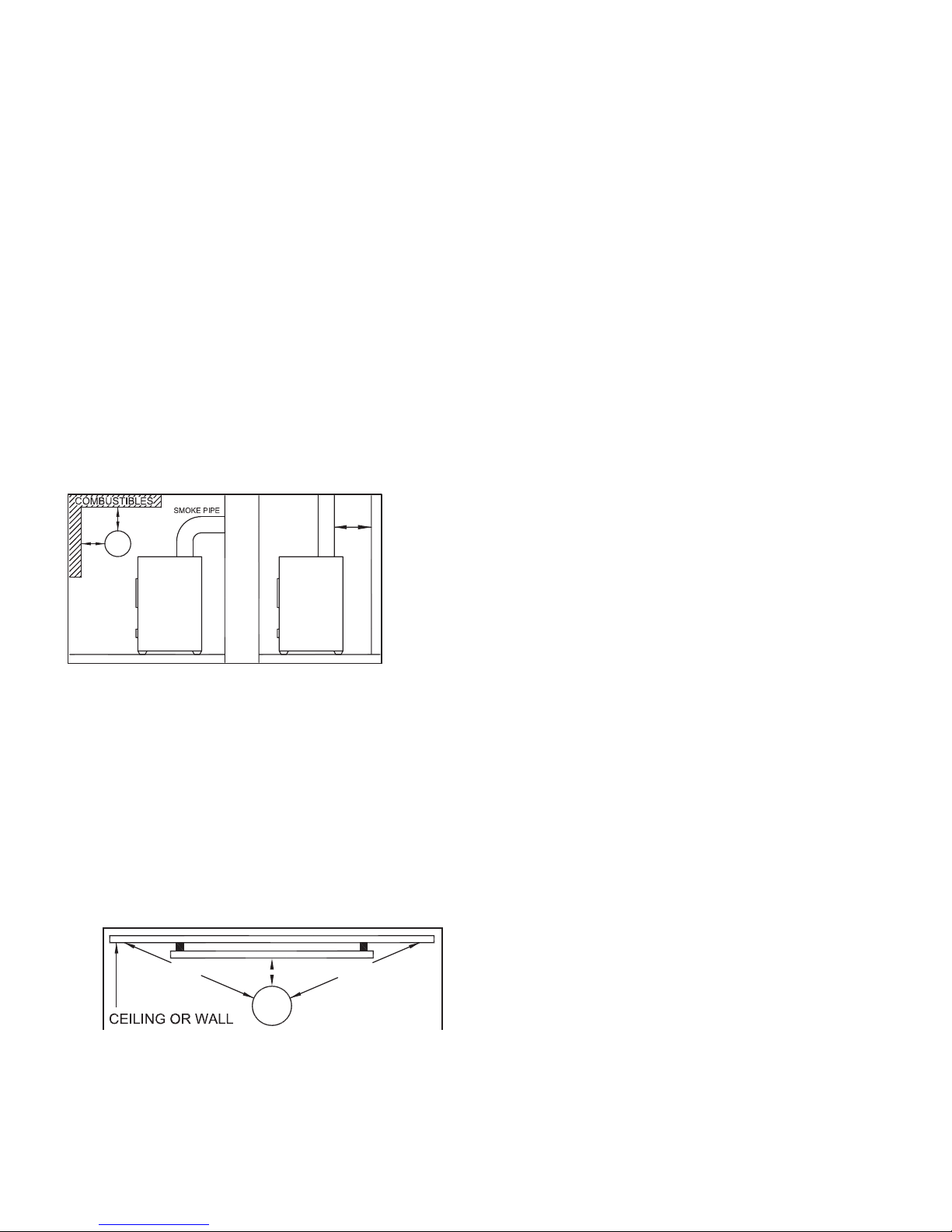
SMOKE PIPE INSTALLATION
Clearances to combustible materials (i.e. paneling, ceiling tile, sheet rock, plaster, draperies, casements or wood
trim, etc.) will vary with the type of fl ue connection used.
Be sure to maintain the specifi ed clearances for your type
of installation.
TYPE OF FLUE REQUIRED
CONNECTION CLEARANCE
24 Gauge or Heavier ............................. 18”
Single Wall Stainless Steel or Black Pipe
Double Wall, Stainless Steel or .............. 6”
Double Wall, Black Pipe w/
Stainless Steel Inner wall
Class A 103HT All-Fuel or Equivalent 2”
According to NFPA standards, single wall stove pipes
can be within 9” of combustibles provided an approved
fi re retardant material covered with 28 gauge sheet metal,
spaced out 1” on non-combustible spacers, is utilized. See
illustration.
so that it maintains clearances, keeps condensation and
creosote within the pipe, and is capable of withstanding a
2100°F degree chimney fi re.
1. The connector pipe should slant down toward the furnace a minimum of 1/4” to the foot. At no time should
the pipe turn downward toward the chimney or run
horizontal.
2. There should be no more than two 90 degree elbows.
3. The connector pipe should never be longer than six
feet. If it is absolutely necessary to make a run of more
than six feet (not recommended) use extra support
brackets every 3 feet.
4. The connector pipe should never be reduced to a
smaller size than fl ue opening on the furnace.
5. The connector pipe should not block the fl ue of the
chimney or extend into it in any way.
6. A good airtight thimble should be used to hold the connector pipe in the chimney. It should be constructed so
the connector pipe can be removed for cleaning.
7. The connector pipe should not leave the heated portion of the building to reach the chimney.
When using a Class A or double wall fl ue pipe connection,
follow the manufacturer’s instructions.
When constructing a single wall smoke pipe, the following
guidelines must be observed.
1. The connector pipe should be 24 gauge or heavier
stainless steel or black pipe.
2. Secure all joints with three #8 screws.
3. If the connector pipe must pass through a wall, an approved insulated or ventilated thimble, at least three
times the diameter of the smoke pipe must be used.
(i.e. a 6” diameter smoke pipe needs an 18” thimble).
18” [46cm] 18” [46cm]
9” [23cm]
8. The connector pipe should not pass from one story
to the next before entering the chimney, nor should it
pass through any closed or enclosed space.
9. The connector pipe and any elbows must be of 24
gauge or greater.
10. The connector pipe should not be located near or in a
walk way or well traveled area.
11. All male ends of connector pipe should run or point
towards the furnace.
12. Install a cast iron adjustable damper in the fi rst joint of
the connector pipe, nearest to the fl ue collar.
DAMPERS ON STOVE PIPES
When burning coal, we recommend a Barometric Draft
Damper be installed at a safe convenient place between
chimney and your furnace preferably less than 3’ from the
fl ue collar.
When you have installed the connector pipe between your
furnace and the chimney, tap the pipe hard with your fi n-
gernail. Remember the sound it makes - it will be a “ting”
echoing inside the stove pipe. If later you tap and hear
a muffl ed thud, you are building up soot in the pipe and
should clean it. This pipe should be cleaned at least once
or twice during the heating season.
4. The connector pipe should never be used as a chimney.
IMPORTANT INFORMATION FOR ALL
CONNECTOR PIPES
The connector pipe must be constructed and installed
4
DO NOT CONNECT TWO HEATERS TO THE SAME
CHIMNEY FLUE. The National Fire Prevention Association recommends that wood burning appliances vent into
a separate fl ue from gas or oil furnaces. If such an instal-
lation is contemplated, fi rst check with a local building in-
spector to fi nd out if a separate fl ue for a wood burner is
required.
Use of a Barometric Draft Control (when burning wood) is
recommended ONLY in the event your chimney creates
excessive draft leading to an over-fi ring condition.
HEATED AIR DISCHARGE
The Clayton furnace is designed for use as a supplemental heating source. When used as a supplementary furnace, it is connected in conjunction with an oil, gas, or
electric furnace to the existing duct work which distributes
the heated air into several rooms and/or areas.
Though United States Stove Company expressly Does Not
recommend the use of its furnaces to be installed and/or
used as a free-standing heater, it is possible to achieve a
reasonably safe and functional installation IF certain standard procedures are followed. The following are guidelines only and are intended to enable the furnace user to
obtain reasonable effi ciency from his furnace, and with
due respect to safety when installing as a “free-standing
heater”. If installed correctly, and in accordance with the
instructions found in this manual, your warm air furnace
may be installed as a “space heater” within living quarters,
cabins, garage, or workshop. Please adhere to the following:
1. The use of a cold air return and/or fi lter box is man-
datory. This will not only increase your blower life and
provide fi ltered air, it will also help prevent the blower or
blowers from “capturing” heated air exiting from the top of
the furnace heat outlets.
2. If installed as purchased , without directing the heat
away from the furnace itself, it will simply sit and cycle,
turning the blowers off and on. The thermostat may not
function properly.
3. All larger furnaces (or those with multi-speed blowers)
absolutely require BACK PRESSURE to prevent premature motor winding failure. If allowed to operate at high
RPM (As in “FREE AIR” mode - no duct work or fl ow re-
strictions) the windings overheat, insulation melts and the
motor simply burns up - not covered under warranty.
CONNECTING HOT AIR DUCT
TO FURNACE
We strongly recommend that the hot air duct work be installed by a home heating specialist. If doing the installation yourself, before you decide which installation will best
suit your needs, consult a qualifi ed heating technician and
follow his recommendations as to the safest and most effi cient method of installation.
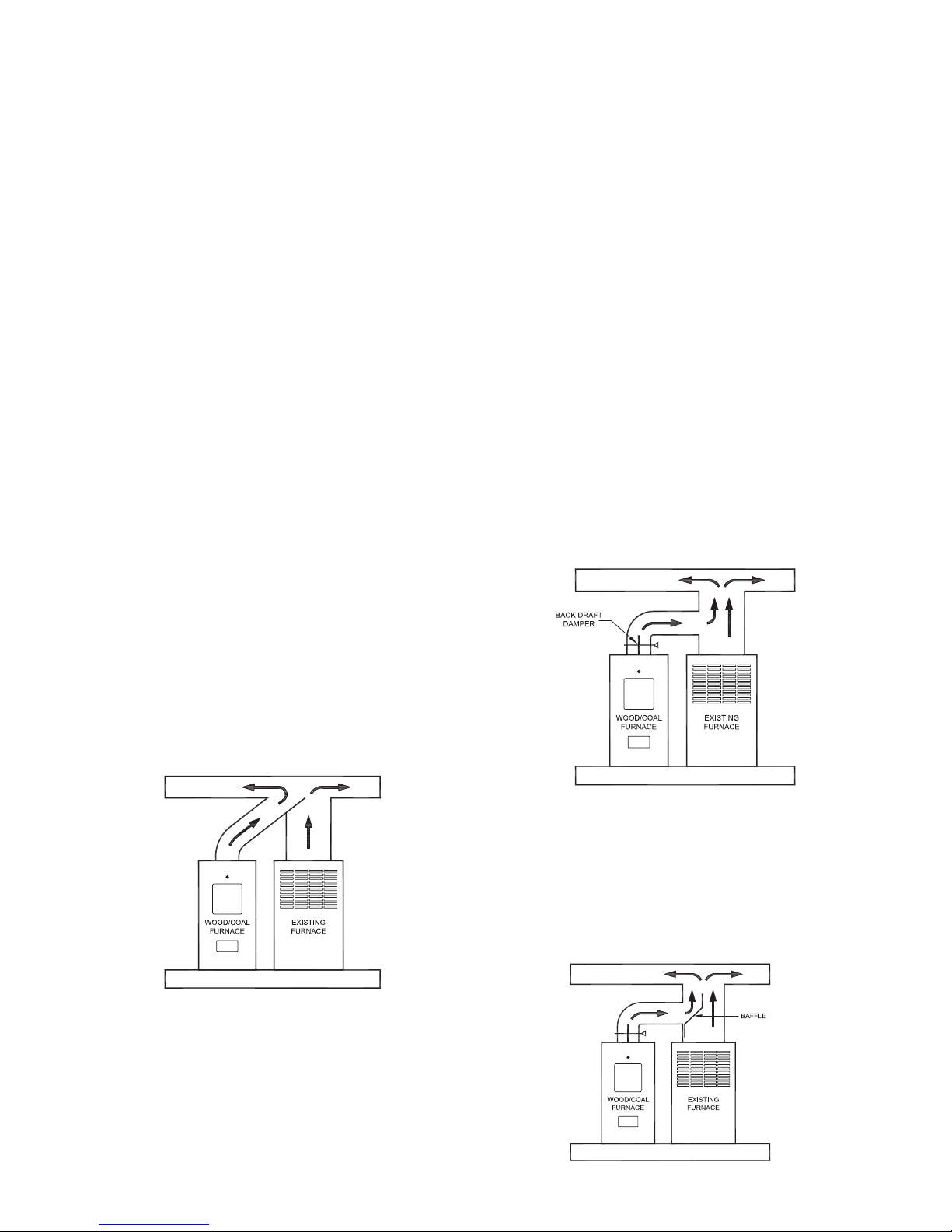
The following illustrations are the ONLY acceptable confi gurations when installed with existing oil or gas furnaces.
INSTALLATION EXAMPLES
Installation #1
With this installation, a back draft damper (optional) is inserted
into the heat run before the plenum of the existing furnace to prevent air from the existing furnace to blow back into the furnace
when it is not in use. When a back damper is employed, it should
be located as close to the existing furnace plenum as practical.
INSTALLATION #2
Extending the hot air duct from the furnace into the existing plenum
will help direct the fl ow of air from the furnace as well as the fl ow
in the existing furnace. Ducting entering the existing plenum at an
angle (approximately 45 degrees) will facilitate air fl ow from the fur-
nace while diverting air from the existing furnace.
INSTALLATION #3
The baffl e on this system should be made the full width of the furnace
plenum in order to properly direct the air into the distribution ducts.
5

NEGATIVE
PRESSURE IN
BASEMENT
THE PLENUM OPENINGS DIFFER
BETWEEN THE 1602 AND 1802
PLENUM OPENING
MODEL 1602 - 13” x 18” Rectangular
MODEL 1802 - 18” x 18” Rectangular
RETURN AIR IS VERY IMPORTANT
When installing a Clayton Furnace, return air MUST BE incorporated into the system. Return air can be provided by
installing a separate duct system or by tying into the cold
air return of an existing gas or oil furnace. The cold air return duct can be connected to the furnace with either a factory manufactured U. S. Stove fi lter box, model UFB908 or
an equivalent fabricated from sheet metal.
When installing a cold air return, the minimum size shall
be a 16” x 20” or equivalent (320 sq. in.) in order to insure
proper furnace performance. Failure to provide return air
ducts of the specifi ed size will void your warranty.
A fi lter should be installed in the cold air return. Furnace
fi lters should be checked and cleaned/replaced regularly.
If return air is not provided, the warm air distributed into
your home will be restricted and the effi ciency of the fur-
nace is decreased. Without a return air system, warm air
6
will be drawn into your basement, unnecessarily heating
unused areas of the home. In extreme cases, if your basement or utility room is fairly airtight, the blowers on the
furnace could depressurize the room and pull toxic fl ue
gases from the furnace, a gas water heater, or gas furnace. The fumes could then be distributed throughout the
house.
COMBUSTION AIR
All fi res need air (specifi cally oxygen) to burn. Furnaces,
fi replaces, and wood burning furnaces need enough oxy-
gen for complete combustion of their fuels. The incomplete
combustion that takes place when a furnace is “air starved”
causes carbon monoxide (CO) to be formed in quantities
that can be dangerous inside a well sealed house. Having a source of combustion air from outside the home will
prevent “air starvation” of the furnace. A simple positive air
supply can be constructed using dryer vent and a modifi ed
termination.
FURNACE ASSEMBLY INSTRUCTIONS
Unpack your Furnace and insure that there is no shipping damage. If damage exist, please contact your dealer immediately. Your Clayton Furnace will require some
assembly before operation. All needed hardware and
components for the following assemblies are included
within the parts boxes inside the furnace and in the ash
pan. Read and follow these instructions for proper furnace assembly.
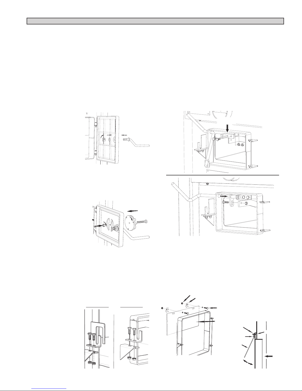
DOOR HANDLES
Insert door handle into door. From rear side of door, place
a 1/2” washer over the threaded part of the handle, then
attach the lock nut. Tighten the nut, then back off 1/4 turn
to allow free operation of the handle. Follow these same
directions for the ash door handle assembly.
(2) Door Handle
(2) 1/2” Washer
(2) 1/2” Lock Nut
SHAKER GRATE HANDLE
Insert the Shaker Rod into the hole on the ash door frame
as shown. Then attach the Shaker Bracket to the front of
the furnace using two 1/4-20 x 3/4” Hex Bolts and two
1/4-20 Lock Nuts. Next, insert the shaker Rod into the
bracket and attach to the shaker grate bar using the 1/420 x 1” Hex Bolt and a 1/4-20 Lock Nut. The bolt and nut
retaining the shaker bar and rod should be left loose to
allow free movement of the grates.
(1) Shaker Rod
(1) Shaker Bracket
(1) 1/4-20 x 1” Hex Bolt
(2) 1/4-20 x 3/4” Hex Bolt
(3) 1/4-20 Lock Nut
BRACKET
ASH DOOR SPIN DRAFT
Screw the spin draft onto the 3/8” x 2-1/2” carriage bolt.
Then screw the spin draft and bolt into the ash door allowing approximately 1/2” of the bolt to stick through the
back side of the ash door. Secure the bolt in place with
the 3/8”-16 lock nut.
(1) Spin Draft
(1) 3/8-16 Carriage
Bolt
(1) 3/8-16 Lock Nut
FUEL & ASH DOOR LATCH
With two 1/4-20 x 3/4 hex bolts each, attach the door
latches to the door latch mounting brackets on the left
side of the door frames as illustrated. The slots in the
brackets and latches are for door seal adjustment. Make
the proper adjustments, then tighten the nuts. The door’s
gasket should be snug against the door frame on the furnace.
(1) Feed Door Latch
(1) Ash Door Latch
(4) 1/4-20 x 3/4 Hex Bolt
(4) 1/4-20 Kep Nut
Feed Door
Illustration
Ash Door
Illustration
SMOKE CURTAIN
Using two 1/4-20 x 1-1/4” Carriage bolts, the smoke curtain clips and two nuts, attach the smoke curtain in place
above the Fuel Feed Door as shown below. After installation, the smoke curtain should swing freely back into
the furnace.
(1) Smoke Curtain (2) Smoke Curtain Clips
(2) 1/4-20 x 1-1/4 Carriage Bolt (2) 1/4-20 Kep Nut
1/4-20 NUT
SMOKE CURTAIN
CLIP
1/4-20 x 1-1/4
CARRIAGE BOLT
SMOKE CURTAIN
SMOKE CURTAIN
CLIP
SMOKE CURTAIN
NUT
BOLT
FRONT
7
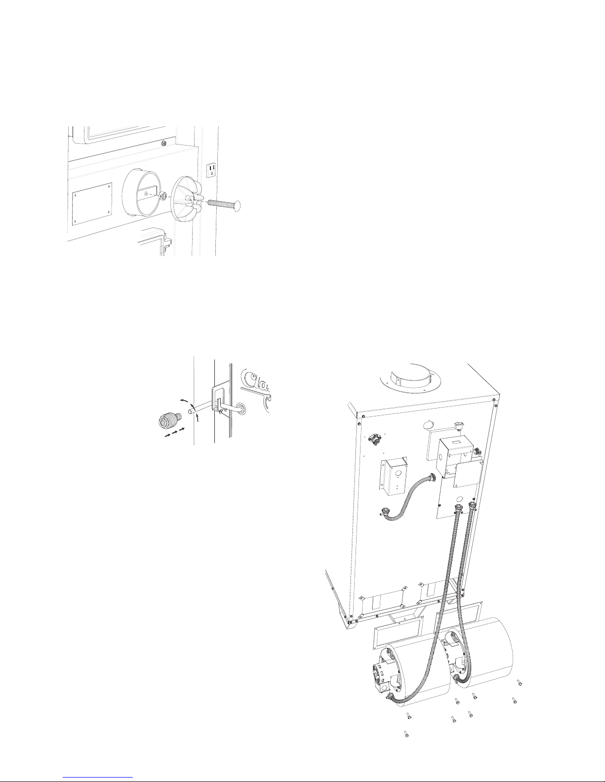
SPIN DAMPER
Screw the spin draft onto the 3/8” x 2-1/2” carriage bolt
followed by the 3/8”-16 lock nut. Then screw the spin draft
and bolt into the Combustion Air Inlet allowing approximately 1/2” of the bolt to stick through into the threaded
part of the tube. Secure the bolt in place with the 3/8”-16
lock nut by tightening it against the tube bracket.
(1) Spin Draft
(1) 3/8-16 Carriage Bolt
(1) 3/8-16 Lock Nut
SPRING HANDLES
Attach the four(4) spring handles to the Feed/Ash Doors,
Baffl e Rod, and Shaker Rod by twisting the springs
counter-clockwise while applying pressure until you have
screwed them approximately 3/4”-1” onto the rods.
conduit assembly from the snap-disc box to the junction box as shown.
7. If not already installed, snap the rocker switch into
the top of the junction box.
8. Attach the two longer conduit assemblies to the junction box and to each blower.
9. Provide a 110v power supply and secure it with the
cable clamp to the right side of the box. Make all
wire connections per the wiring schematic in these
instructions using the supplied hardware. Mount the
junction box cover.
(2) 800 CFM Blower
(2) Gasket, Blower
(8) Tinnerman Clip, 1/4-20
(8) 1/4-20 x 3/4 Bolt
(2) Conduit Assembly (5ft)
(1) Honeywell Limit Control
(1) Conduit Assembly (1ft)
(1) Junction Box
(1) Insulation (5” x 5”)
(1) Rocker Switch
(1) Romex Cable Clamp
(1) Fan Center Control
(3) 73B Wire Nut
(1) 74B Wire Nut
(1) Female Term. (blue)
(1) Female Term. (red)
(8) #10 x 1/2 Screw
(4) Spring Handles
DISTRIBUTION BLOWER & ACC.
1. Remove all contents and insure that all components
are present for assembly. See the part list below
2. Begin by attaching the blowers to the unit. Insert a
clip into each mounting hole in the furnace’s cabinet
back. Be sure to install the gasket between the blower and cabinet back. Insert the eight bolts provided
and tighten.
3. Insert the adjustable snap-disc into the hole in the
upper-left hand corner of the cabinet back. Attach using two of the #10 x 1/2 screws provided.
4. Find the Snap-Disc box, the small black box shown
on the left side in the illustration. Attach the shorter
conduit assembly to the bottom of the box, securing
it with the nut on the fi tting.
5. Plug the wires onto the snap-disc (see wiring schematic) and then attach the box to the back of the unit
using four of the #10 x 1/2 screws provided.
6. Next, mount the junction box and insulation using
two of the #10 x 1/2 screws provided. Install the 5 x
5 insulation between the cabinet back and junction
box, with the foil side to the cabinet back. Attach the
8
 Loading...