

United Security Products Exit Alert XP-6-EA, Exit Alert EA-XP-4, Exit Alert XP-4-EA, Exit Alert EA-XP-6, Exit Alert XP-5-EA Quick Start Manual
...
INSTRUCTIONS – QUICK START GUIDE
Exit Alert 900MHz Wireless Sensor Mats and 900MHz
Wireless Receivers, together, form a convenient and
reliable system for controlling dementia related
wandering.
MATS AND RECEIVERS
If you purchased EA-XP-6, EA-XP-4, or EA-XP-5, a
WR-900-1 Receiver is included in those Systems.
If you purchased an XP-6-EA, XP-4-EA, or XP-5-EA
Mat, you may have purchased either the WR-900-1 or
the optional HUB-WR900-40 Receiver separately.
When Transmitter Mats and Receivers are ordered as a
set, they are coded (programmed) to communicate with
each other.
WR-900-1 will monitor up to 10 Mats, HUB-WR900R-40
can monitor up 40 Mats. WR-900-1 recognizes multiple
Mats (locations) as a single zone. HUB-WR900R-40
recognizes multiple Mats individually and identifies their
locations in a “data log” displayed on an LCD screen.
INSTALLATION – SET UP
Select a convenient location for the Receiver; five feet
above the floor is recommended.
Follow the Receiver instructions, to arrive at the point
where it is powered-up and in operating mode. The
Receiver is now seeking the Transmitter Mat that it was
programmed to electronically monitor.
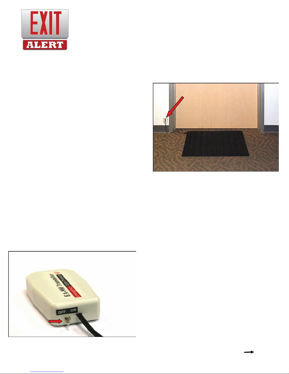
With the Transmitter Mat lying flat and in proximity of the
Receiver, move the Toggle Switch (located on the
attached transmitter module) from OFF to ON position.
See Fig. A.
Toggle Switch
Wait 20 seconds, and while watching the Receiver,
apply pressure (using your palm) to the center…
Fig. A
XP-6-EA EA-XP-6
XP-4-EA EA-XP-4
XP-5-EA EA-XP-5
area of the Mat. The Receiver will respond according
to the features of the particular model you are using.
A Red flashing strobe light during alarm state is
common to each of the two possible Receiver types.
Now that transmitter/receiver communication has been
verified (test procedure) you are ready to install the
Mat at the exit area you wish to monitor.
Place the Mat either inside or outside an exit door or
window. Route the wires, and attach the Transmitter
Module to the wall in any convenient location using the
supplied Velcro Mounting Squares. See Fig. B
Transmitter Module
If necessary, the Mat can be secured to a floor surface
with silicon seal or duct tape to prevent movement
caused by foot traffic.
A thin floor mat or a throw rug will obscure the
Transmitter Mat and cover the wires leading to the
Transmitter Module.
After Receiver and Transmitter Mat installation is
completed, test the system by having an assistant
step on the Mat while you confirm alarm state at the
Receiver.
MONITORING
When the Transmitter Module is in OFF position, it will
not signal the Receiver. When the Transmitter Module
is in ON position, and when the Mat is stepped on, it
will signal the Receiver which in turn alerts the
caregiver of a patient’s attempt to exit and wander.
Caregivers can enter and exit without tripping the
alarm when the Transmitter Module is in the OFF
position. Caregivers can exit in OFF position, and
then reach back and turn ON the Transmitter Mat to
start patient monitoring.
ADVANCED MONITORING
Exit Alert Systems have the unique feature of being
portable and expandable. It can go with the patient
and caregiver when traveling or on extended family
visits, and monitoring capabilities can be…
Fig. B
expanded upon if Alzheimer’s conditions change or
advance.
The functional features of the two Exit Alert Receivers,
along with the addition of more than one Transmitter
Mat, are the key elements involved in expanding the
monitoring capabilities of Exit Alert Systems.
Both WR-900-1 and HUB-WR900R-40 feature flashing
strobes and audible (high/low) alarms. Both Receivers
also feature Alarm outputs that can be connected to a
nurse call station and/or an Auto Voice Dialer.
Auto Voice Dialers, available through Emergency Caller
Products / USP Healthcare, dial designated cell or
landline phone numbers and deliver a recorded
message when triggered by either WR-900-1 or HUBWR900-R-40.
Please consult with one of our Healthcare Monitoring
Specialist for assistance in expanding your System’s
monitoring capabilities.
BATTERY REPLACEMENT
The Transmitter Module is powered by one CR2450 3V
Lithium Coin Cell Battery. In OFF position this Battery
can last up to ten years.
Both Exit Alert Receivers will alert (strobe flash, audio
tone, nurse call, and/or Auto Voice Dialer) when
Transmitter Battery condition is low. Depending on the
frequency and duration of monitoring sessions, this
Battery may need to be replaced from time-to-time.
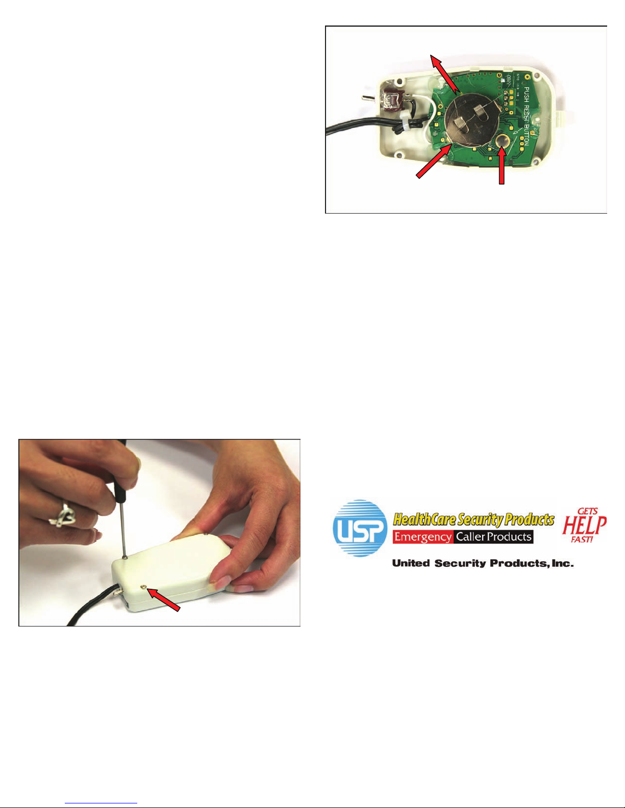
Replace the Battery by removing the four small phillips
screws on the backside of the plastic housing. See Fig.
C.
.
Fig. C
Screws x 4
Separate the two-part housing, slide the old Battery out,
and slide a fresh Battery in + up. See Fig. D.
After replacing the Battery, press the reset button
(located next to the Battery) to reset the Transmitter
Module to its most recent programming. See Fig. D.
Reassemble the two-part housing making sure that the
rubber gasket is in place.
Slide Out
Battery
Reset Button
Fig. D
TESTING
Even though Exit Alert monitors battery condition, the
system must be checked before each monitoring
session. Refer to “INSTALLATION – SET UP” for the
quick and simple test procedure.
RANGE
Range is the operational distance between the
Transmitter Mat (or Mats) and the Receiver.
Exit Alert incorporates the most advanced 900MHz
technology available, making it suitable for both
homecare and facility monitoring.
Open field, or line-of sight Range, can be almost a mile.
Building structure, obstructions between transmitter and
receiver, and environment, can reduce Range.
In most homecare and healthcare facility in-building
environments, Exit Alert Range will be 100 feet or better.
Thank you for choosing…
40 Years of Superior American Manufacturing
Made in U.S.A
Email: sales@unitedsecurity.com
Web: www.unitedsecurity.com
(T) 800-227-1592
(F) 858-413-0124
www.emergencycaller.com
U.S. and FOREIGN PATENTS PENDING
REV. 4.09
 Loading...