

Page 1
MODEL AD
-
2000
w i t h V e r i f i c a t i o n
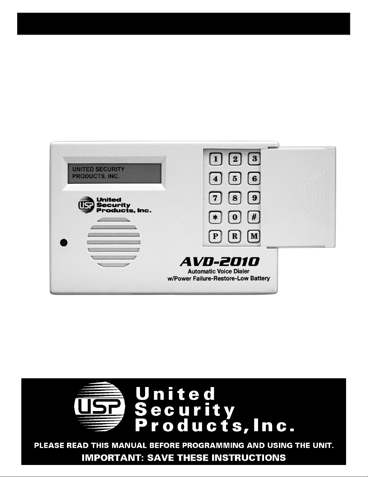
MODEL AVD-2010
Automatic Voice/Pager
Automatic Voice Dialer
w/AC Power Off, AC Power Restored, Low Battery Notification
Dialer System
Not just the next generation…it’s the next millennium !
Versatile * Full-featured * Easy to Program
2-way Listen in Verification
Operates with all alarm systems
Ideal stand-alone dialer
Provides reliable emergency notification 24 hours a day
Page 2

MODEL AD
-
2000
For Technical Service and Support: Call (858) 413
-
0149 * Fax (858) 413
-
0124
MODEL AVD-2010
Owner’s Manual and Operating Instructions
The Automatic Voice/Pager Dialer System
For The Next Millennium
Congratulations!
Thank you for purchasing United Security Products, Inc.’s Model AVD-2010 - the “smartest”, most comprehensive automatic voice/pager security dialer available. Representing an exciting new level of achievement, the
AVD-2010 combines technologically advanced features, ease of programming and reliable operation in a compact, unobtrusive dialer completely compatible with any security alarm system. Installation and hookup are
quick and easy, whether installed in conjunction with normally open, normally closed dry contact or voltage
activation sensors. The unit can also function as a stand-alone device, by simple connection to an ordinary telephone jack. The keypad cover glides on and off for added attractiveness and security.
The AVD-2010 features a “smart’ Power Monitoring System (PMS) that constantly operates in the background without interfering with any of the dialer functions under normal power conditions. In the event of a blackout, or when
battery voltage falls below a safe level, or when power is
restored, the PMS automatically dials out and notifies by
means of pre-recorded voice messages which of the three
conditions have been detected: “AC POWER OFF”,
“BATTERY LOW”, or “AC POWER RESTORED”.
The AVD-2010 is extensively programmable, offering personalized customization to fulfill virtually any residential or
business requirement. Plain-English prompts walk the user
through the process in a timely manner.
Programming options abound, allowing the user to:
• Store up to 8 telephone/pager numbers.
• Choose 1- 9 calling efforts for the numbers dialed.
• Select 1-3 message repeats.
• Record a variable combination (maximum: 7) of in-
structional outgoing messages (total elapsed time: 60
seconds).
How It Works
Program up to 4 separate input channels with individually
enable/disable, entry/exit delay and activation options (Normally Open (N.O.), Normally Closed (N.C.)
(dry contact or voltage activation) including momentary and
continuous activation for each).
Further individualize each channel by selecting the delay
times, telephone/pager numbers to be dialed and the specific
outgoing messages to be played.
Please Familiarize Yourself With These Instructions Before
Installation/Operation. This guide describes how to program
and operate the dialer. We strongly recommend that you read
the entire manual before attempting to use the unit.
To enhance ease of programming and operation, this guide
includes:
• A Programming Sample/Quick Setup review on page 13
with a corresponding Program Planner.
• A Blank Program Planner on page 14. One copy of this
Planner should be kept in a safe place by the end user.
A separate copy should also be retained by the installer.
We are happy to provide a full measure of security reassurance and peace of mind with the Model AVD-2010. For information about other innovative United Security Products
equipment, call (800) 227-1592.
Monday – Friday * 6:30 AM – 4:00 PM PST
2
E-mail: [email protected]
Page 3

TABLE OF CONTENTS
THIS PACKAGE CONTAINS:
1 ea. MODEL AVD-2010
1 ea. AC-2P ADAPTER
Section Page number
Package contents…………………………………………………………………
Panel Displays……………………………………………………………………
Installation Hookups: Alarm Panel……………………………………………...
Installation Hookups: Stand Alone………………………………………………
Programming the Dialer………………………………………………………….
Overview………………………………………………………………………
Programming Phone/Pager Numbers………………………………………….
Programming Auxiliary Information………………………………………….
Programming/Recording OGMs………………………………………………
Programming Channels………………………………………………………..
Testing Your System……………………………………………………………..
Operating Your System…………………………………………………………..
Additional Features………………………………………………………………
Power Fail/Restore Notification…………………………………………………
Sample Program Planner…………………………………………………………
Blank Program Planner………………………………………………………
Specifications…………………………………………………………………….
Dialer Accessories………………………………………………………………..
Important Information……………………………………………………………
1 ea. PP-1 POWER PACK
1 ea. PHONE CABLE
1 ea. INSTRUCTION MANUAL
4 ea. 1K RESISTORS
3
4
5
6
7-11
7
8
9
10
10-11
11
12
12
13
14
15
16
16
17
IMPORTANT
AVD-2010 PERFORMS BEST WHEN CONNECTED TO AN ANALOG “LAND
LINE.” DIGITAL CONVERSION OF ANALOG VOICE IN TELEPHONE LINES
MAY RESULT IN A SLIGHT DELAY OF SIGNAL RECEIVED. IF AVD-2010 IS
CONNECTED TO A DIGITAL PHONE LINE, IT MAY BE NECESSARY TO
REPEAT SAYING “HELLO” IN ORDER TO RELEASE THE PRE-RECORDED
MESSAGE.
3
Page 4
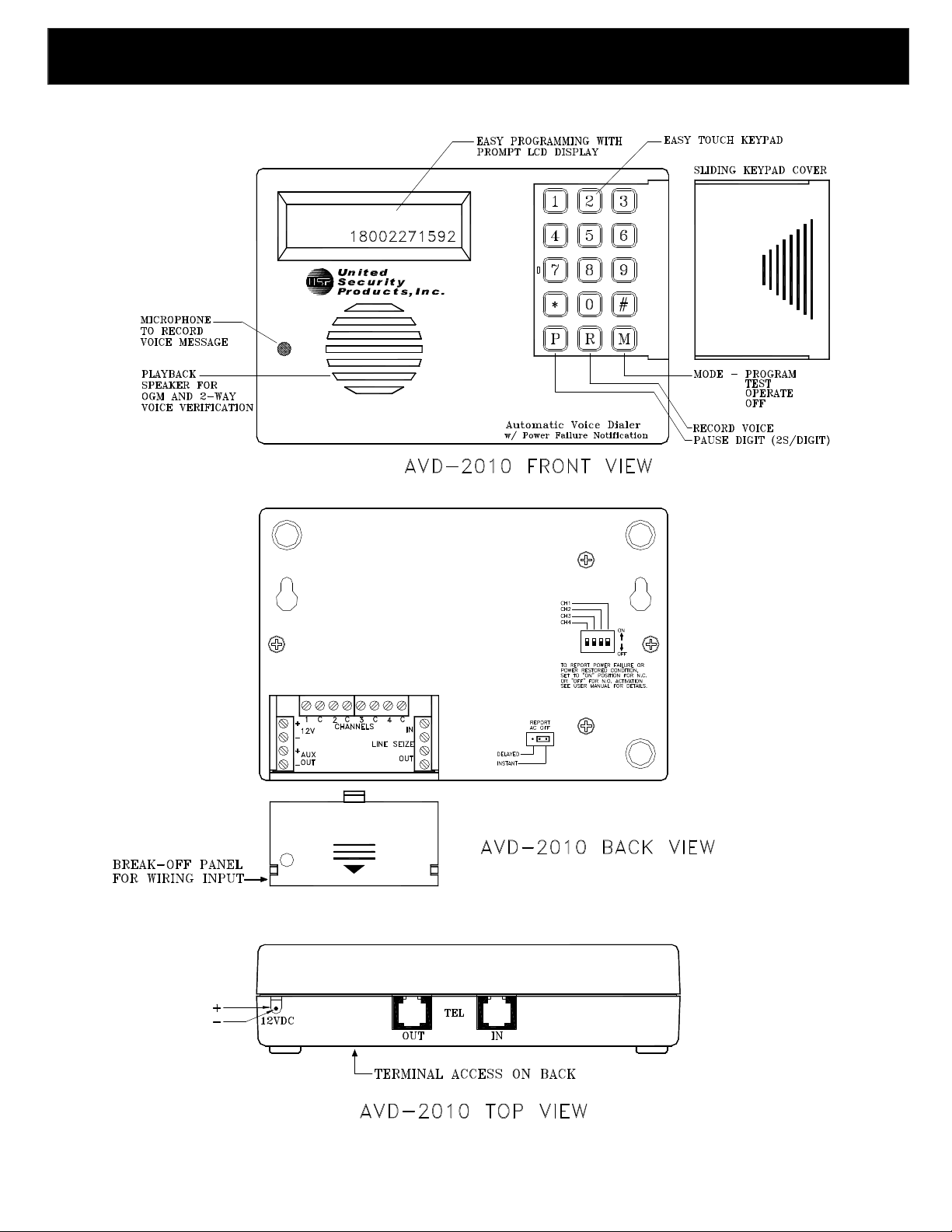
PANEL DISPLAYS
PANEL DISPLAYS
AVD-2010
4
Page 5
AVD
-
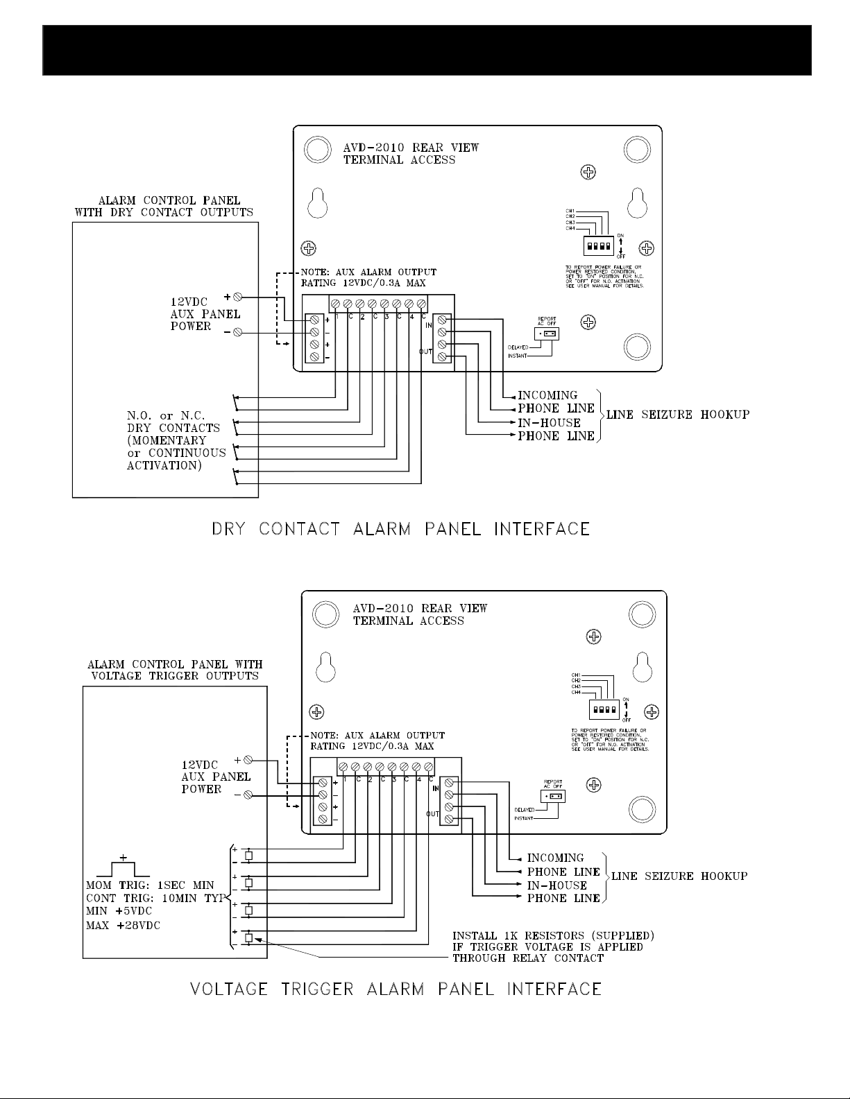
2010 INSTALLATION HOOKUPS
5
Page 6
CD
-
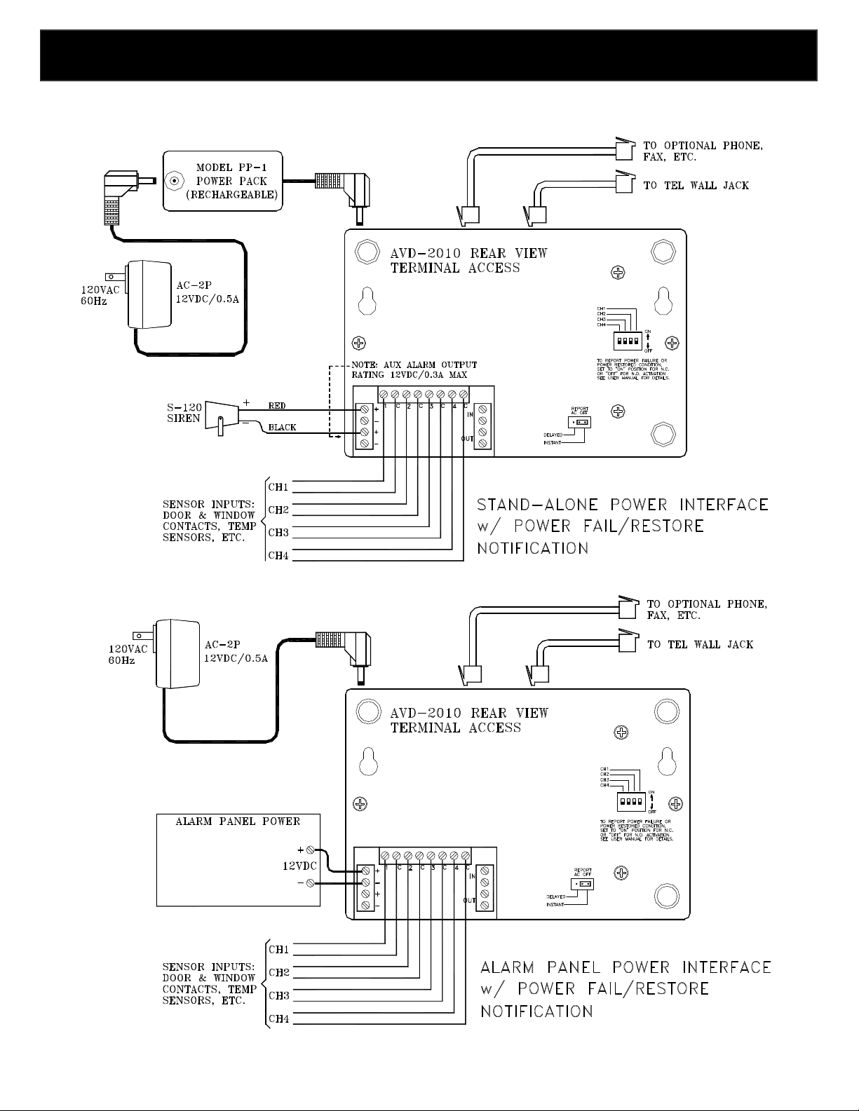
2000 INSTALLATION HOOKUPS
AVD-2010 INSTALLATION HOOKUPS
IMPORTANT: AC-2P and PP-1 MUST BE USED
when Monitoring AC Power
6
Page 7
Overview
PROGRAMMING THE DIALER
Please study this section thoroughly before beginning to program the dialer, referring to the Sample Program
Planner on page 13. Then, select from among the options for each feature, listing each choice in pencil on the
blank Program Planner on page 14. Once the dialer is correctly programmed, list each choice in ink. One copy
of the Planner should be kept by the installer; one copy should remain with the end user.
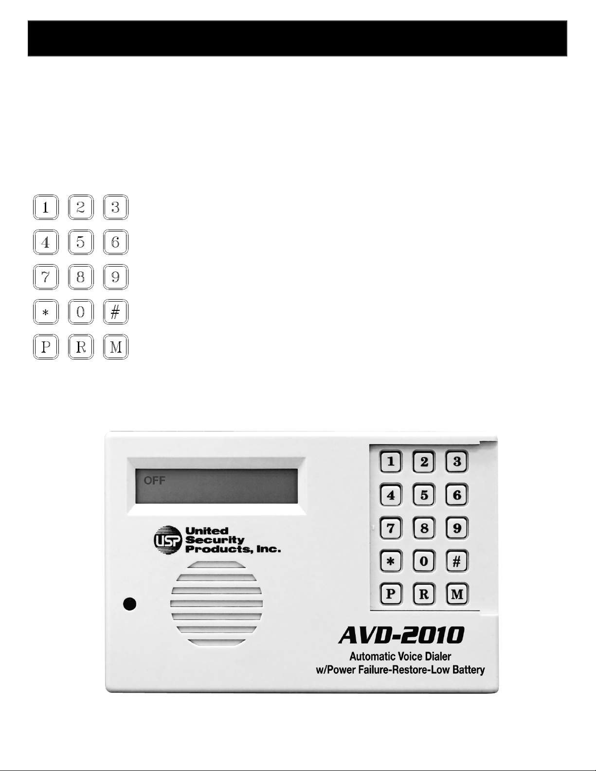
A look At The Keypad
• CALLOUT FOR NUMERALS:
Press these keys to enter telephone numbers and other programming information as
specified in this manual. A maximum of 50 digits can be input in each phone/pager
location.
• CALLOUT FOR P:
Press this key to program in a pause. Each “P” provides a 2-second pause.
• CALLOUT FOR R:
Press this key to record the combination of identification and directional outgoing
messages (OGMs). The total elapsed OGM time cannot exceed 60 seconds.
• CALLOUT FOR M:
Press this key to change the Mode of the dialer, in sequence:
PROGRAM TEST OPERATE OFF.
Once the unit has been programmed, removing power or placing the dialer in the OFF mode will not affect the
programming.
7
Page 8
First Time Installation to Initialize Dialer Follow Steps 1 & 2.
PROGRAMMING THE DIALER
Apply power to the unit.
Press 1.
You are now ready to begin programming the dialer.
Press “*” to store the
sequence.
FOR NEXT SECTION), THEN ENTER CORRECT INFORMAT
ION.
STEP 1
The LCD will read:
NOT PROGRAMMED
PRESS KEYPAD #1
Programming Telephone And/Or Pager Numbers
All programming can be input before connecting the dialer to a
telephone line. Check the unit’s LCD as you program numbers
in the dialer to ensure accuracy. Please complete all
programming instructions before attempting to operate the unit.
Before programming your dialer to call the police, fire
department or 9-1-1 directly, you must check with these
agencies for their approval.
A maximum of 50 digits (including pauses) can be programmed
in at each location.
*PROGRAM: NUMBERS SELECT: 1-8
1(YES) 2(NO ) 0(DONE)
*This prompt will appear after a number has been programmed and this section has been exited.
STEP 1 Press location number 1-8 to program the first
number. This can be any location 1-8. You do not have to
program locations in sequence. For example, you can program
numbers in locations 3 and 5. When you are done
programming all the desired telephone and/or pager
numbers, press “O” to exit this section.
The LCD will read: PAGER
1(YES) 2(NO)
STEP 2 Press “1” if you wish to program in a numeric pager
number (step 3A). Press “2” if you wish to program in a
telephone number (step 3B), cellular phone numer (step 3B), or
a voice pager (step 3C).
STEP 3A- NUMERIC PAGERS
NOTE: WHEN PROGRAMMING NUMERIC PAGERS, YOU MUST
PROGRAM IN ONE OR MORE PAUSES. EACH “P” PROVIDES A 2SECOND PAUSE. BEFORE PROGRAMMING IN A PAGER, CALL THE
NUMBER TO DETERMINE THE NUMBER OF 2-SECOND PAUSES TO BE
PROGRAMMED IN.
If you pressed “1” to program in a numeric pager…
Press the digits of the pager to be called. The numbers will
appear on the LCD, as will the following key designations.
Press “P” one or more times in accordance with the number of
seconds needed to accommodate the pager.
(Remember, each “P” provides a 2-second pause).
Press the digits of the numeric pager code.
NOTE: SOME PAGER SERVICES REQUIRE A “#” SIGN FOR
SEPARATION OF THE NUMERIC CODE OR AT THE END OF THE
NUMERIC CODE FOR PROPER TRANSMISSION.
STEP 2
The LCD will change to read:
UNITED SECURITY PRODUCTS, INC.
then: PROGRAM: NUMBERS
then: SELECT: 1-8
0(DONE)
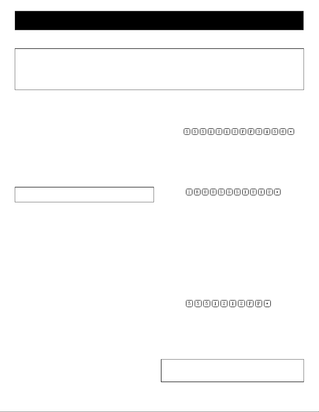
Example: To store numeric pager number 555-1212, a 4-second
Pause and code 3456:
Press:
STEP 3B – TELEPHONE NUMBERS
If you pressed “2” and wish to program in a telephone number…
Press the digits of the number to be dialed. For long-distance
numbers, first press “1” followed by the area code and then the
number. The number will appear on the LCD.
Press “*” to store the sequence.
Example: Store telephone number 1-800-555-1212:
Press:
REMEMBER/NOTE: Before programming your dialer to call the police, fire
department 0r 9-1-1 directly, you must check with these agencies for their
approval.
STEP 3C – VOICE PAGERS
If you pressed “2” and wish to program in a voice pager…
Press the digits of the pager to be called.
Press “P” one or more times in accordance with the number of
seconds needed to accommodate the pager.
(Remember each “P” provides a 2-second pause).
Press “*” to store the sequence. The number will appear on the
LCD.
Example: To store voice pager 555-1212 and a 4-second pause:
Press:
STEP 4 Repeat steps 1-3 for each number to be programmed in
each location. Select any of 8 location numbers in Step 1
(SELECT: 1-8) for each number to be programmed.
STEP 5 When you are done programming all desired
telephone and/or pager numbers, press “0” to exit this
section.
NOTE: IF YOU ENTER THE WRONG CHOICE, PRESS “M” KEY
REPEATEDLY AND RETURN TO THE “PROGRAM MODE”, THEN
SELECT THE SECTION TO CHANGE (“1” ACCEPT SECTION, “2”
8
Page 9

Programming Auxiliary Information
9) corresponding to the number of
PROGRAMMING THE DIALER
OPTION #1
No OGM. Select this option if you
do not wish to
The dialer is preset at the factory to typical telephone line (TLINE), PBX, Dialing Attempts and Message Repeat options. If
you choose to accept the following default prompts, simply
press “2” to scroll to the next section. If your phone system
requires dialing a digit to get an outside line or dial tone,
similar to PBX, then turn PBX on and enter digit to
program.
PRESETS
T-LINE…………….TONE
PBX………………….OFF
ATTEMPTS…………….2
MESSAGE……………...2
To change the presets, follow these steps.
T-LINE
The LCD will display: PROGRAM: T-LINE
1(YES) 2(NO)
Press “1” to program T-LINE.
Press “2” to scroll to the next section.
The LCD will display: PROGRAM: T-LINE
1(TONE) 2(PULSE)
Press “1” for TONE. Press “2” for PULSE.
PBX
The LCD will display: PROGRAM: PBX
1(ON) 2(OFF)
Step 1: Press “1” for ON. Press “2” for OFF.
Step 2: If “1” is entered, the LCD will display:
PROGRAM: PBX
ENTER PBX NUMBER
Enter PBX number (1 digit).
ATTEMPTS
ATTEMPTS refers to the number of times the dialer will call
each designated number. Both successful and unsuccessful
(busy or no answer) call are considered attempts.
The LCD will display: PROGRAM: ATTEMPTS
ENTER 1-9
Step 1: Press the digit (1-
times you wish the dialer to call each number.
MESSAGE
MESSAGE refers to the number of times each message will be
delivered to each designated number.
The LCD will display: PROGRAM: MESSAGE
REPEAT ENTER 1-3
Step 1: Press the digits (1-3) corresponding to the number of
times you wish the message(s) to be delivered.
After selecting the number of message repeats, the dialer will
automatically exit this section.
Structuring Your Outgoing Messages
The AVD-2010 dialer was designed with optimum versatility and
functionality in mind. Nowhere is this more apparent than in the
matrix of outgoing messages (OGMs). The user’s ability to “mix
and match” OGMs allows complete system customization and
provides ultimate efficiency.
Total OGM time is 60 seconds.
A beginning identification (ID) message of up to 15 seconds can
be programmed in (options #4, #6, and #8). Your ID message
should clearly state your name, address and other pertinent
emergency information.
Typically, each OGM will have a specific purpose. For instance,
OGM 1 can alert the person notified to contact the fire department
while OGM 2 can alert the person to contact the police
department. Typically the dialer is programmed to notify family,
friends or another responsible party. Before programming your
dialer to call the police, fire department or 9-1-1 directly, you must
check with these agencies for their approval.
OPTION #2
OPTION #3
OPTION #4
OPTION #5
OPTION #6
OPTION #7
OPTION #8
*If your ID message is less than 15 seconds in length, the remaining time will be
evenly divided among the OGMs.
Example: OPTION #4: ID plus 2 OGMs.
If the ID is 10 seconds, then each OGM can be (51 minus 10
equals 41 divided by 2 equals) 20.5 seconds in length.
record any outgoing messages.
1 OGM. Select this option if you wish to record
one OGM, which may be as long as 51 seconds.
2 OGMs. Select this option if you wish to record
two OGMs, each of which may be as long as 25.5
seconds.
ID plus 2 OGMs. Select this option if you wish to
record one ID of up to 15 seconds in length, and
two OGMs, each of which may be as long as 18
seconds.*
3 OGMs. Select this option if you wish to record
three OGMs, each of which may be as long as 17
seconds.
ID plus 3 OGMs. Select this option if you wish to
record one ID of up to 15 seconds in length, and
three OGMs, each of which may be as long as 12
seconds.*
4 OGMs. Select this option if you wish to record
four OGMs, each of which may be as long as
12.75 seconds.
ID plus 4 OGMs. Select this option if you wish to
record one ID of up 15 seconds in length, and four
OGMs, each of which may be as long as 9 seconds.*
9
Page 10
Programming And Recording Your
4).
PROGRAMMING THE DIALER
FOR NEXT SECTION), THEN ENTER CORRECT INFORMATION.
FOR NEXT SECTION), THEN ENTER CORRECT INFORMATION.
Outgoing Messages
Follow these steps to program and record your outgoing
messages. Skip this portion if you have programmed in only
numeric pagers, which rely on coded DTMF messages. As with
all AVD-2010 programming, the unit need not be connected to a
phone line when information is programmed in. Remember that
“OPT” on the LCD stands for option; “OGM” stands for
outgoing message.
NOTE: IF YOU ENTER THE WRONG CHOICE, PRESS “M” KEY
REPEATEDLY AND RETURN TO THE “PROGRAM MODE”, THEN
SELECT THE SECTION TO CHANGE (“1” ACCEPT SECTION, “2”
STEP 1 Decide which of the eight options you prefer.
STEP 2 Before programming in this option, write down all
your messages. Time them carefully, changing them if
necessary to fit the alotted time frame. Practice saying them,
clearly enunciating each message for maximum clarity in case
of an emergency. Keep a final recording script.
STEP 3 Program your option.
A) The LCD will read: PROGRAM: OGMS
1(YES) 2(NO)
B) Press “1” to program your OGMs. Press “2” to scroll to the
next section.
C) Press “1” to select the option (#1- #8) displayed or press
“2” to scroll to the desired option.
STEP 4 After selecting your option as explained above, record
your message.
A) The word RECORD will appear in the upper left corner of
the LCD, above the instruction: PRESS R. The option
selected will appear in the upper right corner. For instance,
if you selected option #2, the LCD will read:
RECORD OGM1
PRESS R
B) Speak 6-12 inches away from the microphone. Referring to
your script and speaking in a normal voice, press and hold
R (the word RECORDING will be displayed), releasing the
key after you have completed enunciating your messages.
The word DONE will appear on the LCD when the
maximum allotted time has been reached.
C) The LCD will read: PLAY OGM(S)
1(YES) 2(NO)
Press “1” to play back your recording
D) The LCD will read: ACCEPT
1(YES) 2(NO)
Press “1” to accept the recorded OGM(s). Press “2” if you
wish to re-record the messages, beginning with Step 4.
Changing The OGMs
After your system is up and operating, you may change one or
more of the recorded OGMs and/or choose a completely
different option. To do so, simply scroll to the programming
section on your display: PROGRAM: OGMS
1(YES) 2(NO)
Select the option, then begin again from Step 3 above to record
your new message(s).
10
Programming The Channels
The AVD-2010 is designed to be adaptable to a complete range of
personalized applications. Each of the four input channels can be
programmed individually for full system customization. In
addition to setting enable/disable options, entry/exit delays and
type of activation (N.O., N.C., & momentary or continuous), each
user can specify which emergency messages will be delivered and
which numbers will be dialed. The first channel activated will be
the priority channel. Numbers programmed to that channel will be
completed before the dialer moves on to the next channel(s).
Although comprehensive in scope, the system is easy to program.
Just follow these simple steps.
NOTE: IF YOU ENTER THE WRONG CHOICE, PRESS “M” KEY
REPEATEDLY AND RETURN TO THE “PROGRAM MODE”, THEN
SELECT THE SECTION TO CHANGE (“1” ACCEPT SECTION, “2”
STEP 1 The LCD will read: PROGRAM: CHANNELS
1(YES) 2(NO)
Press “1” to begin programming the channels.
STEP 2 The LCD will read: SELECT: 1-4
0(DONE)
Enter the channel you wish to program (1-
Enable/Disable
STEP 3 The LCD will read: CH X: ENABLE
1(YES) 2(NO)
(“CH X” being the channel selected)
Press “1” to enable the channel. Press “2” to disable the channel.
Exit/Entry Delays
Capable of programming up to a maximum of 3 minutes and 20
seconds each.
STEP 4 The LCD will read: CH X: EXIT DELAY
1(YES) 2(NO)
Proceed with A) if you wish to program an exit delay.
Proceed with B) if you do not.
A) To program exit delay, press “1”.
The LCD will read: ENTER 0-199 THEN
PRESS *
Enter the digits corresponding to the number of seconds you
wish to install. (For example, press “120” then press “*”, if
you wish to install a 120-second exit delay).
B) If you do not wish to program an exit delay, press “2”.
STEP 5 The LCD will read: CH X: ENTRY DELAY
1(YES) 2(NO)
Proceed with A) if you wish to program an entry delay.
Proceed with B) if you do not.
A) To program an entry delay, press “1”.
The LCD will read: ENTER 0-199 THEN
PRESS *
Press “1” to program a delay. Then enter the digits
corresponding to the number of seconds you wish to install.
(For example, press “90” then press “*”, if you wish to install
a 90-second delay).
B) If you do not wish to program an entry delay, press “2”.
Page 11

Normally Open/Normally Closed
PROGRAMMING THE DIALER
TESTING YOUR SYSTEM
FOR NEXT SECTION), THEN ENTER CORRECT INFORMATION.
STEP 6 The LCD will read:
CH X: N.O./N.C.
1(N.O.) 2(N.C.)
A) Press “1” to select a normally open channel.
B) Press “2” to select a normally closed channel.
Momentary/Continuous Activation
STEP 7 The LCD will read:
CH X: MOM/CONT
1(MOM) 2(CONT)
A) Press “1” to select a momentary trigger.
B) Press “2” to select continuous activation.
Numbers Dialed/Outgoing Messages
Following these steps allows you to choose which OGM(s) will
be delivered and which numbers will be dialed for each channel.
NOTE: Dialer LCD will only show programmed numbers and
OGM options.
STEP 8 The LCD will read:
CH X: DIAL #X
1(YES) 2(NO)
(“Dial #X” being the number in phone/pager location 1-8)
A) Press “1” to dial phone/pager #X to be dialed when the se-
lected channel is activated. Press “2” if you do not wish this
number to be dialed.
B) Continue the above procedure for each of the up to eight
phone/pager numbers programmed in.
STEP 9 The LCD will read:
CH X: OGM X
1(YES) 2(NO)
(“OGM X” being the OGM recorded in OGM options #2 - #8)
A) Press “1” to deliver OGM X when the channel is activated.
Press “2” if you do not wish this OGM to be delivered.
B) Continue the above procedure for each Channel/OGM. If you
have programmed in and recorded an ID message as one of
your OGM options, this ID will be delivered to all channels. It
will not appear in the Channel display.
NOTE: ID AND OGM(S) WILL ONLY BE DELIVERED TO TELEPHONE
NUMBERS, CELLULAR NUMBERS, AND VOICE PAGERS.
Completing The Programming
Once you have programmed in all dialing and OGM options for
each channel, the LCD will read:
ACCEPT
1(YES) 2(NO)
STEP 10 Press “1” to accept the Channel programming. Press
“2” to re-program or to revert to previously programmed setting.
You are now ready to review your programming and test the system.
PRESS “M” TO EXIT PROGRAMMING MODE.
Test your system before an emergency occurs.
Do not neglect to review programmed information and verify all
elements of your system thoroughly before relying on the dialer
to deliver the necessary information to the desired parties accurately and completely.
We strongly recommend testing the system in test mode before
connecting to a telephone line. The test mode tests the stored
information, not the full functionality of the dialer. To test the
full functionality of the dialer, the unit must be tested in the operate mode. In the test mode, the dialer will not make more than
one attempt per number dialed or play any OGM more than
once.
NOTE: IF YOU ENTER THE WRONG CHOICE, PRESS “M” KEY
REPEATEDLY AND RETURN TO THE “PROGRAM MODE”, THEN
SELECT THE SECTION TO CHANGE (“1” ACCEPT SECTION, “2”
STEP 1 Press the “M” Mode key until the LCD reads:
TEST: T-LINE
1(YES) 2(NO)
STEP 2 Press “1” to display the T-Line configuration.
The data will scroll through all selections.
Press “2” to scroll to the next section.
STEP 3 The LCD will read:
TEST: CHANNEL(S)
1(YES) 2(NO)
Press “1” to test channels.
Press “2” to scroll to the next section.
STEP 4 The LCD will read:
SELECT: 1-4
5(ALL) 0(DONE)
Select the channel you wish to test (1-4). Press “5” to test “all”
Channels. Once a channel is selected (or “all”) the programmed
channel information will be displayed on the LCD. Verify data
accuracy as the LCD scrolls through by comparing the information
displayed with that specified on your Program Planner. Listen to
your recorded message(s) to ensure that the correct OGM (if programmed) is delivered. Press “0” to exit testing.
STEP 5 Now connect your dialer to the telephone line you will
be using and test the system again, to determine if it functions
correctly in an actual emergency situation.
Make sure you notify the receiving party of your intent to call them,
and tell them it is just a test.
STEP 6 To test the operation of your entire system, set Mode to
OPERATE and proceed as explained in the next section: Operating Your System.
Test your system on a regular basis, at least once a week.
11
Page 12

You are now ready to begin operating your system, rely-
OPERATING YOUR SYSTEM
ing on the AVD-2010 to work in conjunction with your
alarm system to provide 24-hour security reassurance and
peace of mind.
When in the operating mode, the system will monitor all
the enabled channels, initiating dialing when a valid alarm
condition occurs. Upon activation the dialer will begin
calling each phone/pager number selected, in sequence,
for the pre-selected number of attempts. During each successful attempt, the voice message will be delivered 1, 2,
or 3 times, in accordance with the option selected (nu-
meric messages will only be delivered one time). In unsuccessful attempts, the dialer will move on to the next
phone/pager number after receiving 8 busy or 8 rings
without an answer. The dialer will not allow voice messages to be delivered to programmed numeric pager locations.
If you send a message to a phone attached to an answering
machine, it will consider this a successful attempt. Make
sure you designate the maximum number of message repeats to be sure that a complete message will be left on the
answering machine, because part or all of your emergency
message may be “lost” while the answering machine delivers its greeting message.
Placing your system in OPERATE can also be used as a
final test of the full functionality of each channel’s
exit/entry delay, activation, momentary/continuous trigger, phone numbers and OGM. Although serving as a test,
this mode reflects actual operation; therefore the OGM(s)
will not be heard through your dialer’s speaker but only by
each party called.
To begin operating your system, simply press the “M”
Mode key until the word OPERATE appears on the LCD.
To disarm the dialer, switch the mode to OFF by pressing
the same key. All programming information will be retained
System Notations
Here are a few explanations to help you better understand
how your AVD-2010 dialer operates. For specific information on the AVD-2010 unit alone, call United Security
Products, Inc.’s Customer Service Department during
normal business hours at (858) 413-0149.
Channel Activation
Each of the dialer’s four channels can be activated by any
of the following: a normally open dry contact, normally
closed dry contact or positive 5-28VDC voltage activation.
12
Under a momentary activation, a single violation of a chan-
nel will cause the dialer to initiate delivering all pre-selected
OGMs to all programmed numbers associated with that
channel. Under continuous activation, the dialer will initiate
the process, terminating it if/when the activated channel is
restored to a non-alarm state. Once an alarm has occurred
and all attempts satisfied, the dialer will continue to monitor
any remaining enabled channel(s). Once the activated channel has been restored to a non-alarm state, it will then be rearmed and ready for the next alarm.
Exit/Entry Delays
If a channel is activated during a pre-selected exit delay, the
alarm condition will be ignored until the delay has expired.
If an alarm occurs, the entry delay will cause the dialer to
wait before starting the dialing process. To de-activate the
dialer during the entry wait period, simply press “M” to
return to the OFF Mode. Both exit and entry delay times
can be pre-selected to range from 1-199 seconds.
Additional features
The dialer offers three innovative features that enhance the
utility of the entire system.
Listen-In
While receiving an OGM on a touch-tone phone, the called
party can press “1” to listen in to the activity at the other end
of the line for one minute. Pressing “1” again restarts the
minute increment period and can be repeated indefinitely.
When “1” is pressed the OGM will stop playing and the listen in period will start.
Two-Way
After the called party is listening-in, that party can press “2”
to begin a two-way conversation lasting for one minute.
This procedure also can be repeated indefinitely by pressing
“2” again to restart the minute. Once you are in two-way
mode you cannot go back to Listen-In.
Remote Turn-Off
The called party can remotely terminate the activated channel any time during the OGM by pressing “1” then “#” twice
within one second. The dialer will continue to monitor the
remaining channel(s). Once the terminated channel is restored to a non-alarm state, it will re-arm. If in listen-in or
two-way, simply press “#” twice in one second, for remote
turn-off.
Page 13
POWER FAIL/RESTORE NOTIFICATION
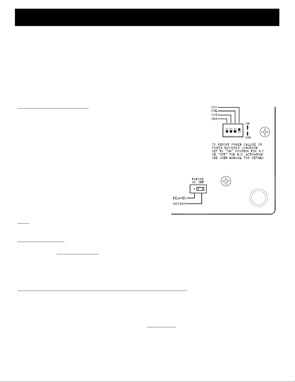
Please follow the configuration drawings on page 6 and enlarged insert below to correctly operate the Power Monitoring
System (PMS). The PMS becomes active when AC line voltage is off during a blackout or brownout lasting more that 2
seconds with the jumper on the back set to INSTANT; this feature may be very important in critical applications involving
freezers and other devices that depend on uninterrupted 120VAC line voltage. By selecting the DELAYED mode, “AC
POWER OFF” is reported after 15 minutes, only if line voltage remains absent during this period and battery power is
adequate to keep the dialer fully functional. With AC off for an extended period, perhaps as long 24 hours or longer, battery voltage may ultimately drop to 9V and below, at which time the “BATTERY LOW” message will be sent. Even
though battery has dropped below 9V, the dialer remains functional to less than 8V, hopefully long enough to alert maintainance personnel to correct the problem. As soon as AC power is back on anytime during the standby period, the “AC
POWER RESTORED” message is sent and no further action is required.
Example (see insert on right side)
In this example CH1 position is set to ON, assuming that you’ve programmed CH1 to trigger the dialer on a normally open (N.O.) condition. If, on the other hand, you’ve decided not report a power
fail/restore condition when CH1 is opened, simply set the switch to
OFF. In this example if you choose to activate the dialer on a normally open (N.O.) input, CH1 switch must be to the OFF postion to
report a power/fail condition. Likewise, if you do not want to report a
power fail/restore, then set CH1 switch to the ON position.
Rule of thumb:
a. To enable channels to trigger on a power fail/restore condi-
tion, set the corresponding switches to agree with the way the
channels are programmed.
b. To prevent channels from triggering on a power fail/restore
condition, set the corresponding switches opposite the way
the channels are programmed.
Note:
For unused channels, you may set those switches in any position. REAR VIEW DETAIL
Sequence of operation
It’s important to note that the sequence in which power fail/restore notification takes place always starts with CH1. Subsequent channels, programmed or not, will be serviced in ascending order. Because of this orderly progression, CH1 wil
always be the first to trigger the dialer on a power fail/restore condition and must therefore be the primary channel if time
of reporting is most urgent. Even though the reaction time of the dialer to an AC off condition is about 2 seconds, an unavoidable delay of up to 30 seconds can be expected before delivery of the message. On average, about 60 to 80 seconds
are required for each channel to be serviced.
What to expect when a power/fail message is initiated along with the user OGM
When the dialer is activated by a power fail/restore condition, the user-programmed OGM immediatley after the customary “HELLO” will be replaced in part by one of the power fail/restore messages. The three factory-programmed messages
“AC POWER OFF”, “BATTERY LOW”, and “AC POWER RESTORED” are preceded by a series of beep tones and are
repeated twice. The duration of each message including beep tones is 4 seconds. Therefore, the first 8 seconds of the user
OGM will be suppressed, followed by the remaining portion. Depending on the number of channels programmed, it’s recommended to split the user OGM into an ID plus OGM(s). For example: If only 2 channels (i.e. CH1 and 2) have been
designated to report a power fail/restore condition, pick the ID plus 2 OGMs option and try limiting the ID time to 8 or 10
seconds and OGMs 1 and 2 to 10 seconds each. Always test the unit by momentarily disconnecting the AC2-P adaptor
and listen to the message.
13
Page 14
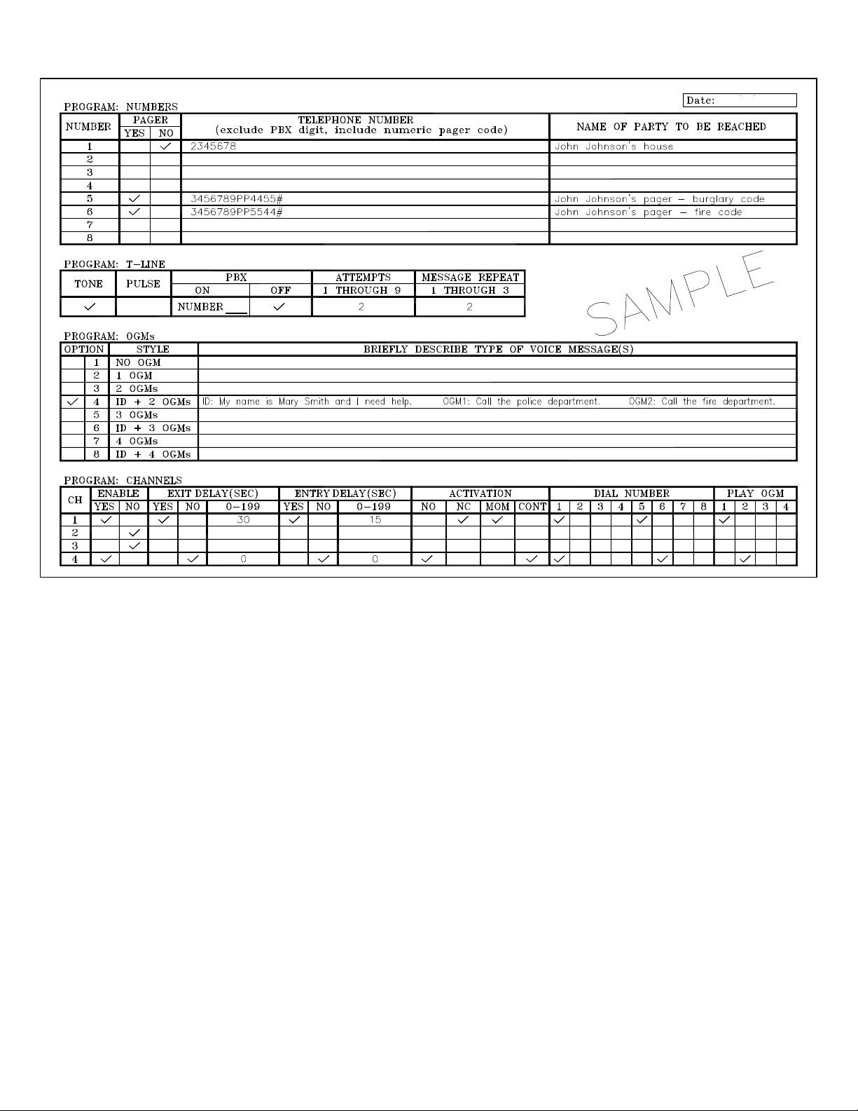
Sample Program Planner
AVD-2010 PROGRAM PLANNER
Programming Example for Quick Setup
Before programming the dialer, study the example shown on this page.
This “quick setup” example programs in one telephone number, two
numeric pager numbers, two attempts, two repeats, an ID plus two
additional OGMs, and channels 1 and 4.
Once you understand the setup, use the blank Program Planner on
page 14 to begin programming your dialer. We recommend making
several blank copies of the Planner before beginning the process. It
also is advisable to fill in the Planner in pencil initially.
STEP 1 Press “1”.
STEP 2 When the LCD reads SELECT 1-8, press “1” to install the
first phone number in location 1 press “2” to indicate no pager; then
press, in sequence, (fictitious) phone number “2345678” followed by
the “*” sign to store the programming process for that number.
STEP 3 Press “5” to install the second phone number in location 5;
press “1” to indicate numeric pager; then press’ in sequence,
“3456789PP4455#” followed by the “*” sign. The first seven digits
represent the pager number dialed; each P stands for a 2-second pause;
the next four digits followed by the # sign represent the pager code
and the * stores the programming process for that number.
Now press “6” to install the third phone number in location 6; press
“1” to indicate numeric pager; then press, in sequence,
“3456789PP5544#” followed by the “*” sign.
STEP 4 Press “0” to exit PROGRAM NUMBERS.
STEP 5 At the PROGRAM: T-LINE prompt, press “1” to choose
tone; press “2” to indicate no PBX; press “2” to program in two dialing attempts per emergency number called; press “2” to program in
two message repeats for each call.
STEP 6 Press “1” to PROGRAM OGM(S). Press “2” three times to
Scroll to option #4; press “1” to program in an ID message and two
14
specific outgoing messages (OGMs).
STEP 7 Using a prepared script and speaking six-to-eight inches
from the dialer’s microphone on the front of the unit, press “R” when
you are ready to enunciate your 15-second identification message and
your two 18-second messages. Dialer automatically prompts to next
OGM. Make OGM1 a message telling the receiving party to call the
police department. Make OGM2 a message to call the fire department.
STEP 8 Press “1” to play back all recorded messages; press “1” again
to accept. (NOTE: DIALER LCD WILL ONLY SHOW
PROGRAMMED NUMBERS AND OGM OPTIONS).
STEP 9 Press “1” to PROGRAM CHANNELS.
STEP 10 Press “1” to program Channel 1. Press “1” to ENABLE.
Press “1” then enter “30” then press “*” for a 30-second EXIT delay;
press “1” then enter “15” then press “*” for a 15-second entry delay.
Now press “2” for NORMALLY CLOSED and then “1” for
MOMENTARY activation. Press “1” to select phone/pager number 1 to
be dialed. Press “1” again to select phone/pager number 5 to be dialed.
Press “2” to not select phone/pager number 6 to be dialed. Press “1” to
select OGM1 to be delivered and press “2” to not select OGM2 to be
delivered. Press “1” to accept the channel configuration.
STEP 11 Press “4” to program Channel 4. Press “1” to ENABLE.
Press “2” twice to indicate no EXIT or ENTRY delay. Now press “1”
for NORMALLY OPEN and the “2” for CONTINUOUS activation.
Press “1” to select phone/pager number 1 to be dialed. Press “2” to not
select phone/pager 5 to be dialed. Press “1” to select phone/pager number 6 to be dialed. Press “2” to not select OGM1 to be delivered and
press “1” to select OGM2 to be delivered. Press “1” to accept the channel configuration.
STEP 12 Press “0” to exit PROGRAM: CHANNELS.
Press “M” to exit programming mode.
Page 15
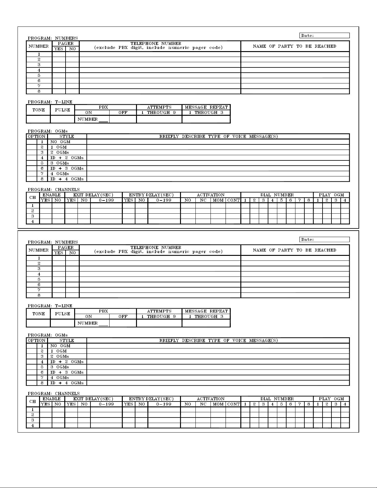
Fill out this Program Planner in pencil initially
After thoroughly testing your system, redo your Program Planner in ink.
AVD
-
2010 PROGRAM PLANNER
AVD
-
2010 PROGRAM PLANNER
One copy should be kept in a safe place by the end user; one copy should be retained by the installer.
15
Page 16

Dimensions
SPECIFICATIONS
DIALER ACCESSORIES
Power source:
Current (OPERATE mode – standby):
Current (OPERATE mode – dialing):
Activation:
Max. digits for outgoing numbers:
Operating temperature range:
Dimensions (inches):
Weight (ounces):
Mounting:
Case Material:
Color:
Warranty:
Note: Design and specifications subject to change without notice.
Power Source
AC-2P: AC/DC Adaptor
Plugs into regular 110VAC outlet to provide the dialer with the
required primary power.
AC-2: AC/DC Adaptor
12VDC/0.5A for stand alone with siren use.
PP-1: Power (Rechargeable)
Provides 24 (est.) hours of backup standby power.
PB12P:
Includes AC-2P that plugs into regular 110VAC outlet to provide power to PB12P backup battery for primary power and 24
(est.) hours of standby power
IR-1: Isolation Relay
Converts alarm output voltage to N.C. to provide clean input
trigger to dialer.
Industrial/Residential Sensors
F20: Temperature Supervisory Switch <40 F
HTS: High Temperature Switch
WLS: Water Level Sensor
RTS: Adjustable Temperature Controller, N.O., N.C.
PLS: Power Loss Sensor (110VAC)
Sensors
Magnetic Contacts – Door and Window
Glass Break Detectors
Hold Up Buttons/Emergency Switches
Pressure Mats – Sealed and Under Carpet
Motion Detectors
Siren
S-120: 2” Mini Siren, 12VDC @ 120 mA typical
9-18VDC
28mA typical.
100mA max.
1) N.C. Activation: dialer activates when an “open” is detected
2) N.O. Activation: dialer activates when a “close” is detected
3) Voltage Activation: N.C. (applied voltage: Min. +5VDC, Max. +28VDC)
N.O. (loss of continuous voltage: Min. 0VDC, Max. 0.25VDC)
50
-18 to 55 C (0 to 130 F)
6 x 4 x 1.5 in
10 oz
12.25oz
Wall or Flat Surface
ABS
White
1 Year
NOTE: CALL UNITED SECURITY PRODUCTS FOR
ADDITIONAL INFORMATION AND DEVICES NOT LISTED
HERE.
16
Page 17

IMPORTANT INFORMATION
40 Years of Superior American Manufactu
r
ing
(T) 800
-
227-1592
Care And Precautions
LOCATION
Place the dialer on a flat level surface or mount the unit on the
wall, away from extreme cold or heat, direct sunlight, excessive
humidity and away from equipment that generate strong magnetic fields. Avoid placing near large metal objects and areas
that produce smoke, dust and mechanical vibrations.
CARE
Clean the housing with a soft cloth lightly moistened with water or mild detergent solution. Never use solvents such as alcohol or thinner. Do not allow liquids to spill into the unit.
OPTIONAL BACKUP
To ensure continuous operation during power outages, hookup
to a 12VDC backup battery pack is recommended. Outer contact is (+) PP-1 available from United Security Products.
CAUTION
Do not use the dialer if a gas leak is suspected or during lightning.
PROBLEMS
If liquid or a foreign object penetrates the unit, disconnect it
immediately and contact your installer or other qualified technician.
Before calling USP, please make sure…
• You have read this manual and understand how to operate
the dialer.
• Your phone line is working.
• You check out the entire system, including external
hookup wiring and sensors attached.
• You have read the FAQ Sheet
If you still have questions or concerns, call our USP Technical
Service Department between the hours of 6:30 AM and 4:00
PM, PST, Monday through Friday.
Federal Communications Commission Radio And Television Interference Statement For A Class ‘B’ Device
This equipment generates and uses radio frequency energy and
if not installed and used properly, that is, in strict accordance
United Security Products
Issue date: 04/10/10
with the manufacturer’s instructions, may cause interference to
radio and television reception. It has been type tested and found
to comply with the limits for a Class ‘B’ computing device in
accordance with the specifications in Subpart B of FCC Rules
and Regulations (as outlined in the Code of Federal Regulation,
Title 47), which are designed to provide reasonable protection
against such interference in a residential installation.
User Instructions
If this equipment does cause interference to radio or television
reception, which can be determined by turning the equipment off,
then on, the user is encouraged to try to correct the interference
by one or more of the following measures:
• Reorient or relocate radio or television.
• Increase the separation between the equipment and receiver.
• Connect the equipment into a different outlet so that the
equipment and receiver are on different branch circuits.
• Consult the dealer or an experienced radio/TV technician for
help.
Changes or modifications not expressly approved by United security Products, Inc. could void the user’s authority to operate the
equipment.
Thank you for choosing…
(F) 858-413-0124
Email: [email protected]
Web: www.unitedsecurity.com
Made in U.S.A.
U.S. and FOREIGN PATENTS PENDING
17
 Loading...