

Page 1

united.screens GmbH - future display technology
T-OLED CRYSTALSCREEN
USER MANUAL
© 2017 united.screens GmbH
Page 2

03 Introduction
04 Safety information
05 Recommended usage
06 CRYSTAL SCREEN Transparent OLED System
07 System architecture
08 Additional components
08 Optional accessories
09 Unpacking and installation
09 Safe handling
11 Environmental considerations
11 Installation disclaimer
11 Requirements for all installations
12 Operating the display
12 OSD-Keypad
13 Using the remote control
14 Turning the system on
14 Turning the system off
14 connecting an external pc
CONTENTS
15 Using the touch screen
15 Developing content
16 Integrated Playback PC
17 Troubleshooting
18 Maintenance
19 Specifications
20 Line drawings
21 Technical support
22 Imprint
© 2017 united.screens GmbH
Page 3

The Crystal Screens transparent display system showcases dynamic or interactive information on a transparent surface glass. This
display allows users to view what is shown on a glass video screen while still being able to see through it. Designers can overlay text,
digital images, and video content onto physical objects or scenes that sit behind the glass.
TRULY SEE-THROUGH INSTALLATIONS
The Crystal Screens transparent display system comprises a self-emitting display that utilizes Organic Light Emitting Diode (OLED)
to eliminate the need for a backlight or enclosure, making it possible to create truly see-through installations. The design offers 45
percent light transmissivity, creating clear, unobstructed views of objects, scenes, or other digital screens behind the transparent
display.
BRILLIANT PICTURE QUALITY IN PORTRAIT FORMAT
The Crystal Screens transparent display offers vibrant colors greater than 100 percent
National Television System Committee (NTSC) performance as well as wide viewing angles with no off-axis contrast or brightness
limitations. The display provides Full HD resolution that allows for beautiful graphics and full-motion video.
COMPATIBILITY AND FEATURES
The Crystal Screens system features a powerful integrated PC for FHD video playback as well as demanding interactive applications.
It also comes with external player support featuring HDMI input and Touch output as well as optional USB Camera support and
is compatible with sources ranging from PCs and players to consumer video devices that rely on High-bandwidth Digital Content
Protection (HDCP V1.1) compliance.
INTRODUCTION
© 2017 united.screens GmbH
Page 4

Before using your Crystal Screens system, please read this manual
thoroughly to help protect against damage and to ensure personal safety.
For your safety, be sure to observe ALL the warnings detailed in this manual.
For installation or adjustment, please follow this manual‘s instructions and refer all servicing to qualified service personnel.
SAFETY PRECAUTIONS
• If water is spilled or objects are dropped inside the system, remove the power plug from the outlet immediately. Failure to do
so may result in fire or electrical shock. Contact United Screens for inspection.
• If the system is dropped or the chassis is damaged, remove the power plug from the outlet immediately. Failure to do so may
result in fire or electrical shock. Contact United Screens for inspection.
• If the power cord or plug is damaged or becomes hot, turn off the main power switch of the system. Make sure the power plug
has cooled down and remove the power plug from the outlet. If the system is still used in this condition, it may cause a fire or
an electrical shock. Contact United Screens for a replacement.
Caution: Installation location must be solid and stable. DO NOT place the system on uneven or non-loadbearing ground.
IMPORTANT SAFETY INSTRUCTIONS
01. Read these instructions.
02. Keep these instructions.
03. Heed all warnings.
04. Follow all instructions.
05. Do not use Crystal Screens systems outdoors or near water.
06. Do not install near any heat sources such as radiators, heat registers, stoves or other apparatus that produce heat.
07. Protect the power cord(s) from foot traffic or kinks particularly at plugs, convenience receptacles and the point where they exit
from any of the Crystal Screens systems.
08. You should only use replacement parts, accessories and other components specified by United Screens.
09. Unplug all Crystal Screens systems during lightning storms or when unused for long periods of time.
10. You must follow all National Electrical Code regulations. In addition, be aware of local codes and ordinances when installing
SAFETY INFORMATION
11. Refer all servicing to qualified service personnel. Servicing is required when a Crystal Screens system has been damaged in any
your system.
way, such as when the AC power cord or plug is damaged, liquid has been spilled or objects have fallen into a product, the
products have been exposed to rain or moisture, do not operate normally or have been dropped.
© 2017 united.screens GmbH
Page 5

In order to get the most from your Crystal Screens system, use the following recommended guidelines to optimize the display.
Crystal Screens display systems are designed for fixed installation, indoor use only.
Normal use definition: 12 hours per day at 25° C, moving image, 75 nits average luminance.
In use the Crystal Screens system should be operated in the open air to prevent heat buildup and without direct or indirect heat
sources such as nearby lighting fixtures or heating ducts that can cause the system to experience elevated temperatures.
If the system will be installed in a recessed area with a surround trim or other enclosing feature around the Crystal Screens Electronics
Box (system foot), ensure adequate openings are provided for proper air flow and ventilation.
At sea level, the maximum ambient operating temperature for the Crystal Screens system cannot exceed 35° C nor be below a
minimum ambient operating temperature of 0° C (as measured within - 2 feet (0.6 m) of the Electronics Box). If one of these
conditions is exceeded, it is the duty of the installer to ensure that display placement is changed, thermal shielding is provided, and/
or additional ventilation is provided to keep the system within its nominal operating parameters.
For proper cooling, the Electronics Box should not be mounted closer than the spacing described in the „Requirements for All
Installations“ section on page 11 to any continuous surface. The FAN slots in the metal foot on both sides of the Crystal Screens
Electronics Box (system foot) must be kept clear of obstruction or any sort of cover.
RECOMMENDED USAGE
© 2017 united.screens GmbH
Page 6

SYSTEM ARCHITECTURE
The Crystal Screens system is made up of three subcomponents:
• Touch Display Chassis with IR Frame
• Stele struts
• Stele electronics Box/Foot with integrated playback PC
The Crystal Screens System is intended for floor-mounted installations in customer controlled environments. It is not intended for
unattended use in public areas like shopping malls or train stations.
The Touch Display chassis consists of a 3.2mm thick protection glass, a 55-inch diagonal TAMOLED (Transparent Active Matrix
Organic Light Emitting Diode) panel and an infra-red touch metal frame.The IR touch enables a maximum of 10 simultaneous touch
points.
The Touch Display Chassis is securely joined to the Stele, but should never be used as the main load-bearing element as a primary
handle or principal support during transport.
The Stele foot incorporates four M8 mounting points on its underside. Levelling feet are pre-installed in these mounting points in the
Crystal Screens. The feet should be removed if a fixed installation is required. The Stele struts and foot are the part of the system to
use as a primary handhold during transport and mounting.
There are four secondary M8 mounting points on the underside of the Electronics Box for the two transportations plates, which must
be installed prior to transportation in the designated TOLED FlightCase.
CRYSTAL SCREEN
The bottom view of the Crystal Screens in the figure below illustrates the levelling feet and the transportation plates.
TRANSPARENT OLED SYSTEM
© 2017 united.screens GmbH
Page 7

The backside of the Stele Foot also contains the rear panel / controlling I/0 for the display, the integrated PC and the connectors for
an external player. This is shown in the figure below.
The keypad is described in detail in the „OSD Keypad“ section on page 11. There are two HDMI connectors, one in the INTERNAL
PLAYER section on the left side of the rear panel and one in the EXTERNAL PLAYER section in the middle of the rear panel. The
internal player HDMI connector (1.) is an output and is intended for use of a secondary display – e.g. as a control or maintenance
display – but can also be used to connect a second Crystal Screens system to be run by only one CRYSTAL SCREENS integrated PC.
The External Player HDMI connector (2.) is an HDMI input (Rev 1.4a) to the T-OLED display. Right next to it are the Touch (3.) and
Camera (4.) USB-B outputs to connect the IR touch and the optional camera to an external player.
SYSTEM ARCHITECTURE
1.
2. 3. 4.
© 2017 united.screens GmbH
Page 8
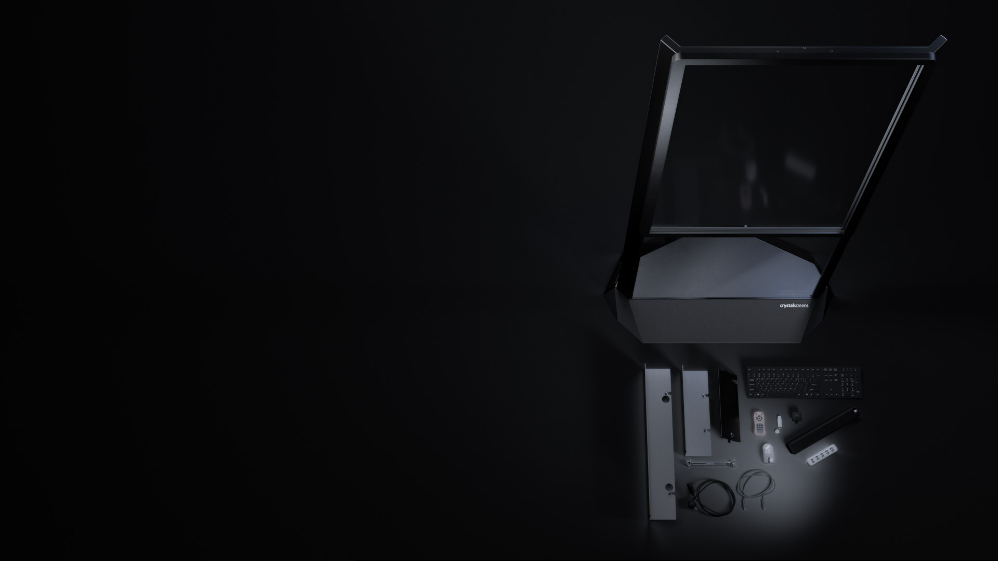
ADDITIONAL COMPONENTS SHIPPED WITH EVERY SYSTEM
Remote Control and Sensor
A remote control, used to access the OSD, is included with all systems. Refer to „Using the Remote Control“ on page 12 for details
on operation and function.
Rear panel Cover
The rear panel cover closes the stele foot and restricts access to the I/0 features when locked with its key. Never try to turn the key
with force! Instead: move the cover slightly until the key turns easily. Remove the key when the cover is locked to prevent accidental
break off of the key.
Cables
A 220VAC cable is included.
Transport Plates
Two transport plates with screws are included. Every system is shipped with the transport plates attached. The transport plates must
be re-installed before returning the system in its designated flight case. A combination spanner is included for mounting and demounting the plates. It is kept in the flight case compartment on the back of the flight case.
OPTIONAL ACCESSORIES
Camera
An external camera can be ordered separately. This is attached to the top of the system. Please let us know your camera requirements
before ordering.
Cables for external Player
An angled USB-B cable for IR touch connection and a flexible HDMI cable can be booked. These special cables are needed to enable
rear panel cover closing while having an external player connected to the system. Standard USB and HDMI cables are too big and
protrude too much from the rear panel so that a closing of the cover is prevented.
LAN Cable, UMTS Stick, USB Hub, Mouse & Keyboard
Can be ordered seperately.
Loudspeaker
The Teufel Bamster is „... a real power station that indulges the listener with rich basses as well as with gentle sounds“ *. Its design
perfectly integrates into our Stele look. Just connect it to headphone jack in the I/O rear panel and place it onto the Stele foot. For
more information visit: www.teufelaudio.com
ADDITIONAL COMPONENTS
© 2017 united.screens GmbH
Page 9
UNPACKING AND INSTALLING THE CRYSTAL SCREENS T-OLED
SAFE HANDLING
Flight Case
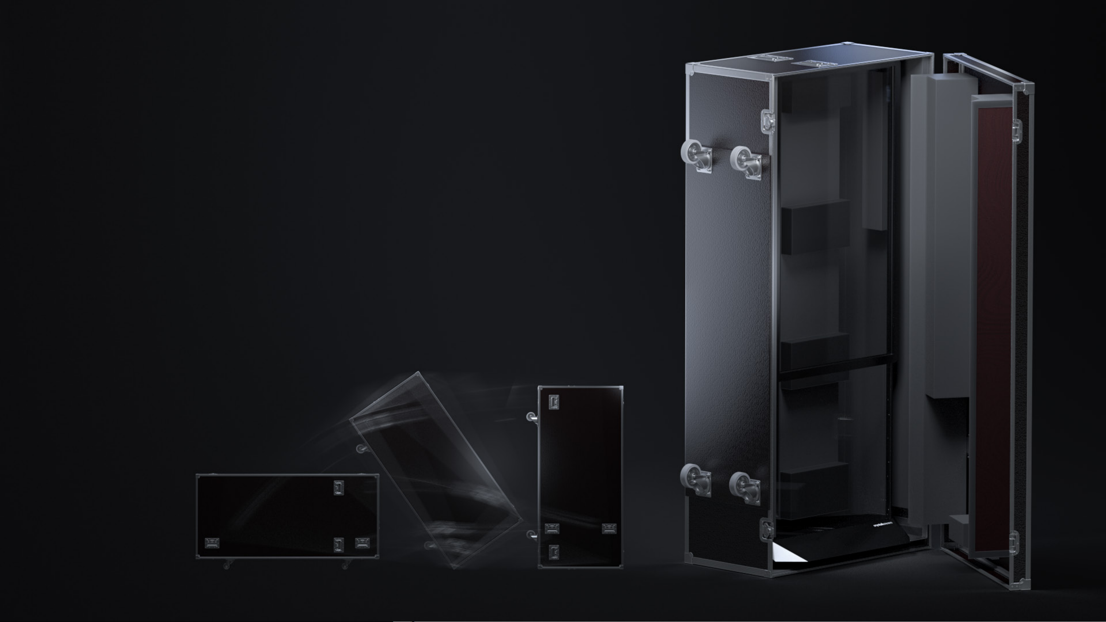
Before opening the CRYSTAL SCREENS Flight Case, it must be brought into an upright position. The castor brakes must be locked
and two persons are needed to set up the flight case. Pay attention to the UP arrows on the flight case, which need to point upwards
once the case stands in upright position.
Unpacking
Open all 4 butterfly closures. A butterfly catch is secured with a combination lock. The corresponding numerical code is located on
the warning sign on the side of the flightcase. Now pull the cover off the flightcase.
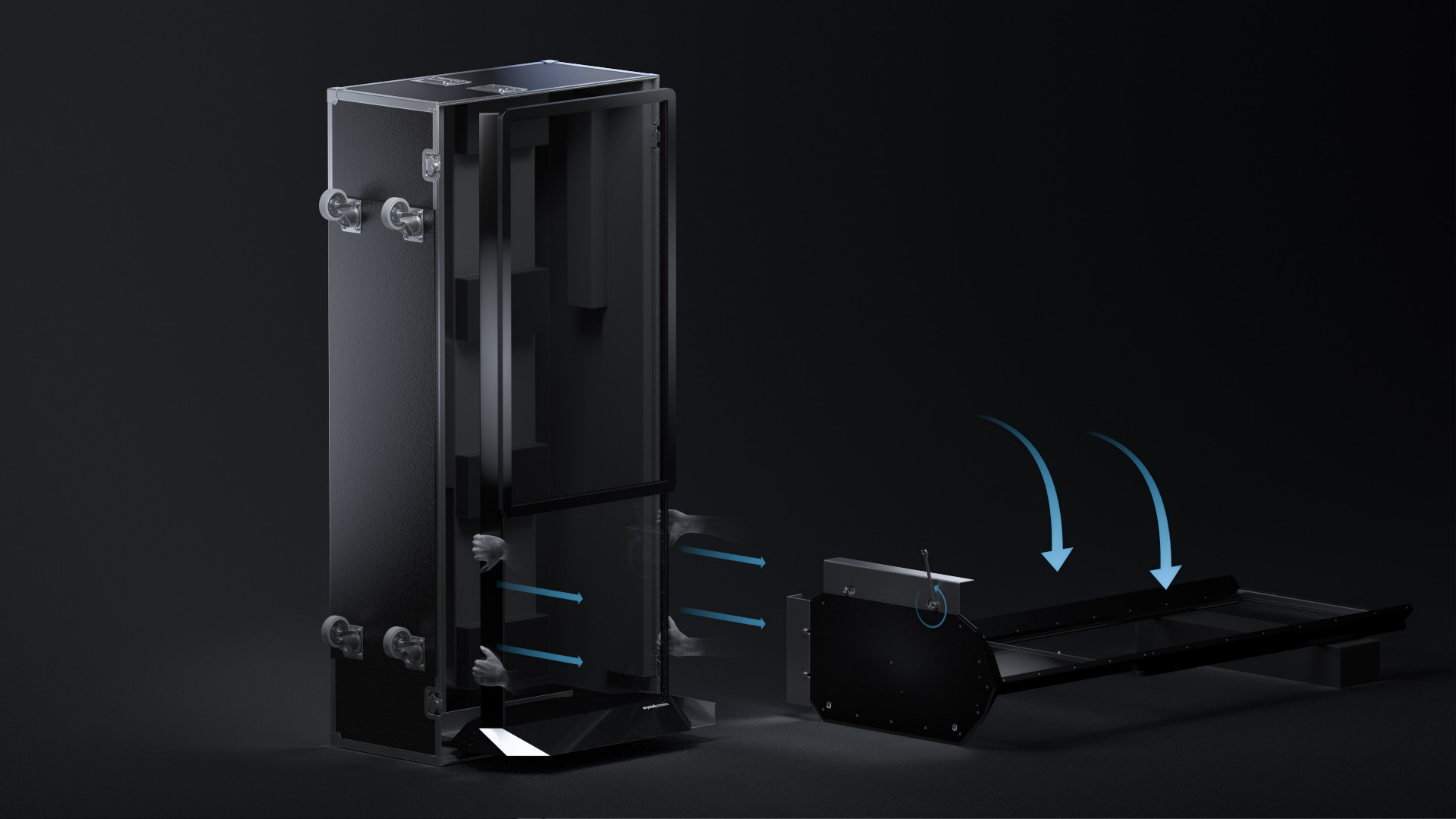
When removing the system from its flight case, use the indicated handhold locations shown in the picture below.
We recommend the stele be handled by at least two people. At no time should the IR frame be held where the weight of the stele is
borne by the IR frame. Proper handling is demonstrated in the picture below.
Be certain any surface where the system(s) will be placed can safely support the 165 lbs (75.0 kg) weight of the system. When using
a sack barrow to move the stele, the long transport plate must be installed to prevent damage from the angled stele foot. The stele
must only be moved with a sack barrow from its rear side. To prevent the TOLED panel to be put under strain by the upper part of
the sack barrow, use a hard foam or Styrofoam piece which is wider than the stele struts.
UNPACKING AND INSTALLATION
© 2017 united.screens GmbH
Page 10
UNPACKING AND INSTALLATION
© 2017 united.screens GmbH
Page 11
ENVIRONMENTAL CONSIDERATIONS
• The Crystal Screens is intended for indoor use only.
• Systems should only be installed in an environment where the temperature and humidity are kept within the proper use range.
See the Environmental Specifications on page 19.
• Crystal Screens displays are not designed to be sunlight readable.
• Do not locate the displays in direct sunlight or where the Display Glass will be exposed to ultraviolet (UV) light.
• The stele foot carrying the electronics should not be located near heat sources or in an environment where there is less than
20 mm of free space on all sides. Note that the Display Glass and the Display Chassis do not rise in temperature much above
ambient during operation.
• For best use of the display transparency, make certain there is adequate illumination in the space behind the screen so that
items of interest can be viewed optimally through the display. We recommend you experiment with the level and orientation
of the illumination.
INSTALLATION DISCLAIMER
Proper installation of the display is the responsibility of the end customer. Failure to follow the safety and installation instructions
in this manual or Content Developer‘s Guide, or any installation of the display in a manner not described in this manual or Content
Developer‘s Guide, may result in damage to the system or unsafe conditions, for which the renter will be made responsible for.
REQUIREMENTS FOR ALL INSTALLATIONS
Make sure the surface or structure where the display is to be mounted is capable of supporting the weight of the display or displays
to be used. Consult the „Specifications“ section on page 19 for weights and measures. If the display is to be attached to a surface or
structure, use the four M8 mounting points in the Stele foot as the primary attachment point. No fewer than two of mounting holes
should be used in any installation. Make sure the Display Glass maintains a neutral position and is not loaded in any way. The front
Display Glass surfaces should be mounted straight and plumb, i.e. perpendicular to the horizontal in all axes.
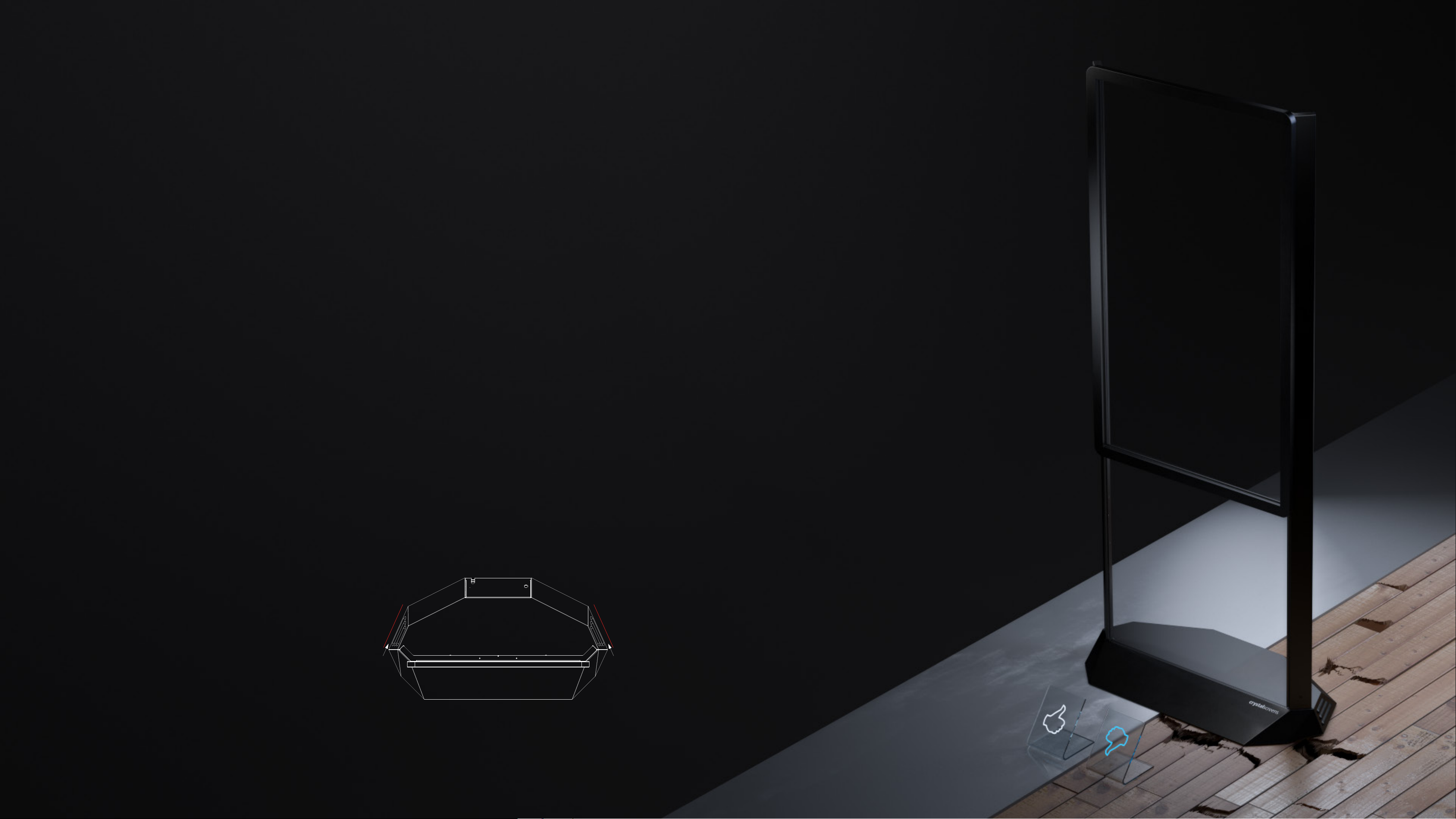
For mounting a Crystal Screens, the leveling feet must be removed. For this purpose, please lay the column carefully on the floor
by means of two persons so that the pedestal foot is vertical. Attention: please ensure that foam/foam parts are provided for the
upholstery of the upper part of the column/display chassis. The levelling feet can then be safely removed.
The ventilation openings in the Stele foot are a part of the thermal management system and should never be covered or have any
solid surface be located closer than what is defined in the figure below.
UNPACKING AND INSTALLATION
20mm20mm
© 2017 united.screens GmbH
Page 12
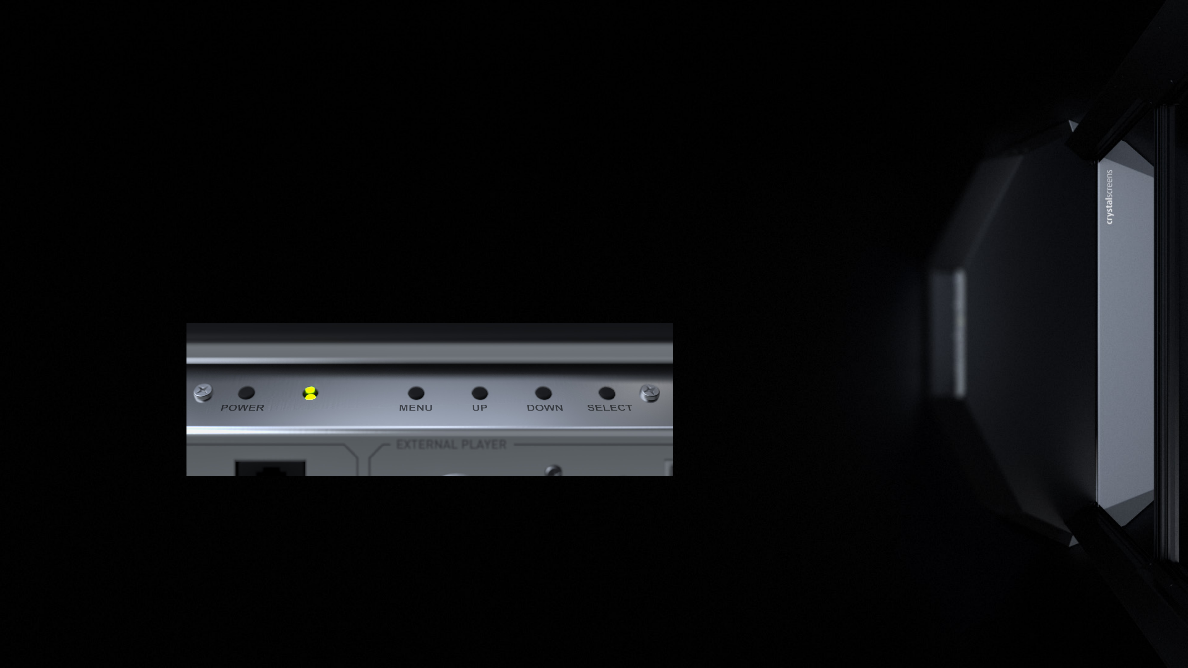
OSD KEYPAD
OSD KEYPAD BUTTONS
POWER MENU UP DOWN SELECT
Power ON / Power OFF Main Menu Menu Up Menu Down Select / Enter
MENU DOWN
Back / Exit Source selection (use select to confirm)
OPERATING THE DISPLAY
© 2017 united.screens GmbH
Page 13
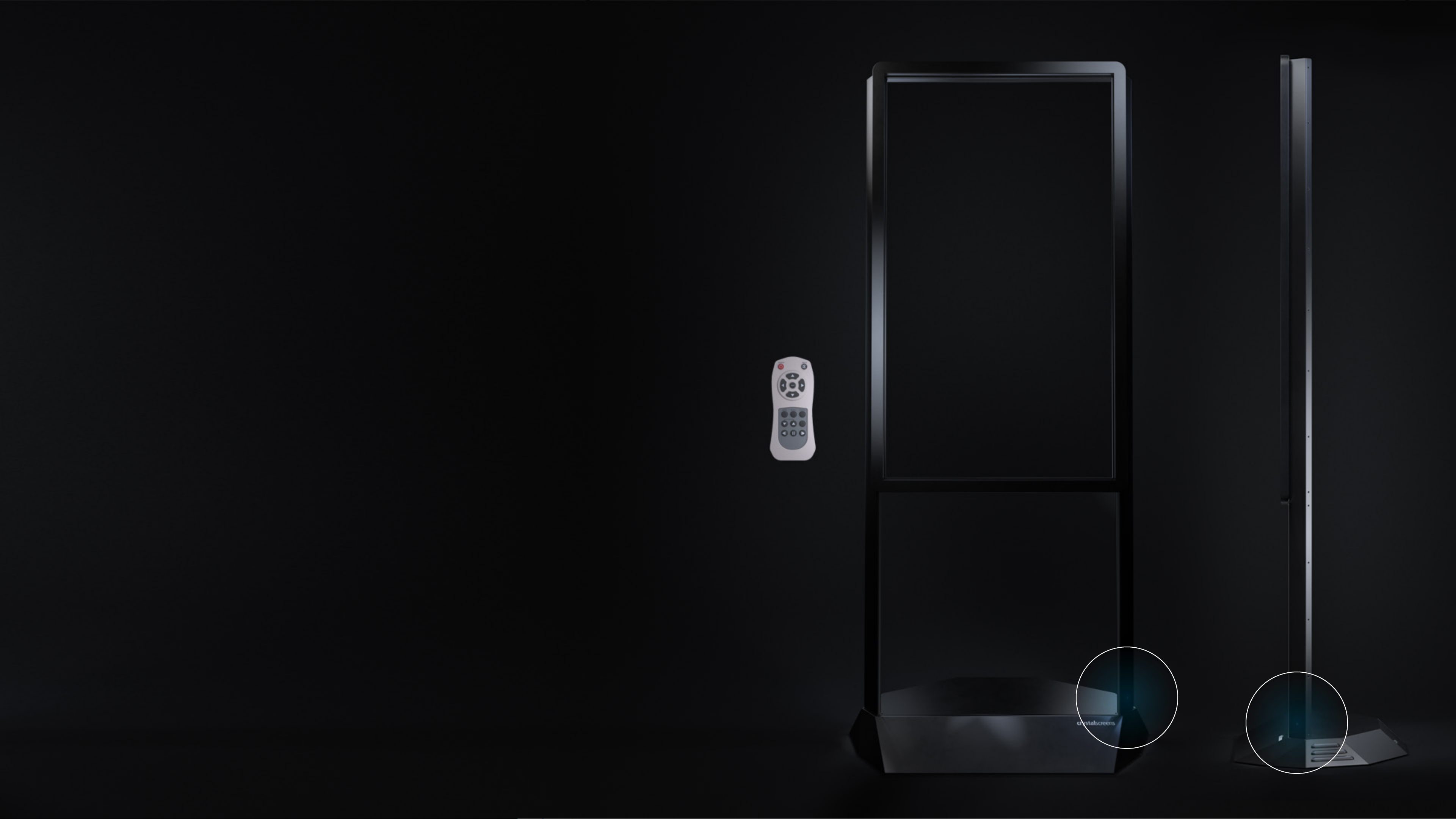
USING THE REMOTE CONTROL
The Remote Control included with every Crystal Screens model is shown on the right. An IR sensor is
located in the lower part of the right Stele strut. The shaded circles in the figures on the right indicate the
approximate range of coverage of that sensor.
OPERATING THE DISPLAY
© 2017 united.screens GmbH
Page 14
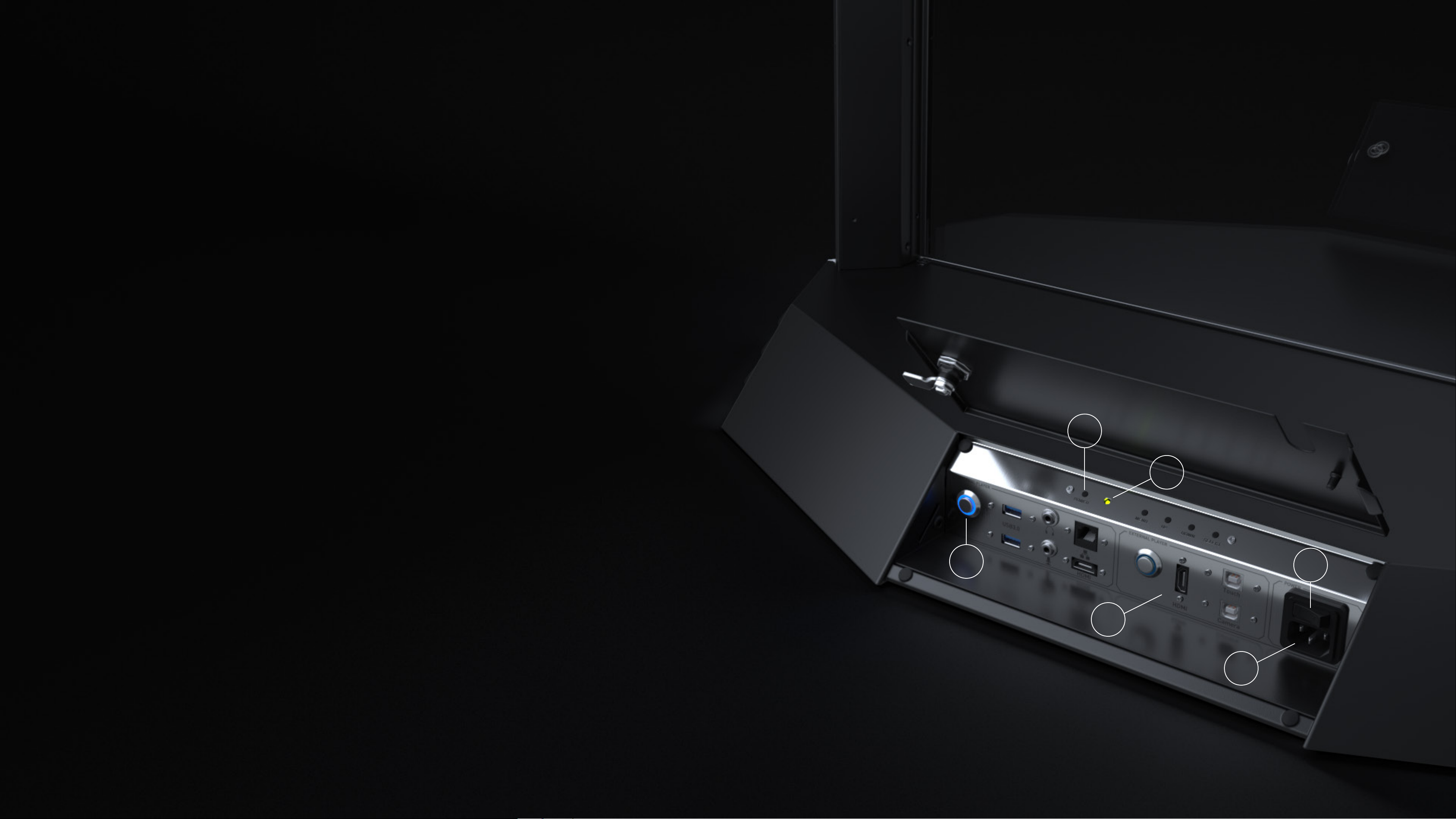
TURNING THE SYSTEM ON
1. Insert the power cord into the Stele and into the power outlet.
2. Ensure the AC switch is set to “I”
3. Press the Power button on the remote or on the keypad.
4. Press the Power button of the internal player (for at least 1 second).
Note: If no digital input is connected, the display will wait for a few seconds and then switch the display
into Power Saving Mode. The LED indicator turns from green to red. This will occur until a digital input is
established.
TURNING THE SYSTEM OFF
With the power on, press the POWER button on the remote or the power button on the keypad to put the
Crystal Screens in a standby mode.
Note: This does not switch off the integrated PC! To switch off the integrated PC, use the ON/OFF icon in
the Windows Start menu and shut down the PC. The integrated PC is switched off when the blue LED ring
around the POWER button in the Internal Player area is off. (4)
To fully turn off the system, turn the power switch to „0“ or unplug the power cord from the wall outlet.
Note: Do not switch off the system using the power switch if the integrated PC is still running.
CONNECTING AN EXTERNAL PC
Press the Power Button of the external Player (5) and connect your external computer/playback device via
the HDMI connector. Connect the touch with an USB-B to USB-A cable. Turn on the OLED via the keypad
or the remote and then start your external computer/playback device.
Note: If the OLED does not automatically recognize the external input, use the remote SOURCE button or
the keypad DOWN button (use SELECT to confirm) to switch to HDMI input.
OSD KEYPAD LED INDICATOR
The LED indicator light (6) is visible next to the power button of the OSD keypad
LED STATUS OPERATING STATUS
Led Green Normal
Led Red Power Saving
Led Off Power Off
FRONT VS REAR VIEWING
Because each pixel is emitting its own light, the display can be viewed from the back as well as the front.
However, the light emitted toward the rear is much less than that on the front and any image viewed
from behind will be reversed.
OPERATING THE DISPLAY
4
3
6
2
5
GLASS TREATMENT
The front surface of the Display is made of toughened Glass that is installed in front of the OLED panel
and covered with an anti-reflective coating. The toughened Glass provides scratch resistance on the front
of the display only. The back side of the display is susceptible to damage from sharp and/or hard objects
and should be protected accordingly.
1
© 2017 united.screens GmbH
Page 15
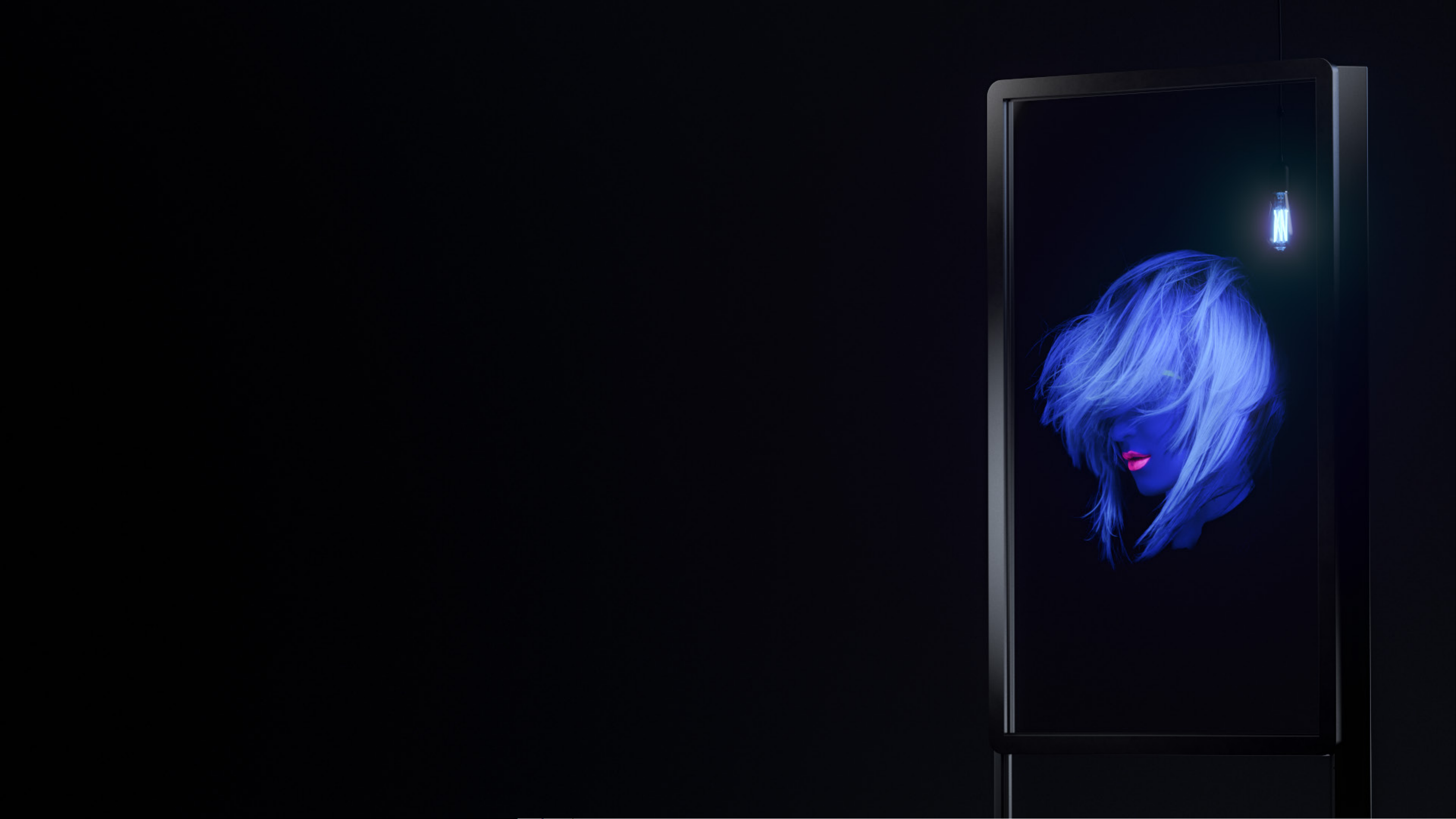
USING THE TOUCH SCREEN
You can use the touch screen to control your Windows (Mac, or Linux via external PC) operating system.
The Crystal Screens is HID compliant, delivering up to 10 points of touch on both Windows and Linux
without a driver. Single touch only is supported for Mac operating systems. There is no driver required to
enable Mac support.
DEVELOPING CONTENT
We strongly recommend you make use of the Crystal Screens Transparent Display Content Developer‘s
Guide at www.united-screens.tv/downloads
Use of this guide will both enhance the viewing experience of your Crystal Screens users and maximize the
life of the display.
Note: SBD – Stress boundary diffusion
The OLED has a „burn-in protection“ against static contents, as the organic components in the display
would otherwise be subject to a faster aging process if a region were to be permanently illuminated. This
burn-in protection moves the image clockwise by one pixel at regular intervals to prevent this. However,
since this shift occurs only for the image and not for the touch overlay, there is sometimes a shift of up
to 13mm between the touch and the image. Therefore, the touch buttons/surfaces of Custom Made
Apps should be about 4cm in diameter (the larger touch surface can also be invisible, i. e. simply larger
than the visible button). This ensures that touch surfaces are always hit correctly. Furthermore, a distance
of approx. 2cm to the outer edge of the content area should be maintained to prevent the SBD from
„cutting off“ the content. For Windows10 operating systems, a higher value for the size of text, apps and
other elements can be set in the display settings to increase the size of touch surfaces such as buttons, etc.
OPERATING THE DISPLAY
© 2017 united.screens GmbH
Page 16
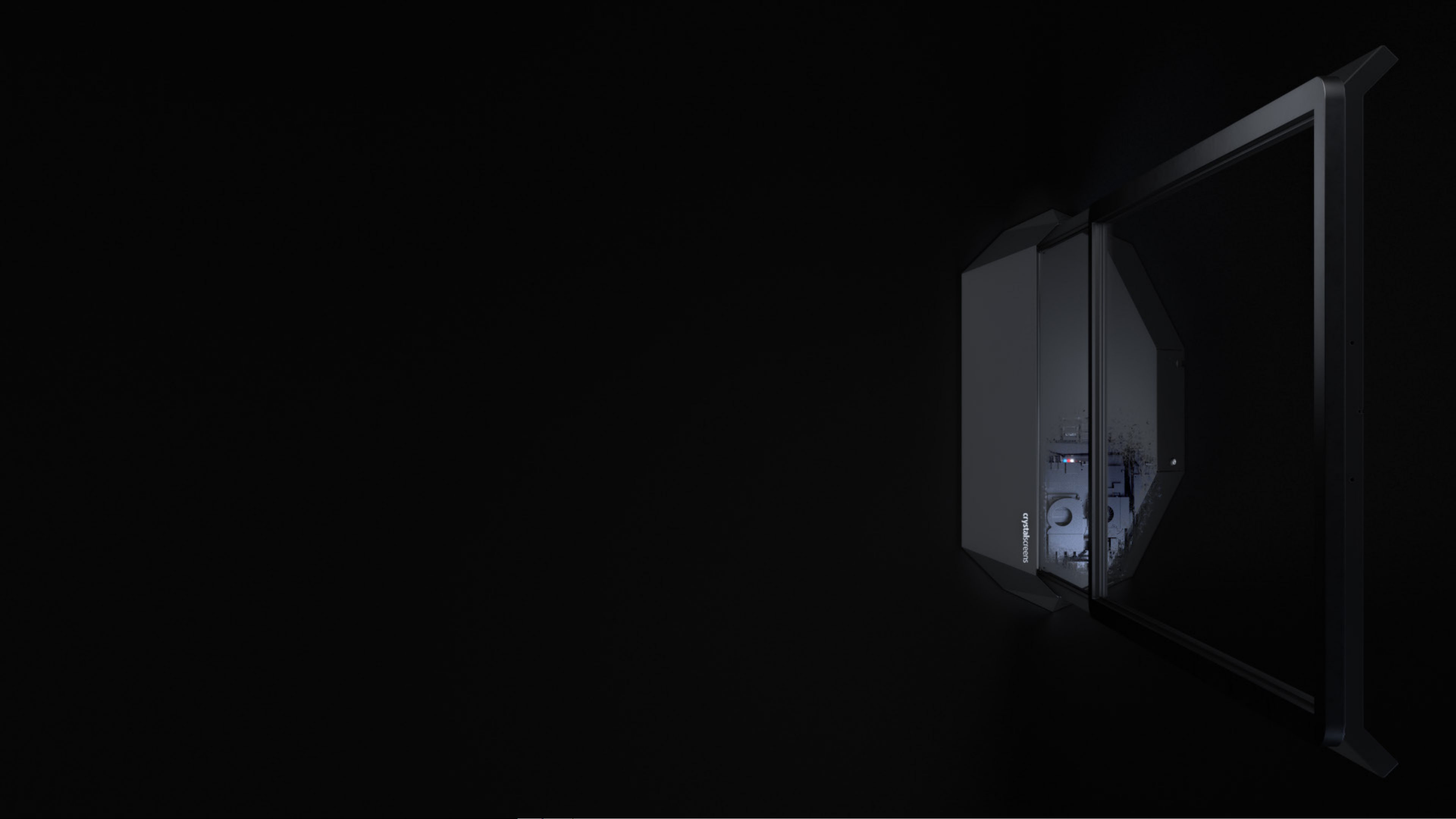
The integrated PC is powered by an Intel Skylake Core i5-6400T processor (quad-core 2.2 GHz, up to 2.8
GHz) and a NVIDIA GeForce® GTX 960, enabling a superior performance for FHD video playback and
demanding interactive applications.
The latest version of Windows 10 Home is pre-installed as well as Adobe Acrobat Reader DC, the Mozilla
Firefox Browser and a Power Point Viewer.
For further information on the specs of the integrated PC please see the full specifications on page 19.
FEATURES
• Intel Hyperthreading technology
• Intel Clear Video technology
• 4K Support
• Microsoft DirectX 12 compatible, feature level 12_1
• NVIDIA® Maxwell™ Architecture
• 802.11ac WiFi & Bluetooth 4.0
INTEGRATED PLAYBACK PC
© 2017 united.screens GmbH
Page 17
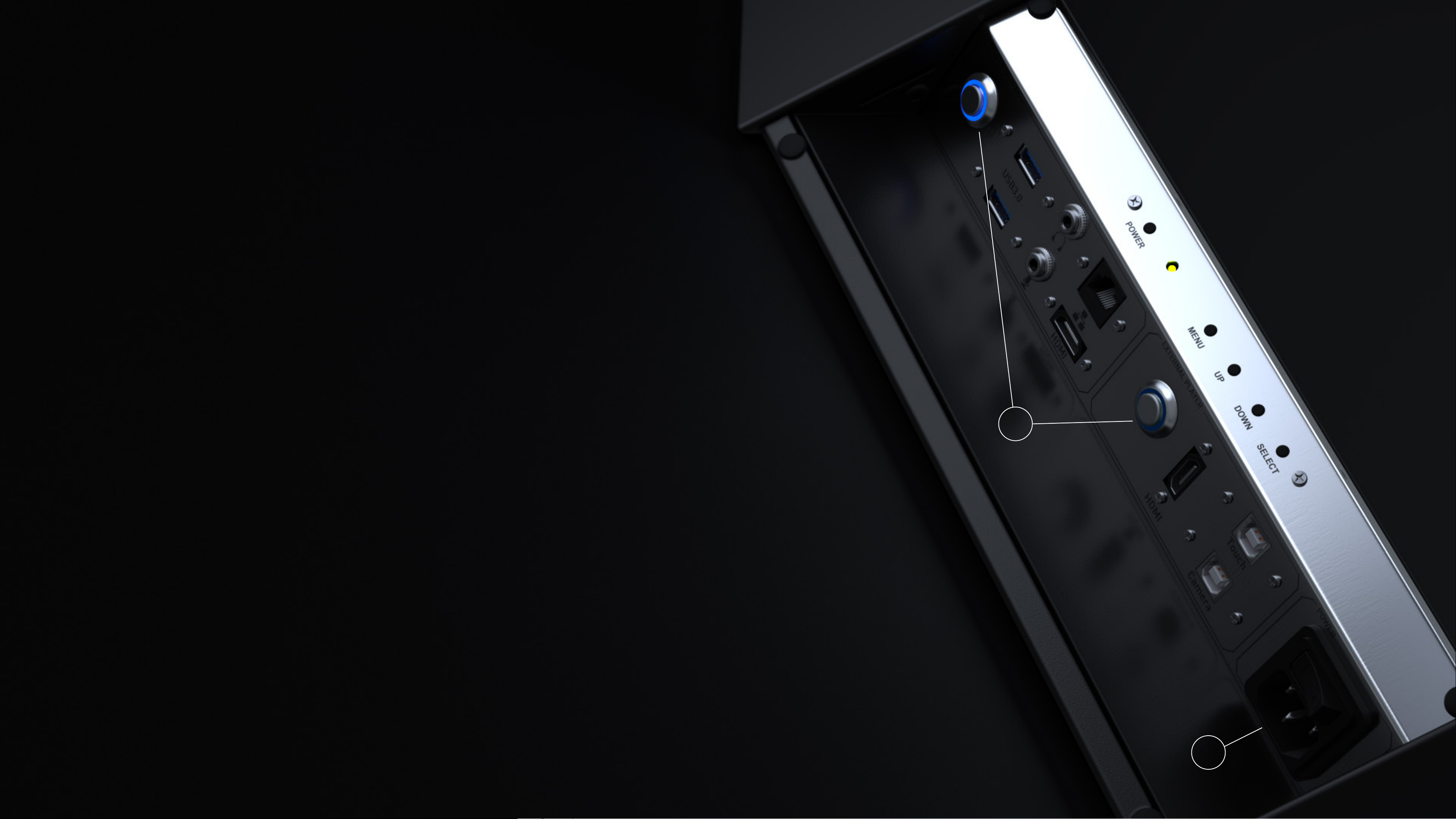
When the power switch is toggled from the „o“ switch position (power off) to the „I“ switch position
(power on), you should see green LED illuminate in the keypad section on the rear panel. If the LED
indicator is red, please press the POWER button on the key pad. After less than 20 seconds you should
see an OSD info box stating that no input is detected if the internal PC is off and no external PC/player is
connected and running. If the internal PC is running or an external PC/player is connected and enabled,
the image from either source will be visible after couple of seconds. A Sources Status window from the
OSD will also be visible for a few seconds.
POSSIBLE PROBLEM: THE POWER SWITCH IS TOGGLED AND NOTHING HAPPENS.
Items to check: ( 1 )
Make sure that the power cord is securely connected at both ends and that the power supply is available.
Check the LED display in the OSD control panel. When it lights red, press the POWER button on the OSD
panel.
POSSIBLE PROBLEM: THE MONITOR POWERS ON AND SHOWS THE MISSING INPUT DIALOG SCREEN
BUT AFTERWARDS REMAINS EMPTY EVEN THOUGH THE INTERNAL OR EXTERNAL PLAYER ARE
RUNNING.
2
Items to check: ( 2 )
Check if the internal player is turned on. When the player is switched on, the blue LED ring lights up. If
necessary, a control display can be connected to the HDMI port in the Internal Player section to determine
if the internal player is running.
Check via OSD control panel or remote control which SOURCE input is selected on the display. DVI must
be selected for the Internal Player and HDMI for the External Player.
If these troubleshooting instructions do not resolve the problem, please contact United Screens’ Technical
Support team to determine the next steps.
TROUBLESHOOTING
Hotline during opening hours: +4940 23 51 45-0
Opening hours: Mo-Fr 9am – 6pm
1
© 2017 united.screens GmbH
Page 18
CLEANING THE CRYSTAL SCREENS T-OLED
Both after installation and throughout the life of the display, appropriate cleaning will be necessary.
METAL SURFACES
These can be wiped with an absorbent towel. Do not allow any liquid to get into the foot with the
electronics!
DISPLAY FRONT AND IR FRAME
Use a soft, lint-free cloth or paper. Microfibre cloths are best suited.
Use a high-quality glass cleaner suitable for LCD screens. A Premium Isopropanol (IPA) cleaner can also be
used alone or as a supplement to a glass cleaner. Use IPA separately from the glass cleaner, i. e. do not mix
it. Ideally, you should use different cloths for each liquid.
Note: IPA is flammable. Do not use the cleaner near open flames or other sources of ignition.
Glass cleaners or IPA must NOT get into the electronics base or into the area between display glass and
display housing/IR frame.
Apply cleaning fluid, glass cleaner or IPA sparingly to a cloth (not directly to the glass surface) and start on
one side of the screen. Wipe the screen evenly under circular movements. If you do not get a streak-free
surface, increase the amount of cleaning agent on the cloth and change the cloths more often.
CLEANING THE BACKSIDE OF THE DISPLAY GLASS
Use the same materials as described above. Liquids must not get into the area between the back of the
MAINTENANCE
display and the display chassis. Be even more careful. The back of the display has no protective glass.
Make sure that you use a clean cloth which is free of hard residues (crumbs, chips, etc.).
© 2017 united.screens GmbH
Page 19
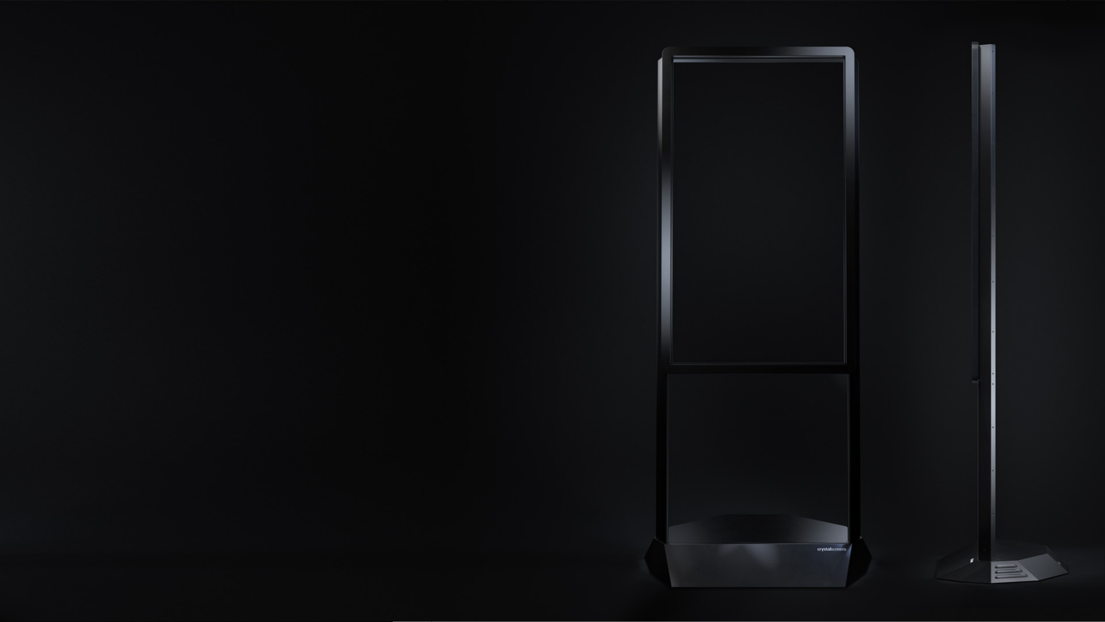
Specifications Crystal Screens T-OLED
AMOLED Panel
Resolution 1080 x 1920
Aspect Ratio 9 x 16
Screen Size 55“
Pixel Pitch 0.64mm
Viewing Angle 180°
Color Gamut 100% NTSC
# of Display Colors 1.07 Billion (10 bits)
Connectivity
Inputs HDMI 1.4 (external Player)
RJ45 -LAN (internal Player)
2 x USB 3.0 (internal Player)
Outputs HDMI 2.0 (internal Player)
Touch (external Player)
Camera (optional - external Player)
Control Elements Remote Control, OSD-Keypad
Mechanical
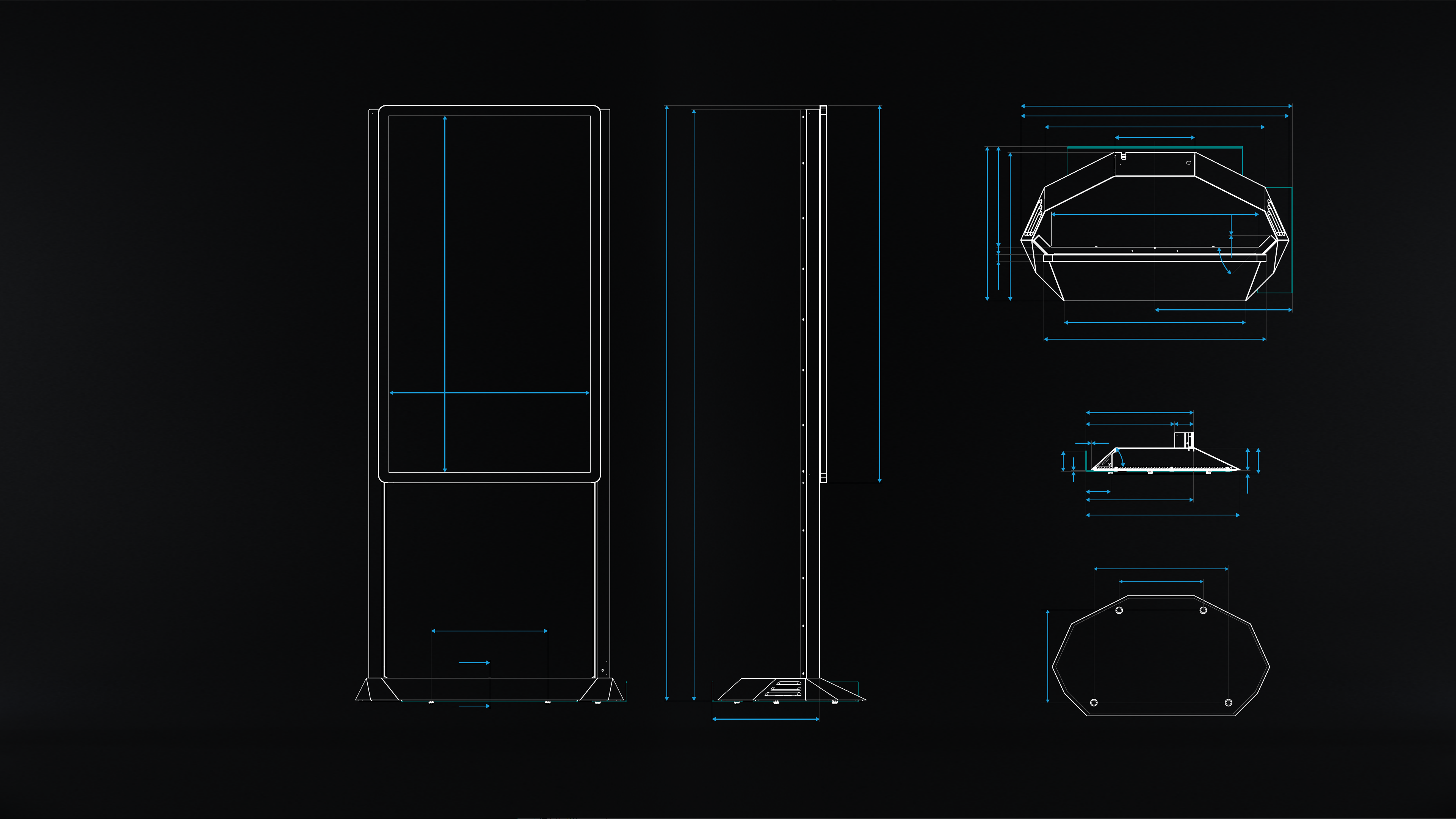
Aktive Screen 678.4 x 1208 mm
System Dimensions (cm)
Total 91.6 x 203.5 x 50.7 cm
Foot 91.6 x 77.5 x 50.7 cm
Touch Display Chassis 76.0 x 129.0 x 23.6 cm
System Weight (Kg) 75
Mounting Yes, 4 x M8
Usage
Recommended Usage ≤ 12 Std/Day, moving image, 75 nits avarage luminance
Luminous Life* 30.000 hours
Power/Electrical
Power consumption, Max 380W
Power consumption, Typ. (Video) 190 - 220W
Standby Power consumption < 0.5W
Input Voltage 100 - 250V / 50-60Hz
Front Glass
Glass Type toughened safety glass
SPECIFICATIONS
Touch
Touch Technology IR
Supporting OS Windows 7, 8, 10, Mac OSX und Linux
Detectable Touch Points 10
Min detectable Object 1.5mm
Touch Sample Rate up to 250 fps
Environmental
Storage temperature -20 to 60
Operating temperature 0 to 35
Integrated PC
Operating System Windows 10
CPU/Chipset Intel Skylake Core i5-6400T (quad-core, 2.2 GHz, up to 2.8 GHz)
System Memory 8 GB DDR3L-1600
Grafics NVIDIA GeForce® GTX 960 - 1280 CUDA Cores / 3GB GDDR5 memory / 192-bit
USB Ports 2 x USB 3.0
Storage Samsung SSD 750 Evo 2,5 120GB SATA III (6 Gb/s)
LAN/RJ45 10/100/1000 Mbps operation - supports IEEE 802.3
WiFi/Bluetooth 802.11ac WiFi & Bluetooth 4.0
Audio Stereo analog Audio output and Microphone input - Loss-less Bitstream via HDMI
*Time to 50% of the output brightness, at 25° C, moving image and an average luminance of 75 nits.
© 2017 united.screens GmbH
Page 20
684,39
2021
Schnitt A-A
19,9
368,2
302,9
65,3
368
527
77,510,5
85
398
70
3
42,1°
88
2035
368
A
A
2021
2035
1290
368
Schnitt A-A
368,2
302,9
65,3
368
527
77,510,5
42,1°
88
368
527
343,5
507,1
928,1
916,3
752,3
274
710
40,6
45°
1218
684,39
2035
2021
1290
23,6
70
470
620,8
760
Schnitt A-A
368,2
302,9
19,9
42,1°
3
85
368
65,3
77,510,5
88
527
LINE DRAWINGS
M8 M8
398
A
A
384
M8 M8
368
560
350
© 2017 united.screens GmbH
Page 21
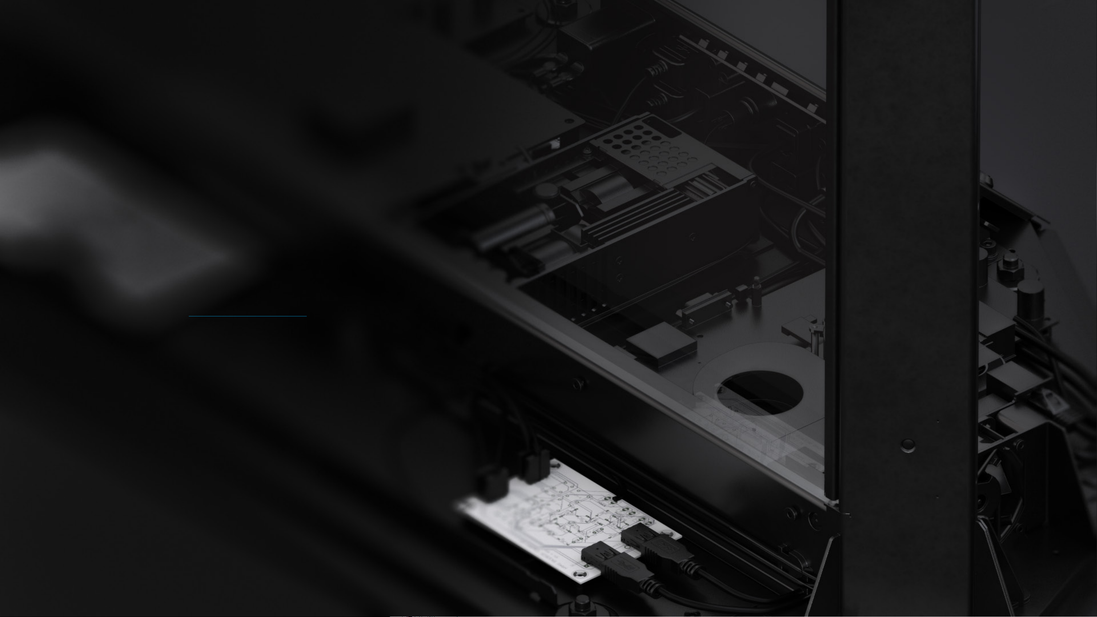
ACCESSING UNITED SCREENS TECHNICAL SUPPORT
Visit www.united-screens.tv/downloads for the following documents and resources:
• This user manual
• United Screens Content Developer’s Guide
• Support Hotline and email
TECHNICAL SUPPORT
© 2017 united.screens GmbH
Page 22
Manufacturer Name: United Screens GmbH
Manufacturer Address: Langenhorner Chaussee 155, 22415 Hamburg, Germany
IMPRINT
© 2017 united.screens GmbH
Page 23
Copyright © 2017 United Screens GmbH. All Rights reserved.
The content of this publication may not be reproduced without the consent of United Screens GmbH.
Trademarks
Windows ™ is a trademark of Microsoft Corp.
All other names are trademarks or registered trademarks of their respective companies.
Disclaimer
The information contained in this document is subject to change without notice. United Screens GmbH
does not assume any guarantee for this material. Although precautions have been taken in preparing
this manual, the Company is not liable for any errors or omissions contained herein, or for incidental or
consequential damages in connection with the provision, performance or use of this material.
RoHS Declaration of Conformity
The Crystal Screens T-OLED is fully RoHS compliant.
Copyright © 2017
© 2017 united.screens GmbH
 Loading...